Predator PO5-640 User manual

Table of Contents -
1
Predator
PO5-640
User’s Manual

-
2
© 2021. All Rights Reserved.
Desktop Computer Covers:
Tower models
This revision: Dec. 2021 V1.01
Important
This manual contains proprietary information that is
protected by copyright laws. The information contained in
this manual is subject to change without notice. Images
provided herein are for reference only and may contain
information or features that do not apply to your computer.
Acer Group shall not be liable for technical or editorial errors
or omissions contained in this manual.
The terms HDMI and HDMI High-Definition Multimedia
Interface, and the HDMI Logo are trademarks or
registered trademarks of HDMI Licensing Administrator,
Inc. in the United States and other countries.

Table of Contents -
3
Table of Contents
1. UPGRADING YOUR COMPUTER........5
Installation precautions
..................5
ESD precautions
.................................5
Required tools
......................................5
Pre-installation instructions
.....6
Post-installation instructions
..6
System Upgrade
...................................7
Removing the Left side system
cover
.............................................................7
Installing the Left side system
cover
.............................................................7
Removing the Right side
system cover
.........................................9
Installing the Right side
system cover
.......................................10
System Layout
....................................11
Hard drives
.............................................12
Removing the 3.5-inch hard
drives
.........................................................12
Installing the 3.5-inch hard
drives
.........................................................13
Memory
....................................................14
Memory configuration
guidelines
...............................................14
Removing a memory module
..16
Installing a memory module
...18
Graphics board
....................................19
Removing the Graphics board
19
Installing the Graphics board
22
M.2 SSD module
.................................24
Removing the M.2 SSD module
........................................................................24
Installing the M.2 SSD module
........................................................................25
Dust filter
...............................................26
Removing the Dust filter
............26
Removing the Top Cover
............27
Removing the Front Bezel
........28
2. PREDATORSENSE............................... 30
PredatorSense features
................ 30
LED on Motherboard
....................32
Motherboard LED Settings
......32

-Upgrading your Computer
4
Upgrading your Computer
In this section, you will find:
•
Instructions on how to replace a hardware
component

Upgrading your Computer -
5
1. UPGRADING YOUR COMPUTER
Installation precautions
Before you install any computer component, we recommend
that you read the following sections. These sections contain
important ESD precautions along with pre-installation and
post-installation instructions.
ESD precautions
Electrostatic discharge (ESD) can damage your processor,
disk drives, expansion boards, and other components.
Always observe the following precautions before you install
a computer component:
1.
Do not remove a component from its protective
packaging until you are ready to install it.
2.
Wear a wrist grounding strap and attach it to a metal
part of the computer before handling components. If a
wrist strap is not available, maintain contact with the
computer throughout any procedure requiring ESD
protection.
Required tools
In performing the component replacement process, you will
need the following tools:
•
Philips screwdriver
•
Hex screwdriver
•
Flat screwdriver
•
Scissors
Note
The screws for the different components vary in size. During
the disassembly process, group the screws with their
corresponding components to avoid mismatches when
putting back the components.
-Upgrading your Computer
6
Pre-installation instructions
Always observe the following before you install any
component:
1.
Make sure that the ODD and card reader slot is empty.
2.
Turn off the power to the computer and all
peripherals.
3.
Unplug the power cord from the computer.
4.
Unplug the network cable and all connected peripheral
devices from the computer.
5.
Place the computer on a flat, steady surface.
6.
Open your computer according to the instructions on
removing the left side system cover on page 7 and
removing the right side system cover on page 9.
7.
See the following sections for specific instructions on
the component you wish to install.
Post-installation instructions
Observe the following after installing a computer component:
1.
See to it that the components are installed according
to the step-by- step instructions in their respective
sections.
2.
Replace any expansion boards or peripherals that you
removed earlier.
3.
Replace the system covers. See Installing the left side
system cover on page 8 and installing the right side
system cover on page 10.
4.
Connect the necessary cables.
5.
Turn on your computer.
Warning
Not turning off the computer properly before you start
installing the components may cause serious damage. Do not
attempt the procedures described in the following sections
unless you are a qualified service technician.
WARNING: Hot surface. Do not touch.
Upgrading your Computer -
7
System Upgrade
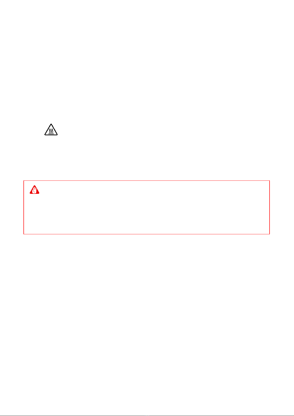
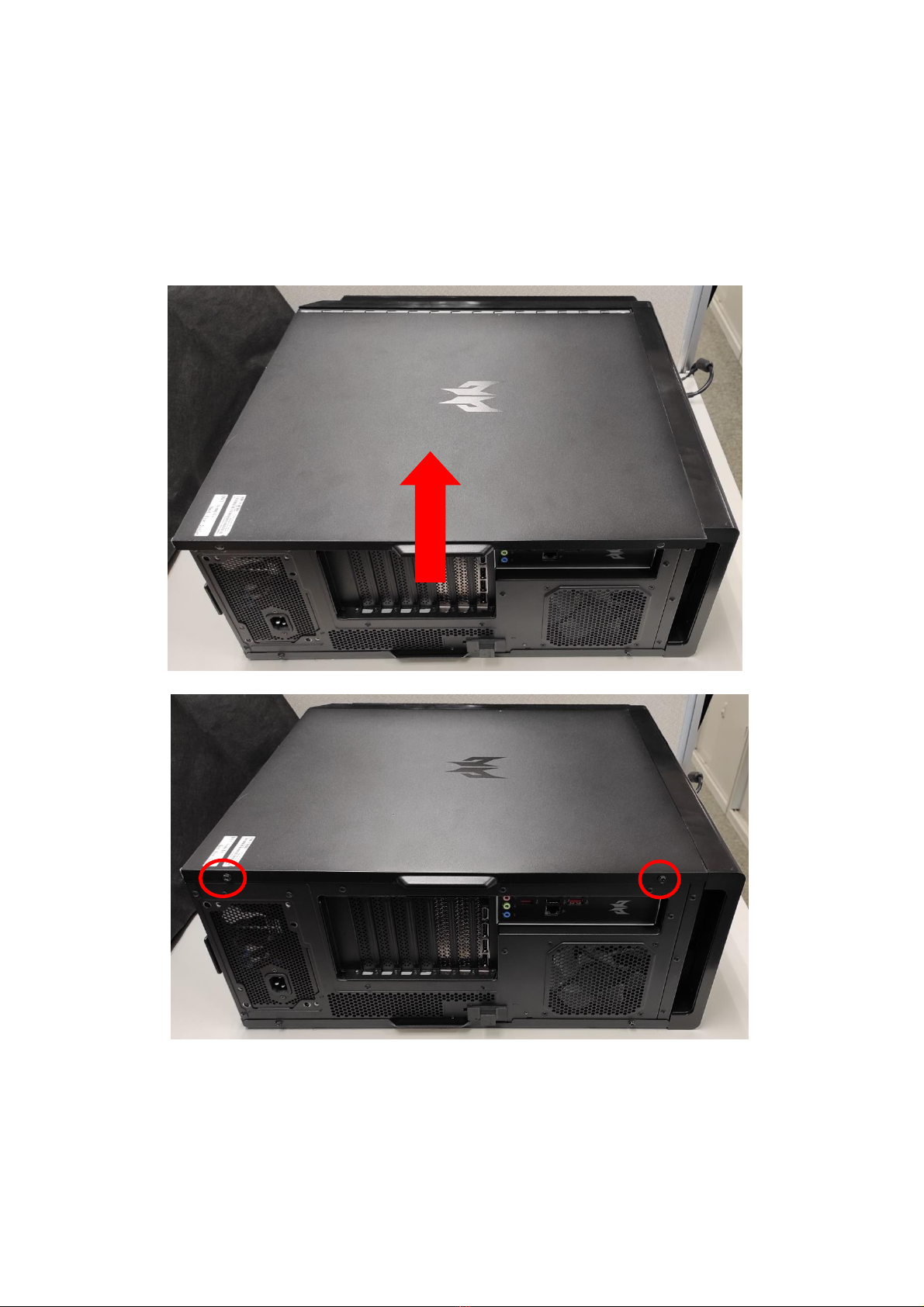
Removing the Left side system cover
1.
Before you proceed, make sure that you have turned
off your computer and all peripherals connected to it.
Read the Pre- installation instructions on page 6.
2.
Remove the two screws that secure the system cover
to the computer.
3.
Slide the cover toward the back of the computer and
pull away from the top of the computer.
4.
Set the cover aside for re-installation later.
Note
When disassembling, the machine must lie flat and not upright
-Upgrading your Computer
8
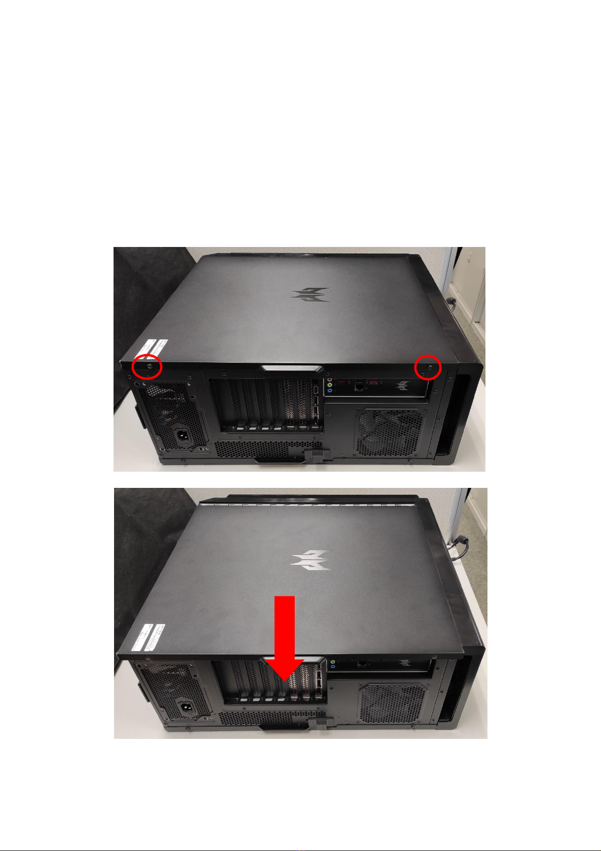
Installing the Left side system cover
1.
Align the cover hook to the sides of the computer and
slide the cover toward the front of the computer.
2.
Secure the cover with two screws.
3.
Observe the Post-installation instructions on page 6.
Upgrading your Computer -
9
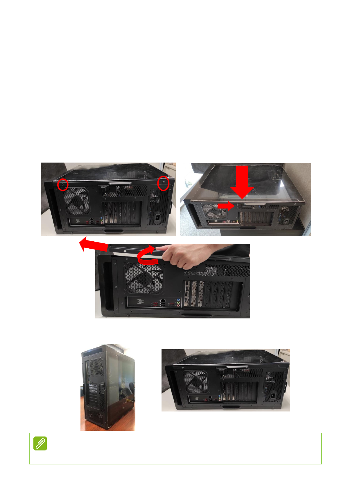
Removing the Right side system cover
1.
Before you proceed, make sure that you have turned
off your computer and all peripherals connected to it.
Read the Pre- installation instructions on page 6.
2.
Remove the two screws that secure the system cover
to the computer.
3.
Slide the cover toward the back of the computer and
pull away from the side of the computer.
4.
Set the cover aside for re-installation later.
-Upgrading your Computer
10
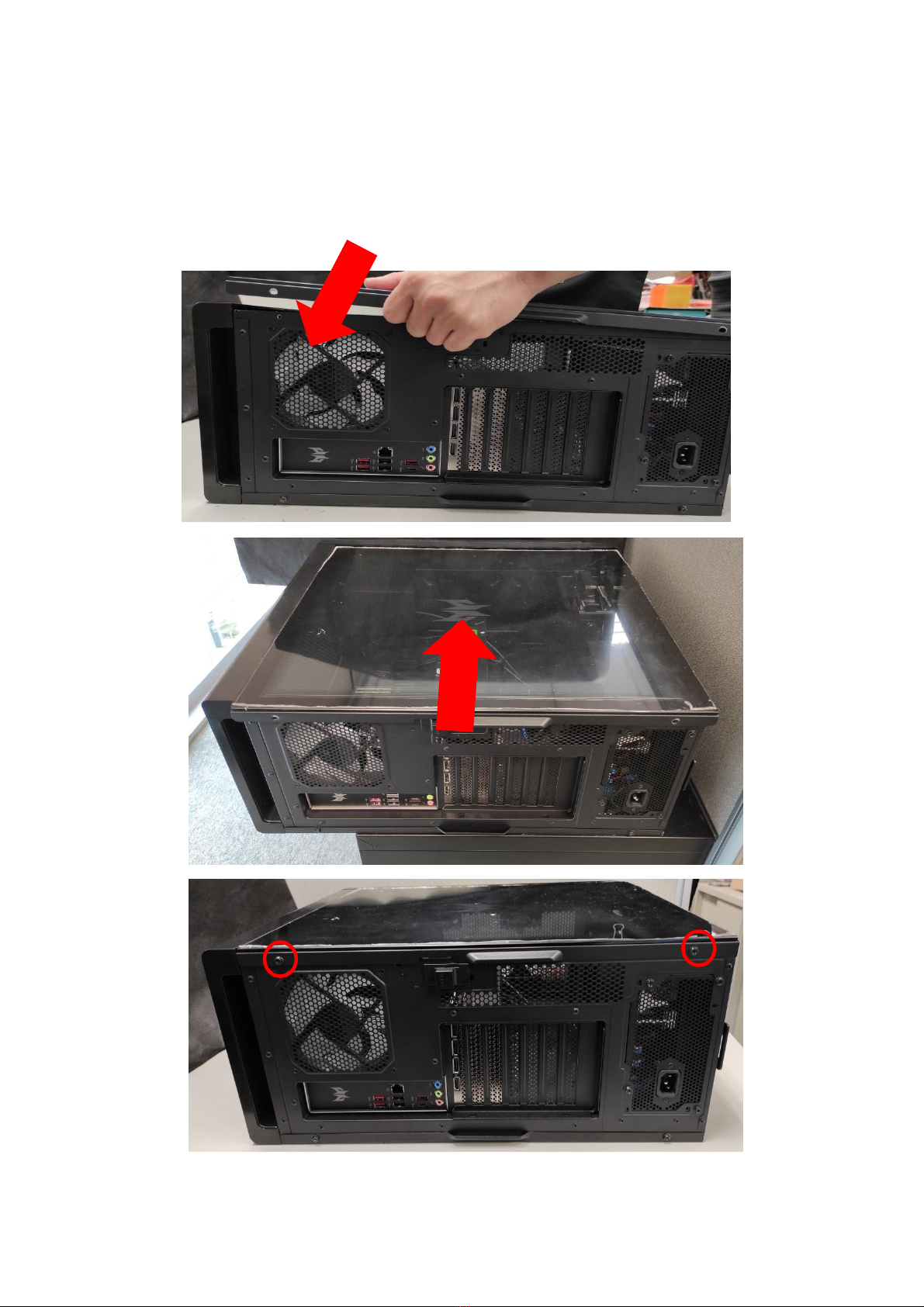
Installing the Right side system cover
1.
Align the cover to the sides of the computer and slide
the cover toward the front of the computer.
2.
Secure the cover with two screws.
3.
Observe the Post-installation instructions on page 6
Upgrading your Computer -
11
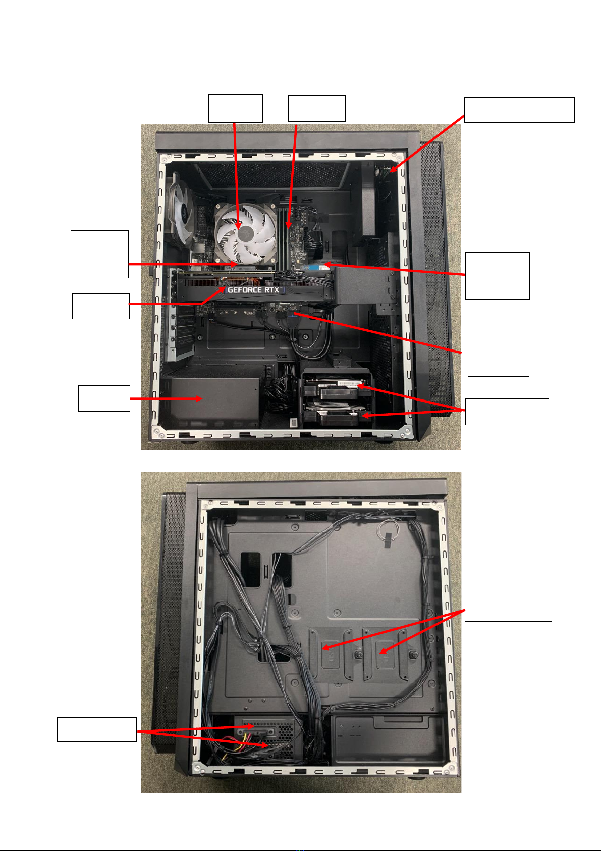
System Layout
3.5HDD
2.5”HDD
SSD
M2_2
VGA
SSD
M2_3
Wifi
M2_1
RAM
CPU
PSU
3.5HDD
FIO Module
-Upgrading your Computer
12
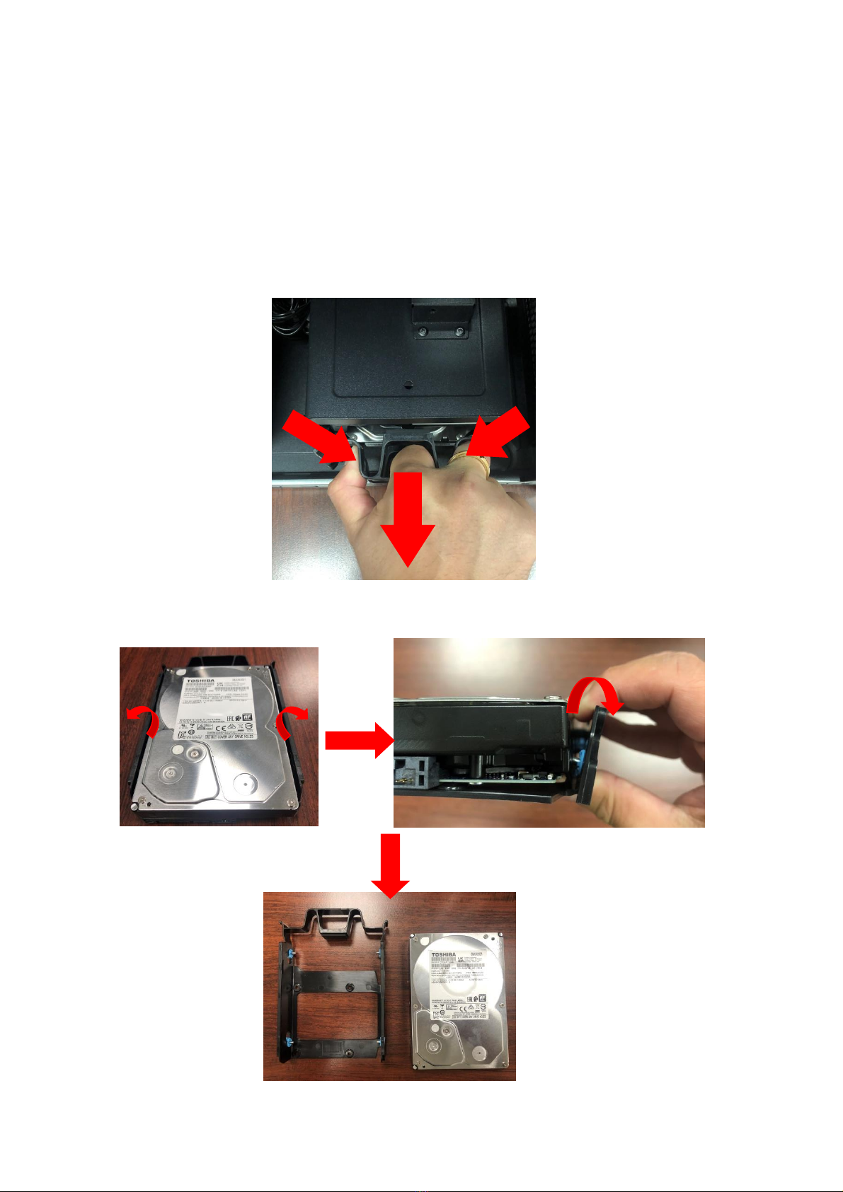
Hard drives
The computer supports installation of two 3.5-inch SATA
hard drives in the internal HDD cage.
Removing the 3.5-inch hard drives
1.
Perform Pre-installation instructions on page 6.
2.
Pull black rack out from HDD cage and take it off.
3.
Remove the hard drives from the rack.

Upgrading your Computer -
13
Installing the 3.5-inch hard drives
1.
Remove the new hard drive from their packaging.
2.
Insert the new hard drive into the black rack.
3.
Insert black rack into HDD cage.
4.
Observe the Post-installation instructions on page 6

-Upgrading your Computer
14
Memory
The computer has four DDR5 U-DIMM slots that support
up to 64 GB maximum system memory.
Memory configuration guidelines
•
To ensure data integrity, use only Acer-approved DDR5
memory modules.
•
Memory modules must be installed starting with DIMM1
slot.
•
Always handle memory modules by its edges.
•
When installing memory modules, populate the DIMM
slots according to the table below.
D1
D3
D2
D4
DIMM 1
DIMM 2
DIMM 3
DIMM 4

Upgrading your Computer -
15
Rule
DIMM1
DIMM3
DIMM2
DIMM4
Memory A>B
(Different
capacity value)
A
/
/
/
A
/
A
/
A
/
B
/
A
A
A
/
A
B
A
/
A
A
A
A
A
B
A
B
Size
DIMM1
DIMM3
DIMM2
DIMM4
8GB
8GB
N/A
N/A
N/A
16GB
16GB
N/A
N/A
N/A
16GB
8GB
N/A
8GB
N/A
32GB
16GB
N/A
16GB
N/A
24GB
8GB
8GB
8GB
N/A
32GB
8GB
8GB
8GB
8GB
48GB
16GB
16GB
16GB
N/A
64GB
16GB
16GB
16GB
16GB
Note
1. Follow Intel’s SPEC, since this system design w/ 4 DIMMs, the
system only support 4400MHz whether plugging in memory is
4800MHz or higher.
2. Since ADL platform limitation, It is not recommended to mix 1R
and 2R memory
-Upgrading your Computer
16
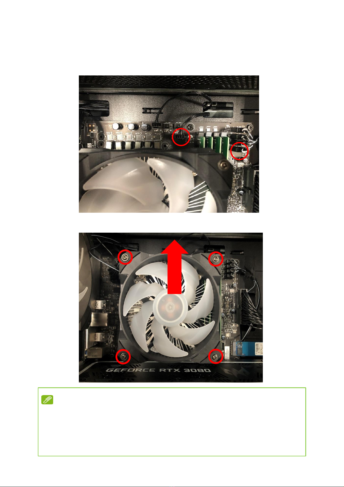
Removing a memory module
1.
Perform Pre-installation instructions on page 6.
2.
Remove CPU fan cable and CPU fan ARGB cable.
3.
Remove four screws for CPU cooler fan
and take it off.
Note
Once the fan is removed, if you want to re-install it back,
you have to apply the thermal grease evenly
Recommended grease part number: TC-5888

Upgrading your Computer -
17
4.
Remove four screws for CPU cooler
and take it off.
5.
Press outward the holding clips on both sides of the
DIMM slot outward to release the memory module (1).
6.
Gently pull the memory module upward to remove it
from the DIMM slot (2).
7.
Repeat steps 2~3 to remove the other memory
modules.
2
1

-Upgrading your Computer
18
Installing a memory module
1.
Select an empty DIMM slot.
2.
Remove the new memory module from its packaging,
handling it by the edges.
3.
Align then insert the memory module into the DIMM
slot (1).
4.
Insert the memory to the slot until the retaining clips
snap inward (2).
The module is keyed so it can only be inserted in one
direction. If the module does not fit, make sure that
the notch in the module lines up with the tab in the
memory slot.
5.
Repeat steps 1~4 to install the other memory modules.
6.
Observe the Post-installation instructions on page 6.
1
2
2
1
Note
DIMM slots on the mainboard must be installed only in certain
configurations. Numbers next to DIMM slots correspond to
installation sequence.
Be sure to install the memory module in DIMM1 slot followed by
DIMM2 slot.
If you would like to upgrade memory, please take off CPU cooler
first.

Upgrading your Computer -
19
Graphics board
The computer contains one or two Graphics board installed
in the PCIe x16 slots. The detail configuration will be
differed by different models.
Removing the Graphics board
1.
Perform Pre-installation instructions on page 6.
2.
Remove four screws for CPU fan cable and CPU fan
ARGB cable.
3.
Remove four screws for CPU cooler fan and take it off.

-Upgrading your Computer
20
4.
Remove four screws for CPU cooler and take it off.
5.
Disconnect the power cables from the Graphics board
6.
Remove the screws that secure the Graphics board to
the chassis
Table of contents


