Important Safety Instructions/Instructions de sécurité importantes Explication des symboles
Explanation Of Symbols/Explication des symboles
L
N
LIVE/PHASE
PROTECTIVE EARTH (GROUND)/
PROTECTION DE MISE A LA TERRE
NEUTRAL/NEUTRE
AC CURRENT/COURANT ALTERNATIF
WARNING/ATTENTION TENSION
DANGEROUS VOLTAGE/DANGEREUSE
PORTABLE CART WARNING/
AVERTISSEMENT LIE AU CHARIOT
PORTATIF
1) Read these instructions./Lisez ces instructions.
2) Keep these instructions./Conservez ces instructions.
3) Heed all warnings./Tenez compte de tous les avertissements.
4) Follow all instructions./Suivez toutes les instructions.
5) Do not use this apparatus near water./N'utilisez pas ce dispositif à proximité d'eau.
6) Clean only with dry cloth./Utilisez uniquement un chiffon sec pour le nettoyage.
7) Do not block any ventilation openings. Install in accordance with the manufacturer's instructions./Ne bloquez pas les orifices d'aération. Installez le
dispositif conformément aux instructions du fabricant.
8) Do not install near any heat sources such as radiators, heat registers, stoves, or other apparatus (including amplifiers) that produce heat./Ne l'installez
pas à proximité de sources de chaleur, telles que des radiateurs, bouches de chauffage, fours ou autres appareils (y compris les amplificateurs) qui
génèrent de la chaleur.
9) Do not defeat the safety purpose of the polarized or grounding type plug. A polarized plug has two blades with one wider than the other. A grounding
type plug has two blades and a third grounding prong. The wide blade, or the third prong are provided for your safety. If the provided plug does not fit
your outlet, consult an electrician for replacement of the obsolete outlet./Ne supprimez pas la fonction de sécurité de la prise polarisée ou de mise à la
terre. Une prise polarisée possède deux lames, dont l'une est plus large que l'autre. Une prise de mise à la terre possède deux lames, et une troisième
broche pour la mise à la terre. La lame la plus large ou la troisième broche ont pour but d'assurer votre sécurité. Si la prise fournie ne s'adapte pas à
votre prise murale, consultez un électricien pour remplacer cette dernière.
10) Protect the power chord from being walked on or pinched particularly at plugs, convenience receptacles, and at the point they exit from the apparatus./
Protégez le cordon d'alimentation afin qu'il soit à l'abri des piétinements ou qu'il ne soit pas écrasé, tout particulièrement au niveau des fiches, des
prises de courant et de sa sortie du dispositif.
11) Only use attachments/accessories specified by the manufacturer./Utilisez uniquement les pièces et accessoires spécifiés par le fabricant.
12) Use only with the cart, stand, tripod, bracket, or table specified by the manufacturer, or sold with the apparatus. When a cart is used,
use caution when moving the cart/apparatus combination to avoid injury from tip-over./Utilisez uniquement le chariot, le pied, le
trépied, le support ou la table recommandés par le fabricant ou fournis avec l'appareil. Si un chariot est utilisé, déplacez l'ensemble
chariot-appareil avec précaution afin de ne pas le renverser, ce qui pourrait entraîner des blessures.
13) Unplug the apparatus during lightning storms or when unused for long periods of time./Débranchez l'appareil en cas d'orage ou si
vous ne l'utilisez pas pendant une période prolongée.
14) Refer all servicing to qualified service personnel. Servicing is required when the apparatus has been damaged in any way, such as power-supply chord or
plug is damaged, liquid has been spilled or objects have fallen in to the apparatus, the apparatus has been exposed to rain or moisture, does not
operate normally, or has been dropped./Confiez l'entretien à un personnel qualifié. L'entretien est nécessaire lorsque l'appareil a été endommagé, par
exemple si le cordon d'alimentation ou sa fiche est abîmé, si du liquide a été versé sur l'appareil ou des objets y ont été introduits, si l'appareil a été
soumis à la pluie ou l'humidité, s'il ne fonctionne pas correctement ou s'il est tombé.
15) To prevent injury, this apparatus must be securely attached to the floor/wall in accordance with the installation instructions./Afin d'éviter les blessures,
cet appareil doit être solidement fixé au sol/mur, conformément aux instructions d'installation.
page 1
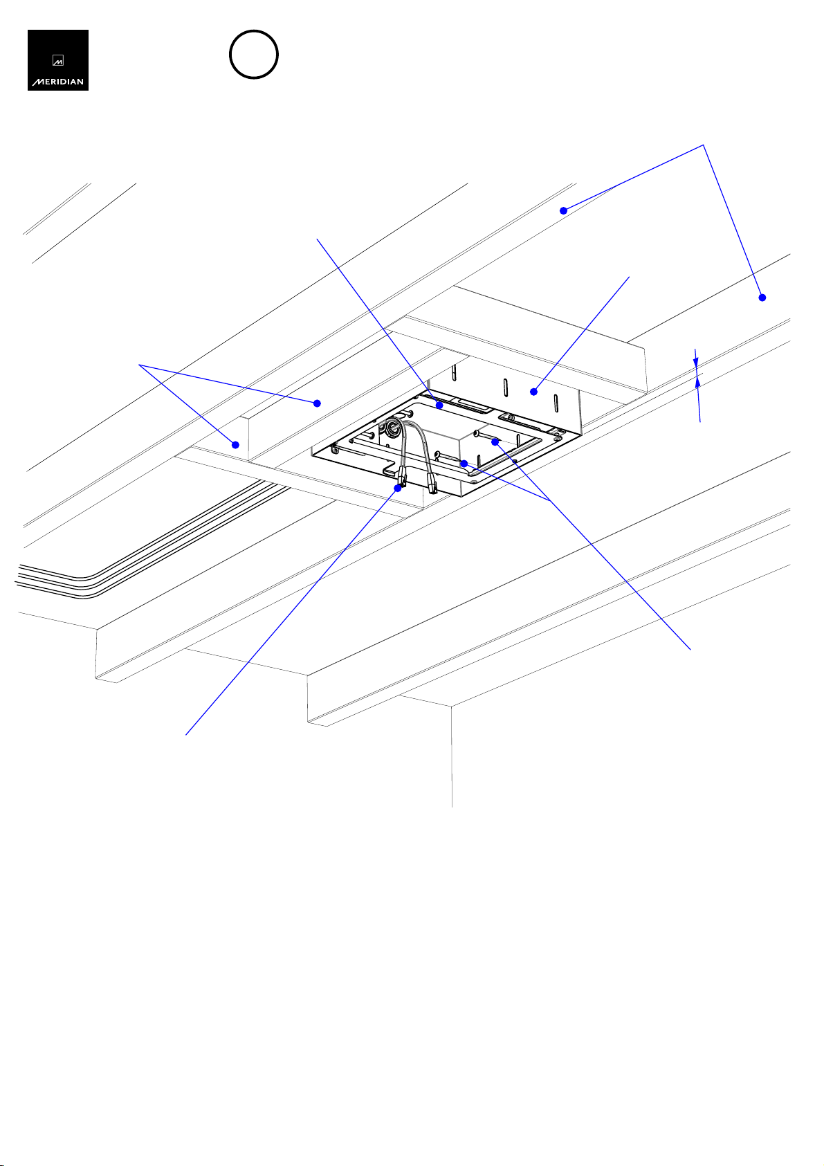
Safety/Sécurité
Guide for wiring the mains to the
Meridian Rough-in box
This equipment is intended for permanent connection to the mains supply.
A skilled and suitably trained person must carry out connection to the mains.
National and local building regulations and electrical requirements must be
adhered to when installing this equipment. Copper conductors should
be used. An all pole mains switch with a contact separation of at
least 3mm in each pole shall be incorporated into the
electrical installation of the building.
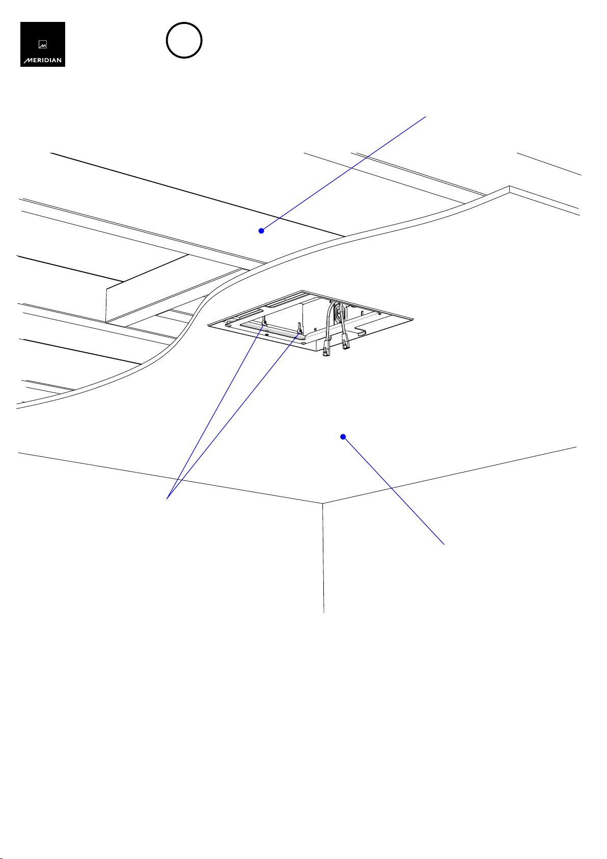
Permanent connection of Meridian Rough-In box to
mains:
1) Isolate the mains before connection.
2) Remove the mains terminal cover.
3) Feed the mains wire through the grommeted hole,
or use a suitable cable-gland in place of the grommet
if the national and local electrical and building
regulations require it.
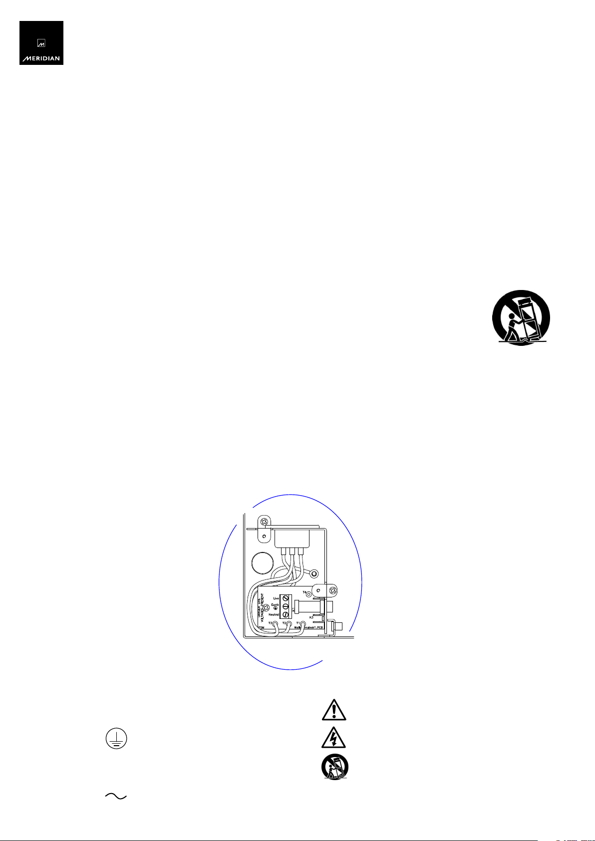
4) Connect to the terminal block on circuit board Neutral,
Earth and Live connections.
5) Replace the mains terminal cover.
Guide du branchement du boîtier
d'encastrement Meridian au secteur
Ce dispositif est conçu pour une connexion permanente à l'alimentation
secteur. La connexion au secteur doit être effectuée par du personnel
qualifié et formé à cet effet. La réglementation nationale ou locale en
matière de construction et d'électricité doit être respectée lors de
l'installation de ce dispositif. Des conducteurs en cuivre doivent être
utilisés. Un interrupteur secteur omnipolaire, avec séparation des
contacts de 3 mm minimum entre chaque pôle, doit être ajouté
à l'installation électrique du bâtiment.
Connexion permanente du boîtier d'encastrement
Meridian au secteur:
1)
Isolez le secteur avant la connexion.
2)
Retirez le cache-borne secteur.
3)
Passez le câble secteur par l'orifice à œillet ou
utilisez un presse-étoupe adapté au lieu de l'œillet
si la réglementation nationale ou locale en matière
de construction et d'électricité l'exige.
4)
Branchez les câbles Neutre, Terre et Phase au
bornier du tableau.
5)
Replacez le cache-borne secteur.
Shown with
cover removed