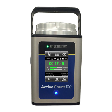
MESA LABORATORIES PQ 200 User manual

Mesa Laboratories, Inc.
12100 West 6th Ave.
Lakewood, CO 80228
.MesaLabs.com
MK101-05 Rev B
PQ 200 Air Sampler
User Manual
U.S. EPA FRM Designated Sampler
PM2.5 RFPS-0498-116
PM10 RFPS-1298-125

NOTICE
This manual pertains to the Revision U(C8445) version of the PQ200. Refer to the table of contents for
information on previous versions of the sampler.
Customer Support and Technical Assistance
For technical assistance or to request repairs or replacement parts, contact Mesa Labs at (973) 492-8400,
or by e-mail at csbutler@mesalabs.com.

3
Table of Contents
Section Page
1.0 Introduction………………………………………………………………………………………………………………………...5
2.0 Instrument Description………………………………………………………………………………………………………… 6
3.0 Specifications……………………………………………………………………………………………………………………..10
4.0 Safety……………………………………………………………………………………………………………………………….10
5.0 Setup
5.1. Initial Setup Instructions……………………………………………………………………………………………………………...10
5.2 Initially Po ering the PQ200……………………………………………………………………………….………………………..15
5.3 Setting the Date and Time…………………………………………………………………………………………………………...15
5.4 Entering Site and Filter Information……………………………………………………………………………………………….15
5.5 Initial Performance Checks……………………………………………………………………………………………………………15
6.0 Operation
6.1 Run the Sampler from Midnight to Midnight……………………………………………………………………….…………...17
6.2 Run the Sampler ith User-Defined Start/Stop Times……………………………………….………………………………18
6.3 While the PQ200 is Running…………………………………………………………………………………………………………..18
6.4 Temporary Halt Then Continue Sampling………………………………………………………………………………………..19
6.5 Ending a Run………………………………………………………………………………………………………………….……………20
6.6 Data Do nload Instructions…………………………………………………………………………………………………………..20
6.6.1 Data Do nload Using USB On-The-Go (OTG) Flash Drive…………………………………………………………20
6.6.2 PQ200 Job Controller Soft are for Windo s……………………………………………………………………………20
6.6.3 Data Do nload Using the PQ200 Menu………………………………………………………………………………….21
6.6.4 Data Do nload Using Serial Communication Commands………………………………………………………….21
7.0 Calibration
7.1 Flo Rate
7.1.1 Flo Rate Calibration…………………………………………………….……………………………………………………23
7.1.2 Verifying Flo Rate……………………………………………………….……………………………………………………24
7.1.3 Changing Flo Rate…………………………………………………………………….……………………………………..24
7.2 Temperature Probe
7.2.1 Verifying Temperature……………………………………………………………………………….……………………….25
7.2.2 Calibrating Temperature………………………………………………………………………………………….………….25
7.3 Barometric Pressure
7.3.1 Pressure Calibration and Verification……………………………………………………………………..………………26
7.4 Leak Tests
7.4.1 External Leak Test……………………………………………………………………………………………………………...26
7.4.2 Internal Leak Test…………………………………………………………………………………………………….………..27
8.0 Maintenance
8.1 Cleaning the Inlet, VSCC, and Do ntube…….…………………………………………………………………………………27
8.2 Rebuilding the Pump…. ………………………………………………………………………………………………………….......27
8.3 Updating Firm are………………………………………………………………………………………………………………………28
9.0 Troubleshooting………………………………………………………………………………………………………………..29
10.0 Warranty………………………………………………………………………………………………………………………….31
Appendix A Parts List and Blo -Out Figures………………………………………………………………………………32
Appendix B PQ200 Sampler Menu Tree…………………………………………………………………………………….47
Appendix C Filters and Weighing Procedure………………………………………………………………………………49
Appendix D Dip S itch Functions……………………………………………………………………………………………..51
Appendix E Use of the PQ200 as a PM
10
Designated Reference Sampler………………………………………54
Appendix F Solar Panel Po er Supply……………………………………………………………………………………….55
Appendix G Accessories…………………………………………………………………………………………………………..62
Appendix H PQ200 Job Controller Soft are……………………………………………………………………………….64
Appendix I Terminal Program Interface……………………………………………………………………………………67
Appendix J Very Sharp Cut Cyclone – VSCC – Instructions for Use and Maintenance…………………….68

4
Appendix K Updating Main Controller Board to “Rev U”………………………………………………………………71
Appendix L Instructions for PMcoarse Sampling…………………………………………………………………………..77
Appendix M Leak Test Procedure for S’Ns 906 through 1016……………………………………………………….79
Appendix N Rev “D” PCBs Calibration and Parts…………………………………………………………………………81
Appendix O WINS Installation………………………………………………………………………………………………….85
Appendix P Pump Rebuild Instructions……………………………………………………………………………………..87
Appendix Q Revision T Manual…………………………………………………………………………………………………97
Figure List
Name Page
Figure 1. Schematic Vie of System……………………………………………………………………………………….9
Figure 2. Exploded Vie of Components Installed in Back of Instrument………………………………....14
Figure A1. Filter Holder ith PM
10
Adapter Installed………………………………………………………………….33
Figure A2. PQ200 Pump Exploded Dra ing……………………………………………………………………………..34
Figure A3. Instrument Panel Exploded Dra ing……………………………………………………………………….35
Figure A4. Components Behind Door………………………………………………………………………………………36
Figure A5. PM10 Size Selective Inlet……………………………………………………………………………………….37
Figure A6. Current Model Cables…………………………………………………………………………………………….38
Figure A7. Current Model Cables…………………………………………………………………………………………….39
Figure A8. Current Model Cables…………………………………………………………………………………………….40
Figure A9. Location of Cable Connections…………………..……………………………………………………………41
Figure A10. Location of Cable Connections on Rev T PCB……………………………………………………………42
Figure D1. Location of Dip S itches………………………………………………………………………………………..51
Figure D2. PQ200 Dip S itch………………………………………………………………………………………………….53
Figure E1. PM
10
Adapter and Filter Holder, Open………………………………………………………………………54
Figure F1. Setup of Solar Panel………………………………………………………………………………………………58
Figure F2. Orientation of Solar Panel………………………………………………………………………………………59
Figure F3. Setting the Tilt Angle…………………………………………………………………………………………….60
Figure F4. Wiring Connections……………………………………………………………………………………………….61
Figure G1. Cassette Opener (CO1)………………………………………………………………………………………….62
Figure G2. Cassette Transport Carrier (F214)…………………………………………………………………………..62
Figure J1. Flo Path in VSCC Cyclone…………………………………………………………………………………….68
Figure J2. Exploded Diagram of VSCC…………………………………………………………………………………….70
Figure K1. Exploded Vie of Obsolete Instrument Panel Configuration………………………………..…….74
Figure K2. Exploded Vie of Instrument Panel…………………………………………………………………………75
Figure K3. Location of Lo Voltage and Ambient Cables on Inside Panel……………………………………76
Figure K4. Location of Pressure Hoses…………………………………………………………………………………….76
Figure N1. Obsolete Cables from Rev D PCB…………………………………………………………………………….83
Figure N2. Obsolete Cables from Rev D PCB…………………………………………………………………………….84
Figure P1. PQ200 Pump Exploded Dra ing……………………………………………………………………………..95
Figure P2. Orientation of Valve Plates……………………………………………………………………………………..96
Figure Q1. Location of temperature probe trimpots on Rev T PCB………………………………………………22

5
1 0 Introduction
The purpose of this manual is to provide complete operation, calibration, and maintenance details for the
BGI PQ200 air sampler. This instrument has been specifically designed to meet or exceed the operational
requirements of a Reference Method sampling device under 40 CFR Part 50, Appendices J and L. For
additional guidance on sampler operation, recommended maintenance, and procedures for filter handling
and eighing, refer to the EPA Quality Assurance Handbook Volume II
1
.
The PQ200 is a microprocessor-controlled air sampling instrument capable of sampling TSP, PM
10
, and
PM
2.5
over user-defined volumetric flo rate and sampling period. The PQ200 includes an internal battery,
hich allo s the investigator to perform their ork in areas here no line po er is available. DC po er
operation can be further augmented ith a po er supply/charger, or external batteries and solar po er.
Further details about solar po er operation are available in Appendix F. Recovered data may be handled
ith provided Windo s soft are. The instrument is manufactured entirely in the U.S. in an ISO 9001-
certified facility in Butler, Ne Jersey.
Current Models
Part Number Description
PQVSCC PQ200 PM
2.5
Sampler - The PQ200 configured for PM
2.5
sampling includes a BGI Very Sharp Cut Cyclone (VSCC
TM
)
and PM
10
louvered inlet head. This instrument as
designated as a PM
2.5
sampler under Federal Reference
designation number RFPS-0498-116.
PQ200PM10 PQ200 PM
10
Sampler - The PQ200 configured for PM
10
sampling includes a PM
10
louvered inlet head and a straight
passage replacing the VSCC
TM
or WINS. This instrument
as designated as a PM
10
sampler under Federal Reference
designation number RFPS-1298-125.
PQVSCC and
PQ200PM10
The PQ200 PM
Coarse
Samplers - The PQ200 may also be
configured for sampling the PM Coarse (PM
Coarse
). PM
coarse
is
defined by the U.S. EPA as the size fraction bet een PM
10
and PM
2.5
. This measurement requires t o PQ200
samplers, one for PM
10
and one for PM
2.5
. Specific
instructions for operating instruments to perform these
measurements are described in Appendix K.
Legacy Model
The PQ200A PM
2.5
Audit Sampler - PQ200A is a legacy version of the PQ200 sampler including transport
cases and limited enclosure modifications. The PQ200A model is covered under the original designation
as amended August 1998.
1 U.S. EPA Quality Assurance Handbook for Air Pollution Measurement Systems:
http:// .epa.gov/ttnamti1/files/ambient/pm25/qa/QA-Handbook-Vol-II.pdf

6
2 0 Instrument Description
Your PQ200 comes ith the follo ing:
PQ200 sampler
Do ntube
PM
10
inlet ith ater jar
VSCC or PM
10
adapter installed in filter assembly (model dependent)
12V battery
Filter cassette
AC po er adapter
Legs (3)
Ambient temperature sensor ith radiation shield
Leak test kit (flo audit adapter and filter cassette plus rubber discs)
Do nload cable
The components and basic instrument operation are as follo s:
Inlet The louvered size-selective inlet is manufactured according to design dra ings
and specifications in 40 CFR 50 Appendix L. It is designed to operate
independently of ind direction and ind speed, ith a throughput of 16.7 LPM.
The louvered design and ind deflector hinders rain intrusion. An enlarged ater
exit hole in the impactor plate is used to promote ater flo to the ater
collection jar.
Do ntube The do ntube, also specified by design dra ings in 40 CFR 50 Appendix L,
transports the aerosol from the inlet to the filter assembly.
VSCC The Very Sharp Cut Cyclone (VSCC
TM
) as designed by BGI as a replacement to
the WINS PM
2.5
separation impactor. Per 40 CFR 50 Appendix L, the VSCC may
be used in any FRM device as a PM
2.5
particle size selector. The VSCC
TM
-B model
is designed to fit the filter assembly of the PQ200. When sampling PM
10
, the PM
10
adapter should be used in place of the VSCC
TM
. All PQ200 ith a PM2.5
configuration ill come standard ith a VSCC.
PM
2.5
WINS Impactor The WINS (Well Impactor Ninety-Six) PM
2.5
impactor is described by dra ings
and specifications in 40 CFR 50 Appendix L. The ell impactor, hen properly
operated ith a 37 mm glass fiber filter and 1 mL of Do 704 diffusion oil in the
ell, is designed to operate for approximately one eek, depending on the
ambient concentrations, ithout overloading or alteration of the cutpoint or
collection efficiency curve. Most modern PM
2.5
samplers use the VSCC over the
WINS. The WINS is no longer produced by Mesa Labs.
PM
10
Adapter For PM
10
sampling, the PQ200 uses an adapter to provide a straight passage to
the filter. This adapter is a direct replacement for the VSCC-B and is approved for
PM10 sampling by the U.S. EPA under Federal Reference designation number
RFPS-1298-125.
Filter Holder The filter holder and filter cassette are manufactured per the dra ings in 40 CFR
50 Appendix L. The upper filter holder housing is designed into the same piece
as the VSCC-B. The lo er section houses the filter temperature probe and the air
hose connection, hich leads to the pump system. O-rings on the upper and

7
lo er housings ensure a tight seal around the filter cassette. The filter cassette
itself is made of Delrin
®
and has upper and lo er sections hich snap together.
These t o halves sand ich a single 47 mm filter and a stainless-steel screen
hich serves as a backing/support plate for the filter. To ensure a tight seal, the
filter cassette as designed ith an interference fit hich can initially make
opening and closing the cassette difficult. Practice is recommended so that the
cassette may be opened ithout damaging or dropping the filter.
Flo System The flo system of the instrument is schematically illustrated in Figure 1. The
configuration from the size selective inlet to the filter holder is mandated for
Reference Methods under 40 CFR Part 50 Appendix L. From the filter holder, air
flo s through an interception ater separator. The separator is fitted ith a
clear elastomeric tube located in the right, rear of the instrument case behind
the filter holder. The bottom of this tube is fitted ith a push valve on the
bottom/outside of the case to permit the draining of ater collected in the clear
tube. The flo of air is directed through the mass flo sensor and then to a
pulsation dampening volume. Prior to the pump, the air passes through the
solenoid valve. The sole purpose of this valve is to provide a means of sealing
the far end of the system hen the automatic leak check function is activated.
The pump is a Mesa-manufactured, double diaphragm unit designed especially
for this instrument.
A microprocessor controls the flo system. The mass flo sensor detects the
mass flo rate through the unit, from hich the microprocessor then computes
the volumetric flo rate utilizing the current barometric pressure and ambient
temperature.
The algorithm used for this process is:
= Q
∗
∗
Where:
Q
vol
is the current volumetric flo rate in liters per minute
Q
cal
is the calibrated volumetric flo rate in liters per minute
(calibrate at 16.67 LPM for EPA sampling)
T
vol
is the current ambient temperature (K)
T
cal
is the calibration ambient temperature (K)
P
vol
is the current ambient barometric pressure in mmHg
P
cal
is the calibration barometric pressure in mmHg
While the sensor is detecting the mass of air flo ing, the calibration device
utilized is volumetric. The microprocessor is logging a mass flo rate along ith
barometric pressure and temperature at the time of calibration. The firm are in
the microprocessor calculates a volumetric flo rate based on current actual
conditions. This calculation and control adjustment is updated every 200
milliseconds.
Temperature Sensors Temperature measurement is accomplished ith a linearized thermistor circuit. A
shunt resistor (R1) in series ith a precision thermistor ith a negative
temperature coefficient (TH1) decreases the rate of resistance change as

8
temperature decreases. When used as a voltage divider, this circuit ill produce
a linear output voltage proportional to temperature. Resistor R2 and thermistor
TH2 provide compensation for the typically narro range of this simple approach
providing a total accurate range of -30° to +50° C ith a linearity deviation of
+/- 0.16° C.
Pressure Measurement Ambient barometric pressure is measured using a precision temperature-
compensated absolute pressure transducer. Its amplified output is signal-
conditioned to obtain a voltage that is compatible ith the PQ200 A/D converter
and maximizes resolution by spanning the desired range across the A/D
converter’s input range. The inlet port of the barometric sensor is vented to
outside the PQ200 case to eliminate errors due to case pressurization.
Unit Controls Complete control of the sampler is achieved through only six buttons.
ON/OFF
SELECT EXIT LIGHT
The buttons have these functions:
ON/OFF: po ers the PQ200 on and off
UP/DOWN ARROWS: navigate through menu items
SELECT: chooses the current selection
EXIT: hen available, it serves as the “back” or “exit” button
LIGHT: lights the screen hen operating on battery po er
Po er The PQ200 as designed to operate from a nominal 12 Volt DC source. Alternate
po er and battery charge is supplied via a standard, UL listed, class VI po er
supply. Auxiliary po er can also be supplied via an external battery and/or solar
panel to provide operation in remote areas.
When Operating from Batteries
The display ill sho Bty xx% ( here xx = 00 to 99) and indicates approximate capacity. When the

9
Charger/External po er supply is plugged in, the screen ill display [DC In] or toggle bet een [DC In]
and [Charged] depending on the internal battery status. While running from external batteries, the
display ill sho EXT xx% indicating the approximate capacity of the external battery. A s itching circuit
ithin the PQ200 ill automatically detect ho the unit is po ered and ill display appropriately. When
using an external battery, the PQ200 ill drain the external battery first until cut-out occurs at
approximately 10.5VDC to prevent deep discharge. At this point, the internal battery ill then be
s itched into use. If the external battery is being charged by a solar panel, the unit ill automatically
s itch to being po ered by the external battery once it attains a charge of approximately 50%.

10
3 0 SPECIFICATIONS
PQ200 sampler eight: 48 lbs (21.8 kg)
Inlet and do ntube eight: 5.5 lbs (3.4 kg)
Legs eight: 8 lbs (3.6 kg)
Complete system eight: 61.5 lbs (27.9 kg)
Enclosure Dimensions: 16 x 19 x 18 inches (41.1 x 48 x 47 cm)
Height of inlet above ground: 6.56 ft (2 m)
Display: LCD screen
Data Port: RS-232
4 0 SAFETY
The PQ200 should only be operated as described and for its intended use. Because the PQ200 runs
primarily from battery po er, all the typical hazards associated ith high voltages and internal AC iring
have been reduced or eliminated. Personal injury, damage to the instrument, or fire can occur if the
follo ing electrical precautions are not observed:
•Caution should al ays be given hen attaching the AC mains po er connection. Do not attempt
to connect main po er if the plug or ire are cracked or frayed.
•Do not attempt to connect main po er if the po er cord, leads, or outlet are et. Do not
immerse po er cords in ater or other liquids.
•Place po er cords a ay from traffic and do not allo anything to rest on them during operation.
•Do not overload AC outlets.
•Do not attach improperly- ired external batteries, solar panels, or po er sources.
•Allo a fe inches for ventilation at the rear of the instrument. Do not allo the fan opening to
become clogged or blocked.
•Do not open the control panel or handle any other of the electrical parts hile po er is applied to
the PQ200. Al ays disconnect the po er supply first.
•Al ays operate the PQ200 in a normal, upright position. The legs should be bolted do n to
prevent tipping in conditions of high inds.
•Do not operate the PQ200 if any of the parts are defective, damaged, or missing.
5 0 Setup
5 1 Initial Setup Instructions
When you first receive your PQ200, unpack all of the components to ensure that you received all of the
correct parts and nothing as damaged during shipment. It is recommended that each PQ200 sampler
be assembled initially in a laboratory or other environment to check operation prior to installation in the
field.
Follo these steps to set up your PQ200 sampler:

11
Step 1 Attach the legs to the unit at the three
hard points on the underside of the sampler. The
legs are identical and interchangeable. Make sure
the connectors are seated properly and that the legs
are securely attached.
Step 2 Attach the AC po er supply to the rear of the
unit underneath the fan co ling. Use the plate on the AC
po er supply to hook it to the rear of the instrument. Run
the female, three-pin connector underneath the sampler to
the hole in the sampler case near the front on the right
side. Open the main door on the PQ200 and feed the
connector through the hole and attach it securely to the
upper of the t o connectors.
Alternatively, the unit may be operated from the battery
backup system or a solar po er system. When fully
charged, battery po er is sufficient to operate the PQ200
for 24 hours in all but the most extreme conditions. Note
that hen operating from battery po er, the control screen
dims and it may be necessary to press the LIGHT button to
vie the screen. If using the solar po er attachment, the
connector attaches to the PQ200 in the same fashion as the
AC po er supply.

12
Step 3 Attach the external temperature gauge to the
rear of the unit. The attachment points are on the fan
co ling itself. Position the temperature gauge assembly so
that it sits above the top of the sampler case. Scre the
connectors firmly into the attachment points. Run the cord
ith the three-pin connector underneath the sampler case
and through the hole, just as ith the po er connector,
and attach it to the lo er of the t o connectors.
Step 4 Confirm the presence of t o O-rings on the
bottom end of the do ntube that mates ith the open
tube on the top of the sampler case. Ensure the interior of
the tube is clean and clear of any debris. Install do ntube
on sampler.
Step 5 Confirm the presence of t o O-rings on the bottom side of
the size selective inlet that mates ith the do ntube. Install on top of
do ntube. The ater collection hard are is packed separately to avoid
shipping damage. Locate and attach to the side of the size selective
inlet.

13
Step 6. The VSCC assembly is installed prior to
shipment ith model PQVSCC. Open the VSCC and filter
assembly inside the PQ200 sampler case by carefully
rotating the handle counterclock ise using both hands.
Inspect the VSCC for obvious missing pieces or damage.
Ensure the interior of the VSCC is clean and clear of any
debris.
Step 7 The filter holder assembly and filter cassette is installed prior to shipment. Inspect the
filter housing and filter cassette for obvious missing pieces or damage. Confirm the presence of O-
rings inside the upper and lo er filter housings here they contact the filter cassette. Ensure the
housing interior is clean and free of debris.
Step 8 If you are going to immediately run the PQ200, place a filter inside of the filter cassette.
Firmly pull the hite rings apart and place a clean filter on top of the filter screen. Ne filter
cassettes can be difficult to open the first fe uses. Never t ist the filter cassette rings to open ith
a filter installed as this ill damage the filter. Reinstall the filter cassette in the filter housing.

14
Figure 2. Exploded Vie of Components Installed in the Back of the Instrument

15
5 2 Initially Powering the PQ200
Press the ON/OFF button on the PQ200. The screen should light ith the message:
PQ200 Air Sampling System
(c)Copyright 1998 BGI Incorporated
All Rights Reserved
Serial Number: XXXX
Version: X.XX
After a fe seconds, the main screen ill appear. The main screen al ays displays the ambient
barometric pressure, ambient and filter temperatures, date, time, po er source, and any flags that may
have occurred. Any error or status messages ill also appear on the screen. For example:
READY FOR NEW RUN!
746mmHg A 28.0°C F27.5°C
[DC IN]
2016
04jul
(MENU) 14:53
Confirm that the date and time displayed are accurate. If necessary, follo the steps in Section 5.3 belo
to set the proper date and time.
Press SELECT on the control panel to enter the main menu.
5 3 Setting the Date and Time
•From the home screen, press SELECT to access the main menu.
•From the main menu, scroll do n by pressing the do n arro button and select Set Date and
Time by pressing SELECT.
•The Set the current DATE & TIME message ill be displayed. The current date and time ill
be flashing.
•The unit that is flashing can be edited by pressing the Up or Down arro s. Use these arro s to
increase or decrease the selected value.
•After you have selected the desired value, press SELECT to move to the next value you ish to
edit.
•Continue to press the SELECT and Up and Down arro buttons in this fashion to enter the
desired date and time. When done, press the EXIT button to return to the main menu.
•Press the EXIT button again to return to the home screen.
5 4 Entering Site and Filter Information (optional)
1. From the home screen, press SELECT to access the main menu.
2. From the main menu, scroll do n by pressing the do n arro button and select Site & Filter
Information.
3. The first character (T) of the second line has a flashing cursor on it.
4. Using the Up and Down arro buttons, cycle through the possible characters. To select the
flashing character and move to the next character, press the SELECT button. When all
information has been entered, press the EXIT button to return to main menu.

16
5. Press the EXIT button again to return to the home screen.
NOTE: The site and filter information may also be entered using the PQ200 Job Controller soft are
(Appendix H), through OTG Flash Drive (section 6.2), or through the computer using a terminal program
(Appendix I).
5 5 Initial Performance Checks
We recommend the operator perform a series of performance checks after installation and before
operating the instrument for the first time. These checks include an external and internal leak check and
temperature, pressure, and flo verifications.
CAUTION! Do not operate the system without a filter installed
Leak Check
Leak checks should be performed at regular intervals. The U.S. EPA recommends an external and internal
leak check every 5 sampling events
1
. To perform a leak check on the PQ200, follo the detailed
instructions in Section 7.4 of this manual.
Temperature and Pressure Verification
Check the readings of the ambient temperature and barometric pressure gauges against NIST-traceable
devices (see Sections 7.2 and 7.3 of this manual) each time the sampler is operated. Refer to 40 CFR 50
Appendix L for acceptable tolerances. If recalibration is necessary, follo the procedures in Sections
7.2.2 and 7.3.1 of this manual.
Flow Rate Verification
A verification of the sampler flo rate should be performed on a regular schedule; refer to Section 2.12
of EPA’s QA Handbook for the suggested frequency and acceptable tolerances. Section 7.1.2 of this
manual provides instructions on ho to verify the PQ200's flo rate.
1 Quality Assurance Guidance Document 2.12, U.S. EPA, November 1998,
http:// .epa.gov/ttn/amtic/files/ambient/pm25/qa/m212covd.pdf

17
6 0 Operation
6 1 Run the Sampler from Midnight to Midnight
For most applications, this is the appropriate method of operation. It complies ith the EPA’s requirement
for 24-hour sampling. The run ill commence at the next occurrence of midnight (00:00) and ill stop
sampling at midnight of the follo ing day. To run the sampler ith user defined start/stop times, follo
instructions in section 6.2.
Data from a previous run should already have been do nloaded prior to use of
this function
. Ho ever, the instrument ill alert the operator if the data has not been do nloaded.
•From the Main menu, select * Run Sampler from Midnight to Midnight.
•If the user has already do nloaded the previous run data, the follo ing message ill be
displayed:
Run is Scheduled
PQ200 Shutting Down
The PQ200 is then programmed to po er itself on and begin sampling at midnight. If you turn on the
PQ200 back on before the run is scheduled to begin, the main screen ill read WAITING RUN TIME
EVENT!
If you ish to cancel your scheduled run, turn on the PQ200 and enter the main menu. Scroll do n using
the Down arro button and select *Reset Run Data & Scheduled Run
6 2 Run the Sampler with User-Defined Start/Stop Times
6 2 1 Setting User-Defined Start/Stop Times Using PQ200 Menu
If operation other than midnight to midnight sampling is desired, start and stop times can be
programmed. As above, data from a previous run should be do nloaded prior to setting up a sample run.
Ho ever, the instrument ill alert the operator if the data has not been do nloaded.
•From the home screen, press SELECT to access the main menu.
•From the main menu, scroll do n by pressing the do n arro button and select Run with User
Defined Start & Stop
•Set Sample START DATE & TIME and Set Sample STOP DATE & TIME ill be displayed.
The current selection ill be flashing on the second line.
•Use the Up and Down arro buttons to increase or decrease the selected value. When done,
press SELECT.
•Continue to press the SELECT and Up and Down arro buttons to enter the desired date and
time.
•When you are finished setting the start date and time, press the EXIT button to continue.
•If you have not entered a valid date and time, the follo ing message ill be displayed:
Please, Enter Valid Date & Time
Press UP, DOWN, or SELECT to Continue
Setup Procedure for the PQ200 using a flash drive
To adjust settings in your PQ200 using a USB, you ill need a USB On-The-Go (OTG) flash drive. This

18
procedure ill not ork if another type of USB is utilized. To adjust PQ200 settings, follo the steps
belo :
1. Open Notepad on your computer.
2. The document MUST start ith <begin> and end ith
<end>.
3. Write values that you ould like to customize. The options
are listed belo :
a. language: language of operation, English or Spanish
b. filter: filter information, 32 symbols
c. site: site information, 32 symbols
d. logger: logger interval, 30sec or from 01min to
99min
e. flo : flo rate, from 5.0 to 20.0
f. date: current date in dd/mm/yyyy format
g. time: current time in hh:mm:ss format
h. stardate: run start date in dd/mm/yyyy format
i. starttime: run start time in hh:mm:ss format
j. stopdate: run stop date in dd/mm/yyyy format
k. runstoptime: run stop time in hh:mm:ss format
l. runscheduled: run is scheduled? 1=yes, 0=no
m. reset: clears previous run data. 1=yes, 0=no
4. Once the setup data is complete and to your liking, save the file to your USB OTG flash drive
under this specific name and file format(case sensitive):
a. pq200settings.cfg
5. Eject the flash drive from the computer.
6. Turn the PQ200 sampler on. Take the thumb scre s out of the front panel assembly and gently
pull the panel for ard to expose the circuit board (see figure A3).
7. Connect the USB OTG flash drive to the USB type A jack in the PQ200 circuit board.
8. Shortly after the flash drive is connected, the instrument ill beep and the screen ill display
“Do nloading!”, and the PQ200 ill start to load the settings file automatically. If the load is
successful, one of t o things ill happen:
a. If you scheduled a run, the PQ200 ill po er off.
b. If you did not schedule a run, the PQ200 ill return to the home screen.
9. If the do nload as not successful, the changes ill not be seen on the unit. Indicators that the
do nload as not successful are incorrect dates and/or times, no scheduled runs, or any settings
that you rote in Notepad not being reflected by the PQ200.
Note: you do not need to include all of the fields. If you need to adjust the date and time in your PQ200
but do not need to schedule a run, you can just utilize the date and time fields (bracketed by <begin>
and <end>). An example of a pq200settings.cfg file used for adjusting the PQ200 settings can be seen
belo :
6 3 While the PQ200 is Running
While the PQ200 air sampler is running, the display ill look similar to this:
ET000:05 TV:000 08M3 [DC In]
Start:04jul15:00 Stop:05jul15:00
Q(Vlpm):16 70 AVG:16 71 CV 0 16
749mmHg A28 6°C F27 8°C SP025cm
2017
04jul
15:05

19
Pressing the select button ill display a second screen:
Tmax:28 5 Tmin:28 2 Tavg:28 4
BPmax:750 BPmin:749 BPavg:749
Q(Vlpm):16 70 AVG:16 71 CV 0 16
749mmHg A28 6°C F27 8°C SP025cm
2017
04jul
15:05
Where:
ET: elapsed time since the current run started
TV: total volume sampled during the current run
[DC In]: current po er source from hich the sampler is operating
Start: the time and date the current sample started
Stop: the time and date the current sample stopped (or is set to stop)
Q(Vlpm): the instantaneous flo rate in liters per minute
AVG: average flo rate, liters per minute
CV: coefficient of variation of flo rate
mmHg: instantaneous ambient barometric pressure, millimeters of mercury
A ° C: instantaneous ambient temperature in degrees Celsius
F ° C: instantaneous filter temperature in degrees Celsius
SP cm: pressure drop across the filter, in cm H
2
O
Tmax: the maximum ambient temperature measured during the run
Tmin: the minimum ambient temperature measured during the run
Tavg: the average ambient temperature
BPmax: the maximum barometric pressure measured during the run
BPmin: the minimum barometric pressure measured during the run
BPavg: the average barometric pressure
Flags hich may appear in the upper right corner of the screen. The follo ing flags are possible:
P indicates that a po er failure has occurred
Q indicates that flo has varied more than +/- 5 percent
F indicates that a 5 degree filter overheat lasting more than 30 minutes has occurred
T indicates that the sample ran less than 23 hours 50 minutes
M indicates memory overflo (max run time ith 5 minute logger interval)
During operation, the SELECT button provides alternate displays of minimum, maximum, and average
ambient temperatures and barometric pressures or other run time data hile the ON/OFF button ill
temporarily suspend the run. The run is not considered complete until the Sample Stop Date and Time
have been attained.
6 4 Temporary Halt Then Continue Sampling
Per the U.S. regulations for PM
2.5
sampling, samples must be taken from at least 23 but not more than 25
hours. In the event that it becomes necessary to temporarily halt a sample in progress, simply press the
ON/OFF button. The unit ill return to the main menu and display:
Halted by Operator!
To continue ith the current sample run,

20
•From the home screen, press SELECT to access the main menu.
•From the main menu, scroll do n by pressing the do n arro button and select * Continue
Current Run
The sampler ill then resume the run. Ho ever, observe that the elapsed time did not change hile the
unit as halted. At the end of the 24-hour sample period, if elapsed time is less than 23 hours 50
minutes, the T flag ill be displayed. Ho ever, per the U.S. regulations, samples bet een 23 and 25
hours are valid.
6 5 Ending a Run
When the PQ200 has completed its run, the display ill sho :
SAMPLE RUN COMPLETED!
751mmHg A28 1°C F27 4°C
2015
05jul
(MENU) 15:02
The filter may no be removed.
6 6 Data Download Instructions
When the sampler has completed its run, the data may be do nloaded from the PQ200. Be sure to
do nload the most recent run before setting the sampler to start another run. For user convenience, the
PQ200 allo s for several different methods to perform this task.
6 6 1 Data Download Using USB On-The-Go (OTG) Flash Drive
To do nload ith a USB OTG, follo the steps belo :
1. To access the USB jack, unscre the top button scre s on the instrument panel assembly (part
85 in Figure A3).
2. After the scre s are removed, gently pull the panel for ard, exposing the circuit board. Be sure
not to pull on any ire connections, and not to expose the circuit board to rain or moisture.
3. Plug the USB OTG flash drive into the USB type A jack.
4. After a beep, the do nloading ill start automatically, and the screen ill sho Downloading!
5. When complete, the display ill return to the home screen or turn off if you have scheduled a
run.
6. After you have do nloaded the data on your USB, the file name ill have the serial number and
run date as the file name (i.e., 00001_18jan01.job, here 00001 is the serial number and
18jan01 is the date of the sampling run in yymmmdd format).
6 6 2 PQ200 Job Controller Software for Windows
To extract the run data, a computer ith the PQ200 Do nloader soft are loaded and a female-female
serial cable are required. Section 4.0 also contains greater detail about the other features of the PQ200
Job Controller soft are.
This manual suits for next models
4
Table of contents
Popular Sampler manuals by other brands
Endress+Hauser
Endress+Hauser Liquistation CSF34 Brief operating instructions
Sentry
Sentry DPA S-CM-IOM-00557-0 07-20 Installation, operation & maintenance manual
Roland
Roland SP-404MK2 Reference manual
YZ Systems
YZ Systems DynaPak 2010N Series manual
PIONEER DJ
PIONEER DJ DJS-1000 operating instructions
Atec
Atec 8001 Operation and maintenance manual
