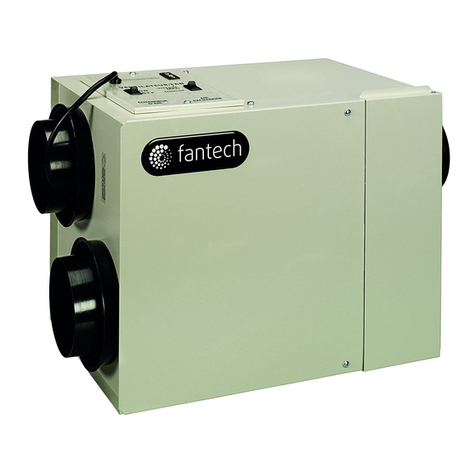
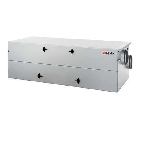
Messana ATU150H User manual

Vertical and horizontal Air Treatment Units (ATU)
Neutral Temperature Dehumidifier (NTD) with high efficiency heat recovery ventilation (HRV)
M A I N T E N A N C E , I N S T A L L A T I O N
A N D U S E R M A N U A L

Air Treatment Unit
2 Maintenance, installation and user manual –Rev 03
Each unit comes with “Installation and Operation Manual” (this manual) and additional
documents:
Cutsheet (it includes dimensional drawings and clearances)
Wiring diagram
The reproduction of this document, even partial, without Messana Inc. written authorization, is strictly forbidden

Air Treatment Units
Maintenance, installation and user manual –Rev 03 3
ATU
Neutral Temperature Dehumidifier (NTD) with high efficiency heat recovery ventilation (HRV)
BEFORE USING THIS UNIT, READ CAREFULLY THIS MANUAL
Dear Customer,
Thank you for having chosen one of our products.
We are glad to provide this User Manual to you, in order to allow an optimum usage of the unit, for a better
comfort and a higher safety.
We strongly recommend a careful reading of the directions mentioned in the following pages and to let the
present manual available to all the operators who will work for the management and the maintenance of the
unit itself.
We remain at your disposal for any further information and explication you may need, whether in the first
starting phase and in every following moment.
For necessary ordinary or extraordinary maintenance operations, we remain at your disposal with our
Technical support Service, to assist you and supply the spare parts.
For a quicker assistance, please contact us at the following references:
MESSANA RADIANT COOLING
radiantcooling.com
4105 Soquel Ste B, Soquel CA 95073
+1 (855) RAY-MAGIC (729-6244)

Air Treatment Unit
4 Maintenance, installation and user manual –Rev 03
SUMMARY
1INTRODUCTION ............................................................................................................................. 5
1.1 RESPONSABILITIES ................................................................................................................................................................. 5
1.2 SERVICE RULES....................................................................................................................................................................... 7
1.3 USES ...................................................................................................................................................................................... 7
1.4 RESIDUAL RISK AREAS............................................................................................................................................................ 8
1.5 INTERVENTION AND MAINTENANCE ..................................................................................................................................... 8
1.6 GENERAL SAFETY RULES ........................................................................................................................................................ 9
2PRODUCT DESCRIPTION ................................................................................................................10
2.1 SERIES .................................................................................................................................................................................. 11
2.2 AIR FLUXES........................................................................................................................................................................... 12
2.3 STRUCTURE ......................................................................................................................................................................... 20
2.4 OPERATING LIMITS .............................................................................................................................................................. 20
2.5 FUNCTIONS.......................................................................................................................................................................... 21
3REFRIGERANT AND HYDRAULIC CIRCUITS ......................................................................................22
3.1 FUNCTIONAL SCHEMES ....................................................................................................................................................... 22
3.2 PROJECT CRITERIA ............................................................................................................................................................... 22
4ELECTRICAL CIRCUITS ....................................................................................................................23
4.1 ELECTRICAL DEVICES............................................................................................................................................................ 23
5DISPLAY........................................................................................................................................23
5.1 KEYS..................................................................................................................................................................................... 23
5.2 MAIN SCREEN ...................................................................................................................................................................... 24
5.3 USER MENU ......................................................................................................................................................................... 24
5.4 ALARMS MENU.................................................................................................................................................................... 27
5.5 UNIT STATUS MENU ............................................................................................................................................................ 27
5.6 TIME BANDS MENU ............................................................................................................................................................. 28
5.7 OTHER SCREENS................................................................................................................................................................... 29
6TECHNICAL DATA ..........................................................................................................................30
6.1 TECHNICAL DATA SHEET ...................................................................................................................................................... 30
6.2 AIRFLOWS AND PRESSURE................................................................................................................................................... 34
6.3 DEHUMIDIFICATION PERFORMANCE .................................................................................................................................. 36
6.4 HYDRAULIC CIRCUIT LOAD LOSSES ...................................................................................................................................... 38
7HEATING CAPACITY –MODEL I ......................................................................................................40
8MAINTENANCE AND TROUBLESHOOTING......................................................................................41
8.1 FAULTS AND ANOMALIES .................................................................................................................................................... 41
8.2 MAINTENANCE TABLE ......................................................................................................................................................... 43
8.3 ORDINARY MAINTENANCE .................................................................................................................................................. 44
8.4 EXTRAORDINARY MAINTENANCE........................................................................................................................................ 46
9DISMANTLING OF THE UNIT ..........................................................................................................46
9.1 AMBIENT PROTECTION........................................................................................................................................................ 46
10 INSTALLATION ..............................................................................................................................47
10.1 INTRODUCTION ................................................................................................................................................................... 47
10.2 PLACEMENT......................................................................................................................................................................... 47
10.3 CLEARANCES........................................................................................................................................................................ 48
10.4 HYDRAULIC CONNECTIONS.................................................................................................................................................. 50
10.5 ELECTRICAL CONNECTIONS ................................................................................................................................................. 51
10.6 FIRST STARTING, CALIBRATION AND CONFIGURATION ....................................................................................................... 54
FOR THE DIMENSIONAL DRAWINGS, SEE THE DRAWINGS ATTACHEMENT

Air Treatment Units
Maintenance, installation and user manual –Rev 03 5
1INTRODUCTION
The present MIUM indicates the uses of the unit and gives instructions for transport, installation, assembling and regulation of the
unit. It gives directions about maintenance, spare parts’ request, residual risks presence and staff education.
This manual should be read and used in the following way:
-Each operator and person concerned with the use and maintenance of the unit, should read it carefully and follow the
instructions it gives;
-the employer has to verify that the operator has the required attitudes to conduct the unit and that he has carefully read
the manual; the employer is also supposed to inform the operator about the risks of accidents, mainly risks deriving from
the noise, the individual protection devices and the rules preview according to the law, both at an international level and at
the destination Country level;
-the manual should always be available for the user, the supervisors, the transport Company, the operators for the
placement, the maintenance, the reparation and the dismantling of the unit;
-the manual should be protected from humidity and hot zones and considered as an integrant part of the unit for all its
lifetime; it has to be delivered to any other user or the next owner of the unit;
-please make sure that every update is included in the manual;
-do not damage, remove, strip or re-write the manual, neither part of it; in case it is lost or damaged, please contact the
manufacturer for the request of a new user manual and communicate the matriculation number of the unit (you find it on
the data label).
Please, take care of the following symbols. Their function is to underline the following information:
It makes reference to dangerous situations that can occur when using the machine, in order to
grant people safety.
It makes reference to dangerous situations that can occur when using the machine, in order to
avoid damages to the unit itself and to things around it.
It makes reference to suggestions or additional integration for a correct use of the unit.
The manufacturer has the right to update products and relative manuals, without being obliged to update previous versions, with
exception of particular cases.
This manual refers to the current technologies adopted at the moment of the selling of the unit and cannot be considered
inadequate according to following updating due to technology evolutions.
To ask for eventual manual updating or for integration, please forward your request to the previously indicated references.
Please contact the manufacturer for further information or suggestions.
In case of re-selling of the unit, please inform the manufacturer about the new owner references, in order to facilitate the
communication between the both of us.
1.1 RESPONSABILITIES
The unit is granted according to the contract clauses subscribed in the sales negotiation.
The manufacturer is not responsible for accidents that can occur because of:
-the non-following of the instructions given in this manual about the correct use,
maintenance and first-starting of the machine;
-changes made in the unit or in the safety devices without a written authorization from the
manufacturer;
-non-authorized attempts of repair;
-negligence in constant maintenance or use of non-original spare parts;
Anyhow, if the user accuses the manufacturer for any fault of the unit, he has to demonstrate that the damage occurred has been a
direct consequence of the supposed fault.

Air Treatment Unit
6 Maintenance, installation and user manual –Rev 03

Air Treatment Units
Maintenance, installation and user manual –Rev 03 7
1.2 SERVICE RULES
The service rules described in this manual have to be considered as integral part of the unit supplied.
Moreover, these rules are reserved to the operator, who has previously been instructed about the unit in object and they provide
necessary information about safety and correct use of the machine.
Please, consider that incorrect and incomplete education about the units can cause accidents.
Read carefully the following suggestions
The first-starting of the unit should be done only by a qualified staff and authorized by the
manufacturer.
-When installing the unit or when an intervention is required, it is fundamental to follow the rules described in this manual
and to pay attention to the directions given by the control of the machine.
-Accidents can be avoided by following these technical instructions, with reference to the machine-directive CE/42/2006
and its following revisions; in every case, keep attention to the national safety rules.
-Do not remove or damage protections, labels and writings, especially those imposed by the law; in case they are no more
readable, please substitute them.
DANGEROUS ZONE: every zone internal or in the nearby of a unit where the presence of men is a risk their safety or health;
EXPOSED PERSON: every person who stands within or nearby a danger zone
OPERATOR: the person charged for the installation, the starting, the regulation, the maintenance, the cleaning, the
reparation and the transport of the unit
All the operators should follow the accidents prevention measures, both international and of the
destination Country, in order to avoid accidents.
The units have been realized in conformity with technical laws, dispositions and rules in force.
We have observed the laws, disposals, prescriptions, orders, directives concerning these units.
Used materials, equipment parts, production processes, quality warranty and control satisfy the required maximum safety
standards.
The lifetime of the unit and its correct functioning can be granted by using it for the supposed usages, by moving them carefully and
by following accurately maintenance and revisions.
1.3 USES
Horizontal units are ductable dehumidifiers with heat recovery for horizontal (typical drop ceiling) installation, while vertical units
are for vertical (typical in wall) installation: both are conceived to function combined with radiant systems.
ATU units can dehumidify, cool, and heat, by doing an exchange: exhausted air outside and fresh air inside.
Its use is recommended within the functioning limitations indicated in this manual.
Place the unit where there are not explosion, corrosion or fire dangers, neither in vibrating areas
or in presence of electro-magnetic fields. Furthermore, do not operate in ways which differ from
those indicated and do not underestimate safety operations.
This appliance is not intended for use by persons (including children) with reduced physical, sensory or mental capabilities, or lack of
experience and knowledge, unless they have been given supervision or instruction concerning use of the appliance by a person
responsible for their safety. Children should be supervised to ensure that they do not play with the appliance.

Air Treatment Unit
8 Maintenance, installation and user manual –Rev 03
1.4 RESIDUAL RISK AREAS
Due to the peculiar functionality of the unit, in some areas of it, there are residual risks which was
not possible to elude during the project neither to reduce. Each operator should be aware of the
residual risks in this unit and to follow the safety rules, in order to avoid accidents.
- Short circuit or fire caused by short circuit risk;
- Explosion danger because of the presence of under pressure circuits or pollution due to the refrigerant gas in the circuit;
- Burn danger because of high temperature pipes;
- Slash danger.
1.5 INTERVENTION AND MAINTENANCE
Please keep in mind that an accurate manual cannot substitute a good experience of the operator; for some complex maintenance
operations, this manual is a reminder of the main activities, dedicated to qualified operators who have, i.e., followed technical
training directly from the Manufacturer.
Read carefully the following suggestions:
-A constant and pre-scheduled maintenance can grant the safety working of the unit. If there are some necessary
maintenance interventions, do not delay them and make reference only to qualified operators and original spare-parts;
-Program carefully every intervention;
-Operators’ working space should be clean and free, in order to grant the necessary movements without dangers;
-Operators should avoid clumsy operations, in uncomfortable conditions which can compromise their balance.
-Operators’ should pay attention to the risk of cloths’ joint within units in movement; the use of caps is recommended in
case of long-hairs;
-Even the use of necklaces, bracelets and rings can be a danger;
-The working place should be correctly lighted; insufficient or excessive lights can be a danger;
-After the turning off of the unit, wait at least 10 minutes before intervening on it, in order to avoid burn dangers;
- do not repair high-pressure pipes with welds;
- pressure liquids on the refrigerant circuits and electrical components presence can be dangerous
during installation and maintenance operations;
-Reduce as much as possible the time of open for the refrigerant circuit: oil exposition to air causes the absorb of high
quantity of humidity and this leads to the creation of weak acids;
-Only qualified people should intervene on the unit;
-Before operating on the unit, make sure there is no electrical supply;
-Make sure that safety devices work properly and that there are no doubts about their functioning; if not do not start the
unit;
-Use only devices suggested by the manufacturer and avoid the use of damaged devices;
- after having cleaned the unit, the operator should check that there are not damaged parts:
otherwise, require the intervention of a maintenance technician;
-Keep always clean the area in which the unit is located; with oil and damaged parts or scattered tools there is slide danger;
-The use of flammable liquids is strictly forbidden during cleaning operations.
To clean the unit, do not use oil, gasoline or solvents: these materials leave an oily film on the unit, which captures dust, while
solvents (even weak ones) damage the varnish and can create rust.
If some water falls on electrical devices, this can oxidize contacts and may lead to a non-correct functioning of the unit.
Do not use water or steam on sensor, contacts or other electrical parts.

Air Treatment Units
Maintenance, installation and user manual –Rev 03 9
Pay attention to under-pressure pipes integrity and check that there are not liquid losses. Check that there are no liquid or
dangerous substances losses.
If this happens, the operator should not turn the unit on before having solved the problem.
1.6 GENERAL SAFETY RULES
Safety clothes
Operators should wear safety
equipement such as gauntlet, helmet,
safety glasses, safety footwear and cap
for protection from the noise.
Fire extinguisher and first aid
Place a first aid box and a fire extinguisher near the unit.
Check regularly that fire extinguishers are charge and that you have understood how to use them.
In case of fire use it according to the regulations in force and contact the fire-men.
Check regularly that the first aid box is fully equipped.
Verify to have nearby the useful emergency phone numbers.
The owner of the place where the unit is installed is responsible for the fire extinguisher and the first
aid box.
Suggestions for advices and maintenance
Put an “UNDER MAINTENANCE” label on all sides of the unit.
Check carefully the unit by following the list of operations suggested in the present manual.
Safety labels
General danger
High voltage danger
Burn danger
Equipment in movement danger
Shearing risk

Air Treatment Unit
10 Maintenance, installation and user manual –Rev 03
2PRODUCT DESCRIPTION
Messana ATU units are conceived for a use in civil, residential and commercial ambiences,
with high latent load and for a 24h/day functioning.
They are strongly suggested for places where there are cooling radiant systems:
underfloor, walls, ceiling.
Messana ATU units combine top technical solutions with a pleasant looking
and, if supplied with water at 60°F can dehumidify the ambient air without
modifying its temperature or (if required) they can add cooling power.
Neutral air is possible thanks to the presence of 2 exchangers, used to pre-
cool the air and after-cool it after dehumidification process.
The cool air is possible thanks to the presence of a plate exchanger which removes
the thermal load from the ambient through cold water.
The units are conceived to be ducted with flexible pipes or rigid ducts.
The use of electronic radial fans with brushless engine and inverter integrated,
grants a high prevalence, by reducing the electrical consumptions.
The use of exclusive high-quality refrigerant, hydraulic, gas and electrical
components make Messana ATU dehumidifiers the state-of-art in terms of
efficiency, reliability and sound emitted level.
High-efficiency heat recoveries grant over 90% efficiency

Air Treatment Units
Maintenance, installation and user manual –Rev 03 11
2.1 SERIES
There are 21 available models, classified according to the dehumidification capacity (150, 230, 300...) and to the version (W-A-I):
ATU150H W
ATU150H A
ATU150H I
ATU230H W
ATU230H A
ATU230H I
ATU300H W
ATU300H A
ATU300H I
ATU600H W
ATU600H A
ATU600H I
ATU150V W
ATU150V A
ATU150V I
ATU230V W
ATU230V A
ATU230V I
ATU300V W
ATU300V A
ATU300V I
ATU units model “W” do not have a compressor and function with chilled water in summer or heated water in winter.
Dehumidification, cooling or heating, are performed thanks to a water coil provided with 3-ways valve.
In summer, with cooling/dehumidification request, and in winter, with heating request, the water valve will be open and the supply
air will be treated. If there is no water supply, the unit will function in ventilation mode.
ATU units model “A”have a compressor and 4 heat exchange coils, in particular: water pre-cooling, evaporating, condensing, water
post-cooling. These units allow summer dehumidification with neutral air and heating in winter.
In summer unit operate differently depending on water temperature:
Below 48°F unit continues to work, but the compressor will be turned off and the air supply will be treated only with
water.
Between 54°F and 60°F air is dehumidified and cooled;
60°F air is dehumidified and neutral (supply air at the same temperature of inlet air)
Above 60°F no dehumidification capacity;
In winter, the compressor will always be turned off and the air will be heated through the hot water running through the coils (pre-
cooling and post-cooling).
If water will not be supplied, the unit will continue to function, but it can’t perform dehumidification in summer and heating in
winter.
ATU units models “I” have a compressor, a plate exchanger and 3 heat exchange coils, in particular: water pre-cooling, evaporating
and condensing. ATU units models “I” in summer can dehumidify supplying neutral or cooled air, while in winter it heats air.
In summer unit operate differently depending on water temperature:
Below 48°F unit continue to work, but the compressor will be turned off and the air supply will be treated only with
water.
Between 54 and 64°F air will be dehumidified and cooled;
Over 89°F unit continue to work, but the compressor will be turned off and the air supply will be heated by the water
In winter the compressor will always be turned off and the air will be heated through the hot water running through the coil (pre-
cooling coil).
ATU units models “I” cannot operate without water and will block in summer. Unblocking has to be done in manual mode, by
resetting the alarm which appears on the display.
Without water, the compressor will give high pressure or serious alarm. A non-serious alarm will automatically reset, while the
serious one can be reset only in manual mode. If 3 non-serious alarms occur in 30 minutes, this will turn to a serious alarm; but, if
after 30 minutes there are no more the conditions to activate the non-serious alarm, it will automatically reset.
During the unit stoppage for water lack, the compressor will be turned off, an alarm will appear, the air will not be treated and the
unit could function only in recirculation/fresh air mode. In winter, without water, the unit will not stop, but it will lose the capacity
of heating.

Air Treatment Unit
12 Maintenance, installation and user manual –Rev 03
All the versions A-I-W can do the air renewal, independently from the season or from the presence/lack of water.
2.2 AIR FLUXES
Units are provided with 5 predispositions for connection to air ducts:
1. Supply in ambient (rooms and living)
2. Return from ambient (normally the corridor) for recirculation within the house
3. Exhausted air extraction (from “dirty” ambient such as bathrooms, kitchens, laundry...)
4. Fresh air inlet
5. Exhausted air expulsion outside
Airflows vary according to the model:
ATU150H/V
ATU230H/V
Supply in ambient
max 150 CFM
max 230 CFM
Return from ambient
max 150 CFM
max 230 CFM
Exhausted air ejection
max 75 CFM
max 115 CFM
Fresh air inlet
max 75 CFM
max 115 CFM
Exhausted air expulsion
max 75 CFM
max 115 CFM
ATU300H/V
ATU600H
Supply in ambient
max 300 CFM
max 600 CFM
Return from ambient
max 300 CFM
max 600 CFM
Exhausted air ejection
max 150 CFM
max 300 CFM
Fresh air inlet
max 150 CFM
max 300 CFM
Exhausted air expulsion
max 150 CFM
max 300 CFM
The units can function in 4 modes, which will be automatically managed according to the values of desired temperature and
humidity and according to the level of fresh air set:
1. Temperature and humidity in ambient are correct and fresh air is set at 0: the unit is stopped
2. Temperature and humidity in ambient are not correct and fresh air is at 0: the unit is treating air (heating or cooling and/or
dehumidification): the unit is working in recirculation mode
3. Temperature and humidity in ambient are correct and fresh air is set at a value different from 0: the unit is renewing the air
(the exhausted air is expulsed and fresh air is released in ambient); the unit is working in recirculation mode.
4. Temperature and humidity in ambient are not correct and fresh air is set at a value different from 0: the unit is treating and
renewing the air; the unit is in recirculation + renewal mode.
Here below you find the indication of air fluxes for every functioning mode and for every available size:
-When recirculation is on (heating or cooling and/or dehumidification), the supply in ambient will always be at the
maximum
-Air fluxes which cross the recovery are always the same and balanced; i.e., if the red arrow indicates 100 CFM, also the blue
arrow indicates 100 CFM
-The renewal is adjustable: if set at 5 it is the maximum; if set at 2, it corresponds to 40% of the maximum.
Meaning of the arrows
Green
Recirculation air
Blue
Renewal air
Red
Expulsion air

Air Treatment Units
Maintenance, installation and user manual –Rev 03 13
ATU 150 H and ATU 230 H –only recirculation mode
ATU 150 H and ATU 230 H –only renewal mode
ATU 150 H and ATU 230 H –recirculation + renewal
Return from ambient
Supply in ambient
Return from ambient
Supply in ambient
Supply in ambient
Fresh air inlet
Exhausted air
extraction
Exhausted air
expulsion
Fresh air inlet
Exhausted air
extraction
Exhausted air
expulsion

Air Treatment Unit
14 Maintenance, installation and user manual –Rev 03
ATU 300 H –only recirculation mode
ATU 300 H –only renewal mode
ATU 300 H –recirculation + renewal mode
Return from ambient
Return from ambient
Supply in ambient
Supply in ambient
Exhausted air
extraction
Exhausted air
extraction
Fresh air inlet
Fresh air inlet
Exhausted air
expulsion
Exhausted air
expulsion
Supply in ambient

Air Treatment Units
Maintenance, installation and user manual –Rev 03 15
ATU 600 H –only recirculation mode
ATU 600 H –only renewal mode
ATU 600 H –recirculation + renewal
Supply in ambient
Supply in ambient
Supply in ambient
Return from ambient
Exhausted air
expulsion
Exhausted air
expulsion
Fresh air inlet
Fresh air inlet
Exhausted air extraction
Exhausted air
extraction
Return from ambient

Air Treatment Unit
16 Maintenance, installation and user manual –Rev 03
ATU 150 V –only recirculation mode
ATU 150 V –only renewal mode
ATU 150 V –recirculation + renewal
Supply in
ambient
Exhausted air
expulsion
Exhausted air
extraction
Fresh air
inlet
Supply in
ambient
Exhausted air extraction
Fresh
air inlet
Return from
ambient
Exhausted air
expulsion
Return from
ambient
Supply in
ambient

Air Treatment Units
Maintenance, installation and user manual –Rev 03 17
ATU 230 V –recirculation mode
ATU 230 V –renewal mode
ATU 230 V –renewal and recirculation mode
Ambient supply
Exhausted air extraction
Fresh air inlet
Return from ambient
Exhausted air expulsion
Return from ambient
Ambient supply
Exhausted air
extraction
Ambient supply
Fresh air inlet
Exhausted air expulsion

Air Treatment Unit
18 Maintenance, installation and user manual –Rev 03
ATU 300 V –recirculation mode
ATU 300 V –renewal mode
ATU 300 V –renewal and recirculation mode
Ambient supply
Exhausted air extraction
Fresh air inlet
Return from ambient
Exhausted air expulsion
Return from ambient
Ambient supply
Return from ambient
Ambient supply
Fresh air inlet
Exhausted air expulsion

Air Treatment Units
Maintenance, installation and user manual –Rev 03 19
General air treatments and air fluxes scheme
FRESH AIR
AIR TREATMENT
active (max 5/5)
active (min 1/5)
inactive (0/5)
Heating
Cooling
Cooling eco
Dehumidification
Dehumidification
& Cooling
MIX
(50% fresh air +
50% recirculation)
*
MIX
(10% fresh air +
90% recirculation)
*
RECIRCULATION
(100% recirculation + 0% fresh air)
Treatment
requests
inactive
ONLY FRESH AIR
(50% fresh air +
0% recirculation)
*
ONLY FRESH AIR
(10% fresh air +
0% recirculation)
*
STAND-BY
(0% fresh air + 0% recirculation)
fans OFF
* Free cooling and free heating are enabled and they will be activated when it is necessary.

Air Treatment Unit
20 Maintenance, installation and user manual –Rev 03
2.3 STRUCTURE
The unit is realized with an exclusive design which grants the complete inaccessibility, when the unit is closed. This, together with
the use of sound absorbent material, helps in the reduction of the sound level of the unit.
The majority of the panels, are removable ones, in order to grant a complete accessibility to the unit, even if for ordinary
maintenance, the accessibility is from the lower part of the unit. The access to filters, fans and heat recovery is very easy, thanks to
removable panels which allows to work freely.
All screws and fixing systems are realized with non-oxidable materials, INOX or carbon steels with passivation treatments.
The distribution of components grants an easy accessibility and the lay-out grant the ideal weight distribution within the unit.
2.4 OPERATING LIMITS
In this graphic are indicated the unit functioning limitations:
Right SUMMER
Left WINTER
The functioning humidity limits are 40 –90 % R.H.
Installation place temperature and relative humidity conditions has to respect limits indicated in this
paragraph. Limits inobservance could damage the unit.
Model I to function properly, need to be supplied with water: otherwise, it cannot work and block.
The functioning without water leads to damages which make warranty expires.
Model A can function also without water; in this case, the air supplied will be warmer than the inlet air; the dehumidification
capacity will sensibly be reduced.
Model W without water do not block, but it cannot dehumidify, neither heating or cooling.
50
55
60
65
70
75
80
85
90
-20 0 20 40 60 80 100 120
Internal air temperature[°F]
External air temperature[°F]
This manual suits for next models
6
Table of contents
Popular Fan manuals by other brands
LENTZ
LENTZ TF-29 instruction manual

EuropAce
EuropAce EJF 7120W quick start guide

Scarlett
Scarlett Comfort SC-DF111S08 instruction manual
Greenheck
Greenheck GJ Installation, operation and maintenance manual

Rowenta
Rowenta VU2060 instructions
CSR
CSR Edmonds Maestro Installation instruction, Replacing Motor/Fan/Bracket assembly
