Awenta WPA110 User manual

Danger! Electrocution hazard: high voltage!
OPERATING MANUAL
WPA
IMPORTANT NOTICE
Please read the Operating Manual carefully before attempting to install or service the air exhaust fan! AWENTA shall not be liable for any
damage resulting from incorrect operation, non-intended use or unauthorized repair or modifications of the product.
The Operating Manual and the installation instructions contained in it are an essential part of the product equipment. The Operating
Manual species important technical information and instructions for the operating safety of the fan. Carefully read the installation
instructions in the Operating Manual. Keep the Operating Manual available for future reference. A copy of the Operating Manual can be
downloaded from www.awenta.pl
Warnings
The following safety symbols show important safety information. Follow all safety regulations and the safety symbols shown in the
Operating Manual to avoid injury and hazards.
Safety precautions:
•
This product can be used by children at least 8 years old, by people with impaired physical
Caution – rotating elements!
10
EN

and/or mental abilities, and by people without any experience in or understanding of the
operation of the product, if supervised or instructed by a competent adult in the safe use
of the product so that they understand the relevant operating risks. This product is not a
toy and children should not play with it. Children should not be allowed to clean or
maintain the product without supervision of an adult.
•
The fan is intended for permanent installation and connection with the building electrical
system. The building electrical system connected to the fan must be capable of breaking
live voltage contact on all switching poles to fully isolate the fan from power during
Category III overvoltage conditions, in accordance to applicable electrical engineering
regulations.
•
The fan is designed for installation at a substantial height, i.e. 2.3 m above the oor.
The fan shall only be installed in a position and an orientation specied in the Operating
Manual, given the necessary entry of the power cable into the fan housing.
•Before servicing the fan, isolate it from the mains voltage with the circuit breaker. Secure the circuit breaker against inadvertent operation.
•The fan installation design must prevent reverse ow of ue gas into the room from open ue gas exhaust ducts and appliances operated with open ames.
11
EN

•Never attempt to modify or alter the fan without authorization.
•Before installing the fan, verify the load bearing capacity of the installation substructure. Improper installation fastening may result in damage or failure of
the fan and hazards to the people nearby.
The fan can be hazardous when operated against its intended use
or installed by unqualified personnel.
Application and operating conditions
•The air exhaust fan is intended for handling indoor air of normal quality or with a low dust content (with a particle size < 10 μm) and and of low
aggressiveness and humidity. The air exhaust fan is intended for operation in temperate climate conditions and within the performance limits specied in the product
catalogue.
•The air exhaust fan may be operated only in a permanent indoor installation and with its power supply line concealed.
•The maximum temperature of the medium handled by the air exhaust fan and the maximum ambient temperature are +40°C.
•The air exhaust fan is an IP24 and protection class II device. The air exhaust fan can be installed in indoor moisture Zone II, in accordance with IEC 60364-7-701,
provided that the following requirements from the air exhaust fan manufacturer are complied with:
1 - the correct installation in a ceiling or wall position is maintained with a proper seal of the power supply line in the grommet (see Section “Installation”)
2 - the air exhaust duct is secured by a cover from direct exposure to water per IP24 and direct access to live and/or rotating parts, including the fan rotor in motion; or
the air exhaust duct is at least 800 mm long and installed with special tools which will be required to access the air exhaust fan for servicing.
•The air exhaust fan must be operated according to its intended use and within the performance limits specied on the nameplate.
•Connect the air exhaust fan to the building mains (electrical system) with the following power cable: NYM-O 2x1.5 mm² (H07V-K 2x1.5 mm²) or NYM-O 3x1.5
mm² (H07V-K 3x1.5 mm²), maximum outer diameter 8 mm, depending on the optional accessories provided.
•Do not use the fan to handle the air with the following content:
- viscous contaminants prone to deposition in the air exhaust fan,
- corrosive contaminants which may degrade the air exhaust fan,
12
EN

- ammable contaminants, including gas, vapours, mists or particulates which may form explosive mixtures with air.
•
The control system must prevent extremely frequent power cycling.
Transport and storage
•
Keep the air exhaust fans in their original packaging in a dry, sheltered room.
•The transport and storage ambient temperature limits are -20 °C to +40 °C.
•Protect against impact and shocks. Transport the air exhaust fan in its original packaging.
•If the storage time exceeds 1 year, the motor bearings of the air exhaust fan must be tested by turning the fan rotor by hand before installation. The fan rotor must
run smoothly.
•Dispose of the air exhaust fan at the end of its operating life strictly in accordance with environmental protection and waste management laws.
•Should it occur, damage caused by improper transport, handling, storage or commissioning will be demonstrated and is not on warranty.
ACCESSORIES
Available optional accessories:
Terminal block (standard version, no part index sux). Connect the air exhaust fan with the terminal block as shown in the electrical wiring diagram, see Fig. 2.
The air exhaust fan is started and stopped by a separate on/o switch installed in the power supply line of the building (and not included with the product).
Timer (part index sux“T”). Connect the fan with the timer (a switch-o delay) as shown in the electrical wiring diagram, see Fig. 3.
The stop delay time can be set with a potentiometer knob on the electronic module of the stop delay timer. The minimum stop delay time is set at 3 min. with the
potentiometer knob rotated counter-clockwise to stop. Turn the potentiometer knob clockwise to set a longer stop delay time accordingly. The maximum stop delay
time setting is 30 min. The stop delay time is adjusted in innite increments. The stop delay time is counted down from the moment when the signal at the“SL” terminal
disappears caused by switching o the lighting or the on/o switch to which the appliance is connected. Depending on the setting of the “DELAY” slider on the
controller, the fan will start operating when voltage is detected on the “SL” terminal or after 2 minutes after voltage is detected.
Humidity sensor (part name sux “H”). Models equipped with humidity sensor (hygrostat) and timer should be connected according to the connection diagram
in Fig. 3. or Fig. 4.
13
EN

The air humidity sensor detects humidity between 40% (“HIGRO” potentiometer turned maximum to the left) and 90% (“HIGRO”potentiometer turned maximum to the
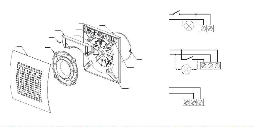
right) of relative humidity. The system is additionally equipped with a timer. The operation of the fan depends on the power supply connection method. If connected as
shown in Fig.4, the fan will start automatically when the air humidity level exceeds the set value of the humidity sensor. Next, the fan will switch o when the air
humidity level is reduced below the set value, plus the switch-o delay time set with the timer elapses. Switch-o delay time is regulated by the “CZAS/TIME”
potentiometer in the range of 3-30min (the minimum switch-o delay time is obtained by turning the potentiometer maximum to the left).
If connected as shown in Fig. 3, the fan can also be started with its standard light sensor or operating the separate on/o switch. Depending on the setting of the
“DELAY” slider on the controller, the fan will start operating when voltage is detected on the“SL” terminal or after 2 minutes after voltage is detected. After a signal loss
at the “SL” terminal due to switching o the light or the on/o switch, the air exhaust fan will stop after the stop delay time set with the potentiometer if the humidity
level in the room is below the level preset on the potentiometer. The humidity detection system is the master system.
NOTE: When the green diode located in the electronic system is on, it means that the humidity level in the room is higher than the preset on the potentiometer
controlling the humidity level adjustment. As long as the diode is on, the fan will not start counting down the stop delay after which the fan is switched off. It will
take place only after the humidity level in the room drops and the green diode goes off.
INSTALLATION
The fan shall only be installed, connected to electrical mains and commissioned
for use by qualified personnel in accordance with applicable laws!
Assembly
•
Precisely determine where the fan will be installed.
•Prepare the power cable. Use NYM-O 2x1.5 mm² (H07V-K 2x1.5 mm²) or NYM-O 3x1.5 mm² (H07V-K 3x1.5 mm²) with a maximum outside diameter of 8 mm,
depending on the version of the equipment.
NOTE: Before starting work, make sure that the power cord is not live.
•Measure and drill holes for the fan and ø6 mm mounting pins included with the product.
•Remove the front panel (1) and the rotor cover (2). The latches are released by turning them counterclockwise.
14
EN

•Remove the electric cover (4) xed with screws (3).
Applicable to the H version: A sensor is attached to the electric cover. Remove the cover carefully so as not to damage the wiring harness connecting the sensor to
the controller.
•Route the power cord in double insulation through the rubber grommet (10). Insert a sucient length of the cord so that the wires can be connected to the power
terminals.
Before mounting the fan: remove all foreign objects from its inside; check manually that the fan rotor moves freely; check that there is room for opening the
non-return valve baffle (9) located at the outlet of the bathroom extractor fan;
It is recommended to connect the fan to the duct using a flexible pipe connection!
•Place the fan housing (8) and the mounting pins in the previously drilled holes.
ATTENTION: The fan must be mounted so that the electrical compartment is at the top.
•Mount the fan to the substructure by driving the screws into mounting pins through the mounting holes (11).
•Remove the outer insulation from the power cord and remove the 4 mm of insulation from the wires.
•Arrange the power cord and connect according to the electrical wiring diagram applicable to the model installed.
Applicable to the T and H version: Insert the cores of the power cord into the corresponding holes of the terminal strip. For ease of use, lift the levers on the clamps.
•Verify the tightness of the cable cores in the terminals.
•Check if the fan is rmly installed and correctly wired.
Applicable to the T and H version: Set the stop delay time and the humidity sensor sensitivity level using the potentiometer knobs on the controller (7).
•Check the tightness of the power cord.
- The power cord must be secured so that in case of ooding there is no ingress of water to live parts.
•Place the electric cover (4) and secure with the screws (3).
•Slide the handles of the front panel (1) into the holes of the impeller cover (2).
•Place the front panel and the impeller cover on the front of the fan in a counterclockwise direction by approx. 5°. Then turn clockwise until the latches are locked.
ATTENTION! A rotating impeller can crush your fingers!
It is forbidden to start the fan without a protective mesh against touching the moving parts!
15
EN

First start
Start the air exhaust fan only with all safety precautions in place and all hazards eliminated. Check that it runs steadily and the air is handled eciently (out of the room
and through the air exhaust ductwork to the outside).
Check the operation of the fan (noise, vibration, the possibility to control the rotation speed).
Operate the air exhaust fan only with the front panel installed, as it is a direct touch guard on the suction side. Depending on the actual installation conditions, the fan
may require a protection against touching the moving parts on the delivery side. Suitable delivery-side direct guards can be provided on request. If the fan is guarded
against direct touch due to their installation conditions (e.g. in line with the air exhaust ductwork), no direct touch guard is required if the installation conditions
provide an equivalent level of safety. Note that the air exhaust fan user is liable for compliance with current safety standards and may be held liable for accidental injury
or death caused by failure to provide the required safety equipment.
Electrical connections
•
Electrical connections and commissioning of the fan shall only be completed by qualied professional electricians.
•Always follow the applicable standards, safety regulations and technical requirements specied by the power company!
•The power supply line for the axial fan requires a multi-pole circuit breaker / isolation switch with a minimum contact break gap of 3 mm (ref. EN 60335-1)!
•The mains system, voltage and frequency must match the nameplate ratings of the fan.
•Fans with the stop delay timer: the maximum voltage limit on terminal SL to initiate the stop delay time countdown or start the air exhaust fan is approx. 130 V AC.
Dimensions
The dimensions of specic fan models are shown in Fig. 5.
MAINTENANCE AND CLEANING
Servicing and maintenance
•Use protective footwear and gloves during maintenance!
•During all maintenance and servicing works the electrical and OHS regulations (IEC 60364-3) must be observed.
•Before servicing the fan, isolate it from the mains voltage with the circuit breaker. Secure the circuit breaker against inadvertent operation!
•The fan ductwork must be clear of foreign bodies: hazard of injury by objects blown out at a high speed!
16
EN

•Do not attempt any maintenance when the air exhaust fan is running or at live voltage!
•If excessive vibrations are felt or heard, have the technical inspection carried out by a qualied electrician.
•The maintenance intervals depend on the actual contamination of the fan rotor and must not be longer than 6 months!
•Check the fan rotor for cracks.
•The manufacturer shall not be liable for any damage resulting from unprofessional repairs.
•For equipment where engines with ball bearings have been used with“lifetime lubrication”, the engine does not require lubrication.
Cleaning
Electrocution hazard by damaged wiring insulation!
Before attempting to clean the fan, isolate it from the mains voltage with the circuit breaker.
Secure the circuit breaker against inadvertent operation!
•Clean the front panel and the visible parts of the housing with a damp cloth.
•Do not use aggressive paint solvents!
•Do not clean with a high pressure cleaner or strong jets of water!
•Clean carefully to prevent water from entering the motor or the terminal box.
•Always keep the guard grille at the suction side clean.
WARRANTY TERMS & CONDITIONS
1. Warranty period for the proper operation of the fan 7 years, from the date of sale.
2. The warranty rights and obligations will be void and null without demonstrating a proof of purchase (a receipt or an invoice).
3. The warranty covers all defects and damage attributable to the manufacturer.
4. Have your product delivered for warranty servicing to the manufacturer or the original seller.
5. The manufacturer undertakes to repair the product or replace it with a new counterpart within 14 days from ling your warranty complaint.
6. The warranty does not cover any of the following: damage to the product attributable to improper or unqualied installation, operation against the intended use,
improper transport, storage and/or maintenance, any faults attributable to unauthorized repairs, or any accidental damage.
17
EN

7. The warranty does not cover the installation or the maintenance of the product.
8. For all matters not provided for by this Warranty Certicate, the Polish Civil Code (Articles 577- 582) shall apply.
Do not dispose of waste electrical equipment with household waste.
The crossed-out wheelie bin symbol on this product means that it is waste of electrical and electronic equipment (WEEE) at the end of its operating life
and shall not be disposed with household waste. The crossed-out wheelie bin symbol species that the product is subject to obligatory waste
segregation schedules for proper disposal. The product is made from recyclable materials and components. The product user is required to return the
product which has become WEEE to a WEEE collection unit. The operators of WEEE collection units, including local WEEE locations, product resellers and
other WEEE collection locations managed by local authorities form a proper waste disposal system. Proper WEEE disposal helps avoid harmful eects to
humans and the environment from the risk caused by hazardous components this product may contain. The household plays an important role in
contributing to reuse and recovery, including recycling, of used up appliances, and it is the stage where attitudes are created that impact the
preservation of the common being the clean natural environment. Households are among the leading consumers of small appliances and equipment. A rational
management of operation and disposal of small appliances and equipment will contribute to ecient recycling.
18
EN

LN
N
L
L
N
N
L
SL
L
NSL
N
L
Rys. 2
Fig. 2
Изобр. 2
Obr. 2
Rys. 3
Fig. 3
Изобр. 3
Obr. 3
Rys. 4
Fig. 4
Изобр. 4
Obr. 4
12
3
4
8
7
6
5
10
11
9
Rys. 1
Fig. 1
Изобр. 1
Obr. 1
47

Producent / Manufacturer / Производитель / Výrobce / Výrobca:
AWENTA E.W.A. Chomka Spółka Jawna, 05-300 Mińsk Mazowiecki, Stojadła, ul. Warszawska 99, Poland
Tel: +48 25 758 52 52, + 48 25 758 93 92 fax: +48 25 758 14 62
INDEX / ИНДЕКС Ø1 Ø2 A B X Y W Z
WPA110 100 110 152 152 180 180 132 89
WPA125 120 125 152 152 180 180 132 89
Rys. 5
Fig. 5
Изобр. 5
Obr. 5
Ø1
Ø2
Y
X
Z
WA
B
48
This manual suits for next models
1
Table of contents
Other Awenta Fan manuals

Awenta
Awenta WA Series User manual

Awenta
Awenta Vega WGB100 User manual

Awenta
Awenta WKA150 Turbo User manual

Awenta
Awenta WA Series User manual

Awenta
Awenta SYSTEM + SILENT KWS 100 User manual

Awenta
Awenta WGB125 User manual

Awenta
Awenta WA150 User manual

Awenta
Awenta WXO User manual

Awenta
Awenta Escudo WES100H User manual

Awenta
Awenta AHR User manual

Awenta
Awenta LOOP WL125 User manual

Awenta
Awenta Orbit WXO100R User manual

Awenta
Awenta Escudo WEB100 User manual

Awenta
Awenta Escudo WEB150 User manual

Awenta
Awenta CVU User manual

Awenta
Awenta Veco WV100 User manual

Awenta
Awenta WKA 150 T User manual

Awenta
Awenta CM User manual

Awenta
Awenta WA User manual

Awenta
Awenta WL User manual