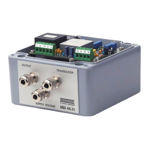
Messotron MBI 46.12 Series User manual

Version 2.1 en MBI 46.12 operating instructions.docx
Issue date: 08/2022 Page 1 of 32
Operating Instructions
Miniature CF Measuring Amplifier
Series MBI 46.12

Version 2.1 en MBI 46.12 operating instructions.docx
Issue date: 08/2022 Page 2 of 32

Version 2.1 en MBI 46.12 operating instructions.docx
Issue date: 08/2022 Page 3 of 32
Contents
1 Contents...............................................................................................4
1.1 Warranty and liability........................................................................4
1.2 Technical support and contact details...............................................4
2 Safety Instructions..............................................................................5
2.1 Intended use ....................................................................................5
2.2 Conditions at the installation site......................................................5
2.3 General hazards if the safety instructions are not followed...............5
2.4 Qualified personnel ..........................................................................5
2.5 Check for transport damage.............................................................6
3 Warning and Other Messages............................................................6
3.1 Use of warning messages................................................................6
3.2 Other messages...............................................................................7
4 Product Description............................................................................7
4.1 Glossary...........................................................................................7
4.2 Function and design.......................................................................10
4.3 Suitable displacement sensors.......................................................11
4.4 Overview of types and options........................................................14
5 Placing into Service ..........................................................................15
5.1 Pin assignment...............................................................................15
5.2 Setting options of the measuring amplifier......................................17
5.3 Adjustment using trimming potentiometer.......................................19
5.4 Basic configuration of measuring amplifier .....................................21
5.5 Optimizing the linearity characteristic of the measuring chain.........24
6 Operation ...........................................................................................28
7 Repairs...............................................................................................28
8 Maintenance.......................................................................................29
8.1 Preventative maintenance..............................................................29
8.2 Cleaning.........................................................................................29
9 Disposal .............................................................................................29
10 Declaration of EU-Conformity........................................................30
11 Technical Specifications................................................................31

Version 2.1 en MBI 46.12 operating instructions.docx
Issue date: 08/2022 Page 4 of 32
1 Contents
Read carefully before use!
Please read and always follow these operating instructions.
Retain for future reference!
Please retain these operating instructions in a safe location for future
reference.
Treat the identification plate on the device with care!
If the device has to be repaired or replacement parts are needed, you must
specify the model and the serial number. Both are indicated on the
identification plate.
Warnings and safety instructions
Observe the warnings and safety instructions in these operating
instructions to avoid physical injury and property damage.
1.1 Warranty and liability
Warranty and liability claims against MESSOTRON cannot be raised if
•damage occurs because the operating instructions are not followed or
•modifications have been made that are not documented in the operating
instructions.
1.2 Technical support and contact details
Please contact us if you have any questions. You can reach us at the
following contact address:
MESSOTRON Hennig GmbH & Co KG
Friedrich-Ebert-Str. 37
64342 Seeheim-Jugenheim, Germany
Phone: +49 (0) 6257 82331
Fax: +49 (0) 6257 85783
For further information please visit our webpage:
www.messotron.com/service.

Version 2.1 en MBI 46.12 operating instructions.docx
Issue date: 08/2022 Page 5 of 32
2 Safety Instructions
2.1 Intended use
The carrier frequency measuring amplifier MBI 46.12 (“the device”) must
only be used to operate inductive displacement sensors of the differential
transformer type (LVDTs) and differential inductors / half-bridge sensors
(LVITs) as well as the associated signal processing equipment. The device
must only be used with passive displacement sensors (i.e. sensors without
active embedded electronics). Any other use is considered improper use.
Observe the legal and safety regulations required for the respective
application. This also applies to the use of accessories.
In order to ensure proper and safe operation, the device must only be
operated according to the information provided in these operating
instructions.
2.2 Conditions at the installation site
Check the required conditions at the installation site (e.g. temperature and
weather conditions). The limits for the device are specified in chapter 11
“Technical Specifications”.
Have the device checked by MESSOTRON before putting it back into
service if foreign objects or liquids got inside the device.
Do not use the device near other devices, machines or equipment that
generate strong electric or magnetic fields.
2.3 General hazards if the safety instructions are not followed
The device is designed to the state of the art and is safe when used as
intended. However, if the device is used and operated improperly (e.g. by
insufficiently qualified personnel), residual hazards may arise.
2.4 Qualified personnel
The device must only be placed into service and operated by trained skilled
persons who are aware of the hazards involved. The skilled persons must
be familiar with the national occupational health and safety regulations,
accident prevention regulations as well as approved technical practices
and guidelines.

Version 2.1 en MBI 46.12 operating instructions.docx
Issue date: 08/2022 Page 6 of 32
2.5 Check for transport damage
Before unpacking, check the packaging of the device for damage. If the
packaging has been damaged during transport and there is reason to
believe that the device may be damaged, it must not be placed into service.
In this case, have the device checked by MESSOTRON before use.
3 Warning and Other Messages
3.1 Use of warning messages
The following hazard levels according to ANSI Z 535 are used for warning
messages:
Warning sign, signal word
Explanation
Indicates a hazardous situation, which, if
not avoided, will result in death or serious
injury.
Indicates a hazardous situation, which, if
not avoided, could result in death or
serious injury.
Indicates a hazardous situation, which, if
not avoided, could result in minor or
moderate injury.
Indicates a potential property damage: The
product could be damaged or the
environment could be harmed.
Warning messages affecting your personal safety are very clearly marked.
Always observe these warnings to avoid physical injury and property
damage.
A warning message (for either Danger, Warning or Caution) looks like this:
Cause and potential consequences
•How to avoid the hazard
WARNING
CAUTION
DANGER
NOTICE
WARNING

Version 2.1 en MBI 46.12 operating instructions.docx
Issue date: 08/2022 Page 7 of 32
3.2 Other messages
Notes contain important information for optimum use of the
device. Not observing a note may result in incorrect
measurements; however, this will usually not result in damage to
the device.
4 Product Description
4.1 Glossary
Term
Definition
Carrier
frequency
measuring
amplifier
Series MBI 46.12 CF measuring amplifiers are used in
inductive measuring chains
•to provide the inductive sensor with the required
excitation voltage,
•to amplify the sensor output signal and
•to convert the output signal into a normalized analog
voltage signal.
Types of displacement sensors
Displacement
sensor
In these instructions the term “displacement sensor”
often abbreviated to “sensor” is used. These devices are
also known as “transducers” or “position sensors”.
MESSOTRON differentiates the following three
displacement sensor types:
Differential
transformer
(LVDT)
Differential transformers consist of a primary coil and two
secondary coils placed around a movable magnetic core.
The coils are coupled based on the transformer principle.
The acronym LVDT stands for “Linear Variable
Differential Transformer”.
Inductive half-
bridge,
differential
inductor (LVIT)
Differential inductors represent a Wheatstone half-bridge
with two measuring coils. The impedance of the two
measuring coils is influenced in opposite directions by a
movable magnetic core.
They are also referred to as LVIT (Linear Variable
NOTE

Version 2.1 en MBI 46.12 operating instructions.docx
Issue date: 08/2022 Page 8 of 32
Term
Definition
Inductance Transducer).
Long-stroke
sensors based
on the eddy
current
principle
Long-stroke sensors are inductive displacement sensors
using a half-bridge circuit. Only one coil is used for
measuring. The second coil is designed as a space-
saving equivalent circuit. A movable measuring tube
(made of a conductive material) changes the impedance
of the measuring coil based on the eddy current
principle.
Construction
Symmetric
sensor
The measuring coil halves of differential transformers
and inductors are built in a symmetrically (mirrored)
design. The electrical zero is at the center of the nominal
stroke.
Asymmetric
sensor
The space-saving equivalent circuit of the 2nd coil of the
long-stroke sensors results in an asymmetric design
enabling a more favorable displacement-to-length ratio.
The electrical zero is at the start of the nominal stroke
(when the measuring tube completely covers the
measuring coil).
Immersion core
(core with core
rod)
The immersion core is a two-piece, rod-shaped part
consisting of
•a magnetic core and
•a core rod, i. e. a purely mechanical extension made
of a non-magnetic material.
Measuring tube
The measuring tube is made of aluminum. In asymmetric
displacement sensors it is moved over the measuring coil
drawing energy from the coil field proportional to the
tube’s position (eddy current effect).
Characteristic data
Excitation
voltage (Usp)
AC voltage (typically 1...5 Vpp), supplying the inductive
sensor.
Carrier or
bridge
frequency
Excitation frequency (usually 5 or 10 kHz) to drive the
inductive displacement sensor.

Version 2.1 en MBI 46.12 operating instructions.docx
Issue date: 08/2022 Page 9 of 32
Term
Definition
Measurement
voltage
Output signal proportional to the displacement (AC
voltage in the mV range) provided by the inductive
displacement sensor.
Zero point
At the electrical zero, the output signal of the
displacement sensor is zero. Refer to the data sheet of
the displacement sensor for physical position of the zero
point.
Rated output
The rated output of the sensor is defined as the ratio of
the sensor output voltage (measurement voltage) to the
sensor input voltage (excitation voltage) at the end of the
nominal stroke. For calibrated displacement sensors the
rated output is e.g. 80 mV/V, independent of the nominal
stroke of the displacement sensor.
In older displacement sensor data sheets, the term
“nominal output” is used.
Sensitivity
The sensitivity is defined as the ratio of the measurement
voltage to the excitation voltage per mm of displacement
(e.g. 10 mV/V/mm).
For standardization purposes information on sensitivity
and rated output for MESSOTRON displacement
sensors is determined and provided independent of
phase (i.e. without consideration of a phase shift).
Phase (phase
shift)
With inductive sensors and/or long connecting cables,
there will be a noticeable phase shift between the
excitation voltage and the measurement voltage. This
phase shift lowers the (effective) sensitivity of the sensor
in the measuring chain.
All MESSOTRON series MBI 46.12 measuring amplifiers
can compensate a phase shift.
Linearity error
The linearity error of measuring devices is the maximum
deviation between the nominal characteristic (straight
line) and the real characteristic of the measuring device.
The error information is referenced to the total measuring
range (FSO / Full Scale Output).
Signal output of the measuring amplifier

Version 2.1 en MBI 46.12 operating instructions.docx
Issue date: 08/2022 Page 10 of 32
Term
Definition
(Nominal)
output range
The (nominal) output range of the measuring amplifier
indicates the range covered by the output signal, if the
displacement sensor operates in the (nominal)
measuring range.
Voltage output
Analog voltage output of the measuring amplifier:
a) typically ±10 V for symmetric displacement sensors
b) typically 0...10 V for asymmetric displacement
sensors
4.2 Function and design
The MBI 46.12 generates the AC voltage (excitation voltage Usp) required
for operating inductive displacement sensors. The frequency (carrier
frequency) is typically 5 kHz (optionally 1...20 kHz).
The output signal proportional to the displacement (the measurement
voltage) returned by the displacement sensor is preamplified by the
measuring amplifier and evaluated ratiometrically, i.e. in relation to the
excitation voltage. This way measurement errors are avoided that result
from fluctuations of the excitation voltage, e.g. due to an impedance
change of the displacement sensor.
In subsequent stages, the measurement signal is filtered and scaled to the
desired output range for further processing.

Version 2.1 en MBI 46.12 operating instructions.docx
Issue date: 08/2022 Page 11 of 32
0
~
E
4
2
1
2
3
1
3
0
15 V
24 V
±10 V
0 ... 10 V
low
high
Oscillator
=
~
Filter
P
P
Ph
P
R
E
R
2
6
5
7
8
Option
UA0
UA
-
+
Figure 1 Block diagram with terminal assignment
PETrimmer potentiometer for gain adjustment
P0Trimmer potentiometer for zero adjustment
PPh Trimmer potentiometer for phase compensation
R2Resistor for setting the trim range for the zero point
REResistor for basic configuration of gain
4.3 Suitable displacement sensors
The MBI 46.12 CF measuring amplifier can be used with a variety of
inductive sensors. For details on the requirements, refer to the technical
specifications in chapter 11.
In particular check the following:
•Electrical design (type of displacement sensor),
•Required carrier frequency,
•Excitation voltage and
•Rated output / sensitivity.
NOTE

Version 2.1 en MBI 46.12 operating instructions.docx
Issue date: 08/2022 Page 12 of 32
The following chapters describe the electrical design of the three
displacement sensor types offered by MESSOTRON.
4.3.1 Linear Variable Inductance Transducers (LVITs)
Electrically displacement sensors based on the differential inductor
principle, also called LVITs, represent a Wheatstone half-bridge consisting
of two measuring coils. If the core moving inside the coils is in its mid-
position (electrical zero), both measuring coils will show the same
impedance. The bridge circuit is balanced. The measurement voltage is
zero.
Figure 2 Measuring amplifier with differential inductor
If the core is moved out of its mid-position, the impedances of the two
measuring coils change and the measurement voltage increases
proportionally with the displacement within the measuring range.
U
Out
A
Immersion-
core
°
°
°
U
Exc
0 V
A
B
A
B
Oscillator
Schematic circuit diagram
of CF amplifier
AMP
Filter
U
Meas
-s
0
+s
°
°
UA
UA0

Version 2.1 en MBI 46.12 operating instructions.docx
Issue date: 08/2022 Page 13 of 32
4.3.2 Linear Variable Differential Transformers (LVDT)
Differential transformers consist of a primary coil and two secondary coils
placed around an immersion core. The coils are coupled based on the
transformer principle.
AC voltage drives the primary coil inducing a voltage in the secondary coils.
When the immersion core is at its mid-position, this voltage is zero due to
the symmetrically wound secondary coils. If the immersion core is moved,
the measurement voltage changes proportionally to the displacement of the
core.
Figure 3 Measuring amplifier with differential transformer
4.3.3 Long-stroke sensor (eddy current principle)
Long-stroke sensors are displacement sensors using a half-bridge circuit.
Only one coil is used as the measuring coil. The second coil is designed as
a space-saving equivalent circuit. A movable measuring tube (made of a
conductive material) changes the impedance of the measuring coil based
on the eddy current principle. In contrast to symmetric displacement sen-
sors, the electrical zero of long-stroke sensors is at the start of the nominal
stroke (the measuring tube completely covering the measuring coil).
U
Out
U
Exc
U
Meas
-s
0
+s
Immersion
core
0 V
°
Oscillator
°
°
B
A
B
AMP
Filter
A
°
°
Schematic circuit diagram
of CF amplifier
°
UA
UA0

Version 2.1 en MBI 46.12 operating instructions.docx
Issue date: 08/2022 Page 14 of 32
Figure 4 Measuring amplifier with long-stroke sensor
4.4 Overview of types and options
The measuring amplifier is available in the following versions:
MBI 46.12/
x
y
/zzz
Power supply
Options
±15 VDC
1
5
/RS
with mounting bracket
+24 VDC
2
4
/0-10 V
Output signal 0...10 V
/nn kHz
Altern. carrier frequency in the range (1...20 kHz)
/ V6
with 6x-preamplifier for sensors with a rated
output < 130 mV/V
Oscillator
°
°
U
Out
0 V
°
U
Exc
U
Meas
0
+s
Measuring
tube
AMP
Filter
A
B
A
B
Schematic circuit diagram
of CF amplifier
UA
UA0

Version 2.1 en MBI 46.12 operating instructions.docx
Issue date: 08/2022 Page 15 of 32
5 Placing into Service
NOTICE
Only qualified skilled persons are allowed to place the measuring amplifier
into service.
Electrostatic discharge at electronic assemblies can damage the
components before they are placed into service. Therefore, take all
necessary measures to avoid electrostatic charging (ESD protective
measures).
Provided the sensor cable is routed professionally, the distance between
the displacement sensor and the measuring amplifier can be 100 m and
more.
Connect the inductive displacement sensor with the measuring
amplifier using a screened, low-capacitance cable.
Do not route the cable in parallel with power lines. In addition,
maintain a sufficient distance to electric drives, transformers and
frequency converters.
5.1 Pin assignment
NOTICE
The connections are not protected against reverse polarity.
If connections are reversed or if an incorrect external voltage is applied,
the device can be destroyed.
The displacement sensors must be connected to the measuring amplifier
according to the pin assignment specified in the table below. The power
supply, the output signal and the displacement sensor are connected using
connecting blocks. Therefore, no soldering is required for installation.
The conductor color code corresponds to IEC 60757:
NOTICE
NOTICE
NOTE
NOTE
NOTICE
BU –blue
RD –red
WH –white
BK –black
BN –brown
YE –yellow

Version 2.1 en MBI 46.12 operating instructions.docx
Issue date: 08/2022 Page 16 of 32
Terminal
Connection
Assignment
3
+15 VDC
24 V high
Supply voltage
1
- 15 VDC
24 V low1)
2
0 VDC
UA0
----
UA0 1)
reference potential supply
reference potential output
4
UA
Voltage output UA
5
S1
Excitation voltage +
7
S2
Excitation voltage –
6
M1
Amplifier input +
8
M2
reference potential of
displacement sensor (LVDTs)
Figure 5 Pin assignment of measuring amplifier
NOTICE
1) Please note: At the 24 V-version U A0 and 24 V low are at different
potential (difference approx. 12 V). Do not connect them!
If the displacement sensor is connected according to the table above, there
is a positive (increasing) output signal, when the core moves out of the
displacement sensor or the measuring tube moves downward from the
sensor housing. If a negative (decreasing) signal is desired for this direction
of movement, switch the connections terminal 5 and terminal 7.
Amplifier
Linear Variable
Differential
Transformers
all Dxx
Linear Variable
Inductance
Transducer
all Wxx except WP
Long-stroke
sensor e.g.
WP
Terminal
Wire
strand
Cable
Plug
Wire
strand
Cable
Plug
Cable
Plug
5
WH
(BN)
WH
2 (B)
BU
BU
3 (C)
BU
C
7
BU
BU
3 (C)
RD
RD
2 (B)
RD
B
6
BK
BK
4 (D)
WH+YE
WH
1 (A)
WH
A
8
RD
RD
1 (A)
-
-
-
-
-
Figure 6 Connection of MESSOTRON displacement sensors
NOTICE

Version 2.1 en MBI 46.12 operating instructions.docx
Issue date: 08/2022 Page 17 of 32
5.2 Setting options of the measuring amplifier
The measuring amplifier must be adapted to the displacement sensor
used. The following parameters must be set:
•Position of the electrical zero point,
•Phase compensation (possibly caused by the sensor type and the
connecting cable),
•Gain (adapt to sensor sensitivity).
At the factory, a basic configuration for all three parameters is set in the
measuring amplifier. This is achieved by using a variable component
assembly (resistors / capacitors) based on:
•a reference displacement sensor, if the sensor type is known,
•the sensor specification provided by the customer,
•the sensor that may have been ordered at MESSOTRON together with
the amplifier or
•a typical adjustment, if the sensor is unknown.
Some parameters of the basic configuration can be changed, if required
(see chapter 5.4 Basic configuration of measuring amplifier).
In any case, the measuring amplifier must be adjusted to the sensor used
on site using the trimming potentiometer (see chapter 5.3). The measuring
amplifier will be fine-tuned at the MESSOTRON factory, if a sensor is
ordered together with the measuring amplifier.
5.2.1 Position of the electrical zero point
-15
-10
-5
0
5
10
15
-20 -15 -10 -5 0 5 10 15 20
Displacement
Output voltage
Uout desired
Uout actual
c

Version 2.1 en MBI 46.12 operating instructions.docx
Issue date: 08/2022 Page 18 of 32
Figure 7 Correction of the zero point
The electric output signal of a real inductive displacement sensor is not
always exactly zero at the mechanical zeropoint (Dimension A for
MESSOTRON displacement sensors). Material and manufacturing
tolerances may cause small deviations, which can be compensated using
the zero-point potentiometer. Small tolerances in mechanical adjustments
of the displacement sensor can be compensated in the same way.
If the zero-point potentiometer is twisted, this will result in a vertical shift of
the characteristic curve for measured displacement to output signal.
5.2.2 Phase compensation
Due to the design principle, inductive displacement sensors can show a
phase shift between the excitation voltage and the measurement voltage.
The measuring amplifier evaluates the ratio of excitation voltage and
measuring voltage to suppress any measurement errors due to fluctuations
of the excitation voltage. If the phase shift is not compensated, the
sensitivity of the sensor can deviate.
Figure 8 Phase shift
Figure 8 shows that there is a reduced voltage ratio of UM1/USif there is no
phase compensation. Phase compensation results in an optimized voltage
ratio UM2/US.
-15
-10
-5
0
5
10
15
-20 -15 -10 -5 0 5 10 15 20
UA Soll
UA Ist
020 40 60 80 100 120 140 160 180 200 220 240 260 280 300 320 340 360
Voltage
Uexc.
Umeas.
US
UM2
UM1

Version 2.1 en MBI 46.12 operating instructions.docx
Issue date: 08/2022 Page 19 of 32
The phase compensation of the MBI 46.12 shifts the evaluation of the
measurement voltage on the time axis in such a way that the phase
position caused by the displacement sensor is compensated and the full
sensitivity of the displacement sensor can be used.
5.2.3 Gain
To obtain the desired output signal, the gain of the measuring amplifier
must be set depending on the rated output of the displacement sensor
used. If the output signal does not reach the desired value, e.g. at the end
of the nominal stroke, the gain must be increased.
-15
-10
-5
0
5
10
15
-20 -15 -10 -5 0 5 10 15 20
Displacement
Output voltage
Uout desired
Uout actual
Figure 9 Gain correction
A larger gain causes an increase in the gradient of the displacement-to-
output-signal characteristic curve (or a counter-clockwise rotation of the
characteristic curve).
5.3 Adjustment using trimming potentiometer
Make sure that the basic configuration of the measuring amplifier
is suitable for the displacement sensor used. If this is not the
case, change the basic configuration as described in chapter 5.4.
Using the trimming potentiometers, the measuring amplifier can be
adjusted to the displacement sensor within certain limits. Likewise, small
tolerances in adjustments of the displacement sensor can be compensated
in the same way.
NOTE

Version 2.1 en MBI 46.12 operating instructions.docx
Issue date: 08/2022 Page 20 of 32
The measuring amplifier will only show its nominal characteristics
after a warm-up time of approximately 15 minutes.
Figure 10 Location of trimming potentiometers
5.3.1 Adjustment for symmetric displacement sensors
With symmetric displacement sensors, the electrical zero is at the center of
the nominal stroke. Typically, the voltage output of the measuring amplifier
provides a symmetric output signal (-10 V...0 V...+10 V) for a symmetric
displacement sensor.
•To adjust the zero point, remove the core from the sensor housing and
set the output signal of the measuring amplifier to 0 V using the zero-
point potentiometer P0. Reinsert the core into the displacement sensor
and secure the core to retain the output signal. Small corrections are
permitted when using the zero-point potentiometer after the mechanical
adjustment
If you cannot set the zero point as described above, then alternatively
bring the core into the position where the displacement sensor provides
NOTE
Gain
potentiometer
Zero-point
potentiometer
Phase
potentiometer
Table of contents
Other Messotron Amplifier manuals

