Messotron MBI 46.31 Series User manual

Version 2.1 en MBI 46.31 operating instruction.docx
Issue date: 01/2022 Page 1 of 42
Operating Instructions
CF Measuring Amplifier
Series MBI 46.31
MBI 46.31
Eurocard PCB with
front panel
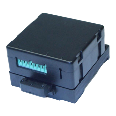
MBI 46.31
In field housing

Version 2.1 en MBI 46.31 operating instruction.docx
Issue date: 01/2022 Page 2 of 42
Contents
1 General.................................................................................................3
1.1 Warranty and liability ........................................................................3
1.2 Technical support and contact details...............................................3
2 Safety Instructions ..............................................................................4
2.1 Intended use.....................................................................................4
2.2 Conditions at the installation site ......................................................4
2.3 General hazards if the safety instructions are not followed...............4
2.4 Qualified personnel...........................................................................4
2.5 Check for transport damage.............................................................5
3 Warning and Other Messages ............................................................5
3.1 Use of warning messages ................................................................5
3.2 Other messages...............................................................................5
4 Product Description ............................................................................6
4.1 Glossary...........................................................................................6
4.2 Function and design .........................................................................9
4.3 Suitable displacement sensors.......................................................11
4.4 Overview of types and options........................................................14
5 Placing into Service...........................................................................18
5.1 Pin assignment...............................................................................18
5.2 Setting options of the measuring amplifier......................................20
5.3 Adjustment using trimming potentiometer.......................................23
5.4 Basic configuration of measuring amplifier .....................................26
5.5 Optimizing the linearity characteristic of the measuring chain.........32
5.6 Improving the noise rejection..........................................................35
6 Operation ...........................................................................................36
7 Repairs...............................................................................................36
8 Maintenance.......................................................................................37
8.1 Preventative maintenance..............................................................37
8.2 Cleaning.........................................................................................37
9 Disposal .............................................................................................37
10 EU Declaration of Conformity ........................................................38
Electronics with a supply voltage < 50 V ................................................38
Electronics with a supply voltage > 50 V ................................................39
11 Technical Specifications ................................................................40

Version 2.1 en MBI 46.31 operating instruction.docx
Issue date: 01/2022 Page 3 of 42
1 General
Read carefully before use!
Please read and always follow these operating instructions.
Retain for future reference!
Please retain these operating instructions in a safe location for future reference.
Treat the identification plate on the device with care!
If the device has to be repaired or replacement parts are needed, you must
specify the model and the serial number. Both are indicated on the identification
plate.
Warnings and safety instructions
Observe the warnings and safety instructions in these operating instructions to
avoid physical injury and property damage.
1.1 Warranty and liability
Warranty and liability claims against MESSOTRON cannot be raised if
•damage occurs because the operating instructions are not followed or
•modifications have been made that are not documented in the operating
instructions.
1.2 Technical support and contact details
Please contact us if you have any questions. You can reach us at the following
contact address:
MESSOTRON GmbH & Co KG
Friedrich-Ebert-Str. 37
64342 Seeheim-Jugenheim, Germany
Phone: +49 (0) 6257 999 730
For further information please visit our webpage: www.messotron.com.

Version 2.1 en MBI 46.31 operating instruction.docx
Issue date: 01/2022 Page 4 of 42
2 Safety Instructions
2.1 Intended use
The carrier frequency measuring amplifier MBI 46.31 (“the device”) must only
be used to operate inductive displacement sensors of the differential
transformer type (LVDTs) and differential inductors / half-bridge sensors (LVITs)
as well as the associated signal processing equipment. The device must only
be used with passive displacement sensors (i.e. sensors without active
embedded electronics). Any other use is considered improper use.
Observe the legal and safety regulations required for the respective application.
This also applies to the use of accessories.
In order to ensure proper and safe operation, the device must only be operated
according to the information provided in these operating instructions.
2.2 Conditions at the installation site
Check the required conditions at the installation site (e.g. temperature and
weather conditions). The limits for the device are specified in chapter 11
“Technical Specifications”.
Have the device checked by MESSOTRON before putting it back into service if
foreign objects or liquids got inside the device.
Do not use the device near other devices, machines or equipment that generate
strong electric or magnetic fields.
2.3 General hazards if the safety instructions are not followed
The device is designed to the state of the art and is safe when used as
intended. However, if the device is used and operated improperly (e.g. by
insufficiently qualified personnel), residual hazards may arise.
2.4 Qualified personnel
The device must only be placed into service and operated by trained skilled
persons who are aware of the hazards involved. The skilled persons must be
familiar with the national occupational health and safety regulations, accident
prevention regulations as well as approved technical practices and guidelines.

Version 2.1 en MBI 46.31 operating instruction.docx
Issue date: 01/2022 Page 5 of 42
2.5 Check for transport damage
Before unpacking, check the packaging of the device for damage. If the
packaging has been damaged during transport and there is reason to believe
that the device may be damaged, it must not be placed into service. In this
case, have the device checked by MESSOTRON before use.
3 Warning and Other Messages
3.1 Use of warning messages
The following hazard levels according to ANSI Z 535 are used for warning
messages:
Warning sign, signal word
Explanation
Indicates a hazardous situation, which, if not
avoided, will result in death or serious injury.
Indicates a hazardous situation, which, if not
avoided, could result in death or serious injury.
Indicates a hazardous situation, which, if not
avoided, could result in minor or moderate
injury.
Indicates a potential property damage: The
product could be damaged or the environment
could be harmed.
Warning messages affecting your personal safety are very clearly marked.
Always observe these warnings to avoid physical injury and property damage.
A warning message (for either Danger, Warning or Caution) looks like this:
Cause and potential consequences
•How to avoid the hazard
3.2 Other messages
Notes contain important information for optimum use of the device.
WARNING
CAUTION
DANGER
NOTICE
NOTE
WARNING

Version 2.1 en MBI 46.31 operating instruction.docx
Issue date: 01/2022 Page 6 of 42
Not observing a note may result in incorrect measurements; however,
this will usually not result in damage to the device.
4 Product Description
4.1 Glossary
Term
Definition
Carrier
frequency
measuring
amplifier
Series MBI 46.31 CF measuring amplifiers are used in
inductive measuring chains
•to provide the inductive sensor with the required excitation
voltage,
•to amplify the sensor output signal and
•to convert the output signal into a normalized analog
current or voltage signal.
Types of displacement sensors
Displacement
sensor
In this these instructions the term “displacement sensor” often
abbreviated to “sensor” is used. These devices are also
known as “transducers” or “position sensors”.
MESSOTRON differentiates the following three displacement
sensor types:
Differential
transformer
(LVDT)
Differential transformers consist of a primary coil and two
secondary coils placed around a movable magnetic core. The
coils are coupled based on the transformer principle.
The acronym LVDT stands for “Linear Variable Differential
Transformer”.
Inductive half-
bridge,
differential
inductor (LVIT)
Differential inductors represent a Wheatstone half-bridge with
two measuring coils. The impedance of the two measuring
coils is influenced in opposite directions by a movable
magnetic core.
They are also referred to as LVIT (Linear Variable Inductance
Transducer).
Long-stroke
sensors based
on the eddy
Long-stroke sensors are inductive displacement sensors
using a half-bridge circuit. Only one coil is used for
measuring. The second coil is designed as a space-saving

Version 2.1 en MBI 46.31 operating instruction.docx
Issue date: 01/2022 Page 7 of 42
Term
Definition
current
principle
equivalent circuit. A movable measuring tube (made of a
conductive material) changes the impedance of the
measuring coil based on the eddy current principle.
Construction
Symmetric
sensor
The measuring coil halves of differential transformers and
inductors are built in a symmetrically (mirrored) design. The
electrical zero is at the center of the nominal stroke.
Asymmetric
sensor
The space-saving equivalent circuit of the 2nd coil of the long-
stroke sensors results in an asymmetric design enabling a
more favorable displacement-to-length ratio. The electrical
zero is at the start of the nominal stroke (when the measuring
tube completely covers the measuring coil).
Immersion core
(core with core
rod)
The immersion core is a two-piece, rod-shaped part
consisting of
•a magnetic core and
•a core rod, i.e. a purely mechanical extension made of a
non-magnetic material.
Measuring tube
The measuring tube is made of aluminum. In asymmetric
displacement sensors it is moved over the measuring coil
drawing energy from the coil field proportional to the tube’s
position (eddy current effect).
Characteristic data
Excitation
voltage (Usp)
AC voltage (typically 1...5 Vpp), supplying the inductive
sensor.
Carrier or
bridge
frequency
Excitation frequency (usually 5 or 10 kHz) to drive the
inductive displacement sensor.

Version 2.1 en MBI 46.31 operating instruction.docx
Issue date: 01/2022 Page 8 of 42
Measurement
voltage
Output signal proportional to the displacement (AC voltage in
the mV range) provided by the inductive displacement sensor.
Zero point
At the electrical zero, the output signal of the displacement
sensor is zero. Refer to the data sheet of the displacement
sensor for physical position of the zero point.
Rated output
The rated output of the sensor is defined as the ratio of the
sensor output voltage (measurement voltage) to the sensor
input voltage (excitation voltage) at the end of the nominal
stroke. For calibrated displacement sensors the rated output is
e.g. 80 mV/V, independent of the nominal stroke of the
displacement sensor.
In older displacement sensor data sheets, the term “nominal
output” is used.
Sensitivity
The sensitivity is defined as the ratio of the measurement
voltage to the excitation voltage per mm of displacement (e.g.
10 mV/V/mm).
For standardization purposes information on sensitivity and
rated output for MESSOTRON displacement sensors is
determined and provided independent of phase (i.e. without
consideration of a phase shift).
Phase (phase
shift)
With inductive sensors and/or long connecting cables, there
will be a noticeable phase shift between the excitation voltage
and the measurement voltage. This phase shift lowers the
(effective) sensitivity of the sensor in the measuring chain.
All MESSOTRON series MBI 46.3x measuring amplifiers can
compensate a phase shift.
Linearity error
The linearity error of measuring devices is the maximum
deviation between the nominal characteristic (straight line) and
the real characteristic of the measuring device. The error
information is referenced to the total measuring range (FSO /
Full Scale Output).

Version 2.1 en MBI 46.31 operating instruction.docx
Issue date: 01/2022 Page 9 of 42
Signal output of the measuring amplifier
(Nominal)
output range
The (nominal) output range of the measuring amplifier
indicates the range covered by the output signal, if the
displacement sensor operates in the (nominal) measuring
range.
Current output
Analog current output of the measuring amplifier:
typically 4...20 mA for the nominal stroke
Voltage output
Analog voltage output of the measuring amplifier:
a) typically ±10 V for symmetric displacement sensors
b) typically 0...10 V for asymmetric displacement sensors
4.2 Function and design
The MBI 46.31 generates the AC voltage (excitation voltage Usp) required for
operating inductive displacement sensors. The frequency (carrier frequency) is
typically 5 kHz (optionally 1...20 kHz).
The output signal proportional to the displacement (the measurement voltage)
returned by the displacement sensor is preamplified by the measuring amplifier
and evaluated ratiometrically, i.e. in relation to the excitation voltage. This way
measurement errors are avoided that result from fluctuations of the excitation
voltage, e.g. due to an impedance change of the displacement sensor.
In subsequent stages, the measurement signal is filtered and scaled to the
desired output range for further processing.

Version 2.1 en MBI 46.31 operating instruction.docx
Issue date: 01/2022 Page 10 of 42
0
~
C
J
J
2
1
2
C
X6
C
1
E
5
4
1
2
3
6
11
8
9
0
+
-
15 V
24 V
230 V~
DC
DC
DC
AC
±10 V
0 ... 10 V
4 ... 20 mA
Option
high
low
Oscillator
=
~
Filter
P
P
Ph
P
R
E
R
2
4
R
6
13
16
15
14
12
U
I
MBI 46.10
Option
Option
R
7
°
°
°
12
0 V
Figure 1 Block diagram with terminal assignment
PETrimmer potentiometer for gain adjustment
P0Trimmer potentiometer for zero adjustment
PPh Trimmer potentiometer for phase compensation
R2Resistor for setting the trim range for the zero point
R6/R7Resistors for zero offset
REResistor for basic configuration of gain
C1/C2Capacitors for phase compensation
C4Capacitor for adjustment of the cut-off frequency
J1/J2Plug contact to switch on the preamplifier in case of low output signal of
the displacement sensor; (position J1: with 6x preamplification; position J2:
no preamplification)

Version 2.1 en MBI 46.31 operating instruction.docx
Issue date: 01/2022 Page 11 of 42
4.3 Suitable displacement sensors
The MBI 46.31 CF measuring amplifier can be used with a variety of inductive
sensors. For details on the requirements, refer to the technical specifications in
chapter 11.
In particular check the following:
•Electrical design (type of displacement sensor),
•Required carrier frequency,
•Excitation voltage and
•Rated output / sensitivity.
The following chapters describe the electrical design of the three displacement
sensor types offered by MESSOTRON.
4.3.1 Linear Variable Inductance Transducers (LVITs)
Electrically displacement sensors based on the differential inductor principle,
also called LVITs, represent a Wheatstone half-bridge consisting of two
measuring coils. If the core moving inside the coils is in its mid-position
(electrical zero), both measuring coils will show the same impedance. The
bridge circuit is balanced. The measurement voltage is zero.
Figure 2 Measuring amplifier with differential inductor
NOTE
U
Out
A
Immersion-
core
°
°
°
°
U
Exc
0 V
A
B
A
B
Oscillator
Schematic circuit diagram
of CF amplifier
AMP
Filter
U
Meas
-s
0
+s
°
°

Version 2.1 en MBI 46.31 operating instruction.docx
Issue date: 01/2022 Page 12 of 42
If the core is moved out of its mid-position, the impedances of the two
measuring coils change and the measurement voltage increases proportionally
with the displacement within the measuring range.
4.3.2 Linear Variable Differential Transformers (LVDTs)
Differential transformers consist of a primary coil and two secondary coils
placed around an immersion core. The coils are coupled based on the
transformer principle.
AC voltage drives the primary coil inducing a voltage in the secondary coils.
When the immersion core is at its mid-position, this voltage is zero due to the
symmetrically wound secondary coils. If the immersion core is moved, the
measurement voltage changes proportionally to the displacement of the core.
Figure 3 Measuring amplifier with differential transformer
U
Out
U
Exc
U
Meas
-s
0
+s
Immersion
core
0 V
°
Oscillator
°
°
B
A
B
AMP
Filter
A
°
°
Schematic circuit diagram
of CF amplifier

Version 2.1 en MBI 46.31 operating instruction.docx
Issue date: 01/2022 Page 13 of 42
4.3.3 Long-stroke sensor (eddy current principle)
Long-stroke sensors are displacement sensors using a half-bridge circuit. Only
one coil is used as the measuring coil. The second coil is designed as a space-
saving equivalent circuit. A movable measuring tube (made of a conductive
material) changes the impedance of the measuring coil based on the eddy
current principle. In contrast to symmetric displacement sensors, the electrical
zero of long-stroke sensors is at the start of the nominal stroke (the measuring
tube completely covering the measuring coil).
Figure 4 Measuring amplifier with long-stroke sensor
Oscillator
°
°
U
Out
0 V
°
°
U
Exc
U
Meas
0
+s
Measuring
tube
AMP
Filter
A
B
A
B
Schematic circuit diagram
of CF amplifier

Version 2.1 en MBI 46.31 operating instruction.docx
Issue date: 01/2022 Page 14 of 42
4.4 Overview of types and options
MBI 46.31.
x
y
/zzz
Power
supply
Version and output signal
Options
±15 VDC
1
1
Eurocard PCB without front panel,
±10 V output; connector
/nn kHz –alter-
native CF in the
range 1...20 kHz
230 VAC
2
2
Eurocard PCB without front panel,
4 ... 20 mA output; connector
/0-10 V 1) output
signal 0...10 V
+24 VDC
3
3
Eurocard PCB with front panel,
±10 V output; connector
/0-20mA output
signal 0...20 mA
4
Eurocard PCB with front panel, 4
... 20 mA output; connector
5
Eurocard PCB without front panel,
±10 V output; terminal block
6
Eurocard PCB without front panel,
4 ... 20 mA output; terminal block
7
Field enclosure, ±10 V output
8
Field enclosure, 4 ... 20 mA
output
1) Option for symmetric displacement sensors (instead of ±10 V)
Eurocard PCB
Field enclosure
Field enclosure
with front panel
±15 V and +24 V
230 V
Figure 5 Available versions of measuring amplifier MBI 46.31

Version 2.1 en MBI 46.31 operating instruction.docx
Issue date: 01/2022 Page 15 of 42
4.4.1 Eurocard PCB
R2
R6
R7
J1
J2
C2
C1
Pph
P0
PE
U
I
1
16
15
14
13
MBI 46.10
0 V
+ 15 V
-15 V
Ia(Option)
Ua
24 V high
not
used
24 V low
0 V
Option
2
3
4
5
6
7
8
9
10
11
12
Displace-
ment
sensor
Weight app. 0,1 kg
167
100
C4
RE
Figure 6 Enclosure dimensions and position of components for Eurocard
PCBs
CF measuring amplifiers in the Eurocard PCB format are intended for mounting
into subracks (3 U) or other suitable housings. When installing the measuring
amplifiers, make sure there is sufficient distance between the amplifiers and
electrically conductive parts. Depending on the version, the Eurocard PCBs are
connected using a 32-pin type C connector to DIN 41612 or screw-type
terminals. The potentiometers for adjustment of the measuring amplifier are
located on the opposite side (front side).
4.4.2 Field enclosure
The aluminum enclosure can be mounted using 4x M6 screws. To mount the
enclosure, the cover must be removed.
The measuring amplifiers in the aluminum enclosure are IP65 (DIN EN 60529)
ingress-protection rated for protection against dust and water spray.

Version 2.1 en MBI 46.31 operating instruction.docx
Issue date: 01/2022 Page 16 of 42
All unused cable passages must be closed using suitable sealing plugs for
protection against moisture and dirt.
Connections for power supply, output signal and displacement sensors are
routed to the outside using three M12 cable glands (maximum cable diameter
6.5 mm). The cables are connected to terminal blocks (for pin assignment, see
chapter 5.1). The cable shield is not connected at the measuring amplifier. If
required, connect the cable shield at the other cable end.
Field enclosure with ±15 VDC and +24 VDC supply
1
2
3
4
) Current output
120
82
122
106
) at ±15 V
) at 24 V
) Voltage output
Ø6,4
16
15
14
13
1
R
2
R
R
R
6
7
E
4
C
J
1
J
C
C
1
2
2
Ph
P
P
P
0
E
MBI 46.10
DC
DC
U
I
11
6
2
3
4
2)
2)
1)
3)
5
4)
4)
Displacement
sensor
0 V
UEhigh
UElow
I
U
a
a
Weight app. 1,4 kg
Figure 7 Enclosure dimensions and position of components for ±15 VDC
and +24 VDC supply
NOTICE

Version 2.1 en MBI 46.31 operating instruction.docx
Issue date: 01/2022 Page 17 of 42
Field enclosure with 230 VAC supply
120
82
220
204
R
2
R
R
R
6
7
E
J
1
J
C
C
1
2
Pph
P0
PE
U
I
1
16
15
14
13
MBI 46.10
a
0 V
+ 15 V
-15 V
I(Option)
Ua
0 V
2
Option
2
3
4
5
6
7
8
9
10
11
12
Displace
ment
sensor
Weight app. 2 kg
not
used
4
C
Figure 8 Enclosure dimensions and position of components for 230 VAC
supply.
The power supply unit is located on a separate power supply board, mounted to
the back of the main board.
Figure 9 Power supply unit for 230 VAC supply
17
18
19
22
23
24
-15 V
+15 V
Ground GND
PE conductor
230 VAC
230 VAC

Version 2.1 en MBI 46.31 operating instruction.docx
Issue date: 01/2022 Page 18 of 42
5 Placing into Service
NOTICE
Only qualified skilled persons are allowed to place the measuring amplifier
into service.
Electrostatic discharge at electronic assemblies can damage the
components before they are placed into service. Therefore, take all
necessary measures to avoid electrostatic charging (ESD protective
measures).
Provided the sensor cable is routed professionally, the distance between the
displacement sensor and the measuring amplifier can be 100 m and more.
Connect the inductive displacement sensor with the measuring
amplifier using a screened, low-capacitance cable.
Do not route the cable in parallel with power lines. In addition,
maintain a sufficient distance to electric drives, transformers and
frequency converters.
5.1 Pin assignment
NOTICE
Note that the pin assignment is different depending on the type of
measuring amplifier.
The connections are not protected against reverse polarity.
If connections are reversed or if an incorrect external voltage is applied,
the device can be destroyed.
The displacement sensors must be connected to the measuring amplifier
according to the pin assignment specified in the table below. The supply voltage
(V), the output signal (A) and the displacement sensor (W) are connected by
cable for field enclosures and by connecting blocks or plug-in connections for
Eurocard PCBs. Therefore, no soldering is required for installation.
NOTICE
NOTICE
NOTICE
NOTE
NOTE

Version 2.1 en MBI 46.31 operating instruction.docx
Issue date: 01/2022 Page 19 of 42
Hazardous voltages inside the measuring amplifier with 230 V supply
voltage (type 46.31.2x).
Touching live parts can result in death, serious injury or considerable property
damage.
•Before opening the field enclosure, check all conductors. They must be de-
energized.
Connector
Terminal
block
Wire color (field
enclosure)
Assignment
W
V
A
ac 2
16
WH
Excitation voltage +
ac 4
15
BU
Excitation voltage –
ac 6
14
RD
Amplifier input –(measuring
signal –)
ac 8
13
BK
Amplifier input + (measuring
signal +)
ac 10
12
0 V
ac 12
11
BK
Supply voltage 24 V, low
ac 14
10
not used
ac 16
9
not used
ac 18
8
not used
ac 20
7
not used
ac 22
6
RD
Supply voltage 24 V, high
ac 24
5
RD
Voltage output
ac 26
4
BU
Current output
ac 28
3
(BU)
Supply voltage –15 V
ac 30
2
(RD)
Supply voltage +15 V
ac 32
1
(BK)
BK
0 V
Figure 10 Pin assignment of measuring amplifier
If the displacement sensor is connected according to the table above, there is a
positive (increasing) output signal, when the core moves out of the
displacement sensor or the measuring tube moves downward from the sensor
housing. If a negative (decreasing) signal is desired for this direction of
movement, switch the connections ac 2 (terminal 16) and ac 4 (terminal 15).
WARNING

Version 2.1 en MBI 46.31 operating instruction.docx
Issue date: 01/2022 Page 20 of 42
Terminal
Assignment
17
PE conductor
18
230 VAC
19
230 VAC
22
-15 V
23
+15 V
24
Ground GND
Figure 11 Pin assignment of 230 V power supply
Amplifier
Linear Variable
Differential
Transformers
all Dxx
Linear Variable
Inductance
Transducer
all Wxx except WP
Long-stroke
sensor e.g.
WP
Plug
Terminal
Wire
strand
Cable
Plug
Wire
strand
Cable
Plug
Cable
Plug
ac 2
16
WH
(BN)
WH
2 (B)
BU
BU
3 (C)
BU
C
ac 4
15
BU
BU
3 (C)
RD
RD
2 (B)
RD
B
ac 6
14
RD
RD
1 (A)
-
-
-
-
-
ac 8
13
BK
BK
4 (D)
WH+YE
WH
1 (A)
WH
A
Figure 12 Connection of MESSOTRON displacement sensors
5.2 Setting options of the measuring amplifier
The measuring amplifier must be adapted to the (displacement) sensor used.
The following parameters must be set:
•Position of the electrical zero point,
•Phase compensation (possibly caused by the sensor type and the
connecting cable),
•Gain (compensation of sensor sensitivity).
At the factory, a basic configuration for all three parameters is set in the
measuring amplifier. This is achieved by using a variable component assembly
(resistors / capacitors) based on:
•a reference displacement sensor, if the sensor type is known,
•the sensor specification provided by the customer,
Table of contents
Other Messotron Amplifier manuals
