Mestra 100249 User manual

Rev. 27/09/2019
VACUUM PORCELAIN FURNACE
Ref. 100249

2
Vacuum porcelain furnace EN
Thank you for having purchased the vacuum porcelain
furnace Ref. 100249. This manual provides a help for
the operation of the furnace. Please, read this manual
carefully before installation and use.
1. Unpack
We take many packing measures to ensure the security
of the furnace during transportation. If you have any
questions when you use our furnace, please contact your
dealer or manufacturer immediately.
1.1.Unpacking
Remove the packing belt and carton.
Remove the plastic bag outside the furnace.
Take out the outside foam.
Take out the firing platform and firing plate which
are placed in the upper foam.
Take out furnace from foam base carefully. Place it
on the stability of the desktop.
Take the vacuum pump out of the carton. Place it on
the ground nearby the furnace.
Recommend keeping the original packaging for
future transportation purposes.
1.2.Checking
Please check whether the model and quantity of
accessories accord with the list and whether the
appearance of the furnace is in good condition.
1.3.Accessories
Vacuum Pump: 1 set;
Platform: 1 PCS;
Firing Tray: 2PCS;
Silicon Tube: 1 PCS;
Support Pin: 1 Bag;
Fuse (15A): 1 PCS;
Fuse (5A): 1 PCS;
2. 2. Technical specifications
Dimensions:................ 320 x 392 x 426 mm (W x D x H)
Weight: .....................................................24 kg (furnace)
.......................................................................8 kg (pump)
Max. temperature:.................................................1200 ℃
Max. working vacuum:.........................................–98 kPa
Power supply: .................................... 220 V ±10 %, 15 A
Power consumption: ................................ 1.5 kVA ±10 %
3. Structure
3.1. Front view of furnace unit
1. Furnace shell
2. Crucible
3. Firing plate
4. Firing platform
5. Sealing ring
6. Metal tray
7. Working table
8. Touch screen
9. Power indicator
3.2.Rear view of furnace unit
1. Cooling shell
2. Vacuum pump electrical outlet
3. Fuse of vacuum pump
4. Vacuum hose connector
5. Fuse of power supply
6. Power switch
7. Power wire

3
4. Installation
4.1. Take out furnace from foam base carefully. Place it
on the stability of the desktop.
4.2. Take the vacuum pump out of the carton and place
it on the ground nearby the furnace. The position of
vacuum pump should be lower about 80 cm than
furnace.
1. Solenoid valve
2. Filter
3. Vacuum hose
4. Capacitor
5. Vacuum pump
6. Exhaust hole
4.3. Connect the vacuum pump hose to the vacuum hose
connector at the rear of the furnace.
4.4. Plug the vacuum pump power cord into the
electrical outlet at the rear of the furnace.
4.5. This furnace should be connected to a grounded
220 V, 15 A power socket.
4.6. Press power switch ON. The furnace will enter the
stand-by mode.
4.7. Press UP key to lift the muffle. Place the firing
platform on the middle of the tray.
NOTE:After switch on the furnace, the firing
platform must be placed on the tray. Otherwise
the sealing ring (O-ring) on the tray will be
burnout. The firing platform can’t be taken out
from the furnace except for long-distance
transportation.
4.8. The moisture in the muffle should be removed
correctly, otherwise the moisture may enter the
vacuum system to damage the vacuum pump and
solenoid valve etc. The service life of the furnace
may be shortened and even the furnace may be
damaged.
4.9. In order to prevent the accumulation of moisture in
the muffle, the new furnace should be operated
strictly according to following steps before using.
Switch on the furnace.
Select cleaning program “CLEAN”.
Press “START” key to run the program.
After the program completes, repeat above steps
at least ten times to dry the muffle completely so
that remove moisture in the muffle.
If the furnace is not used for a long period of
time, the user had better operate according to
above steps.
When the water level in the filter of vacuum pump
approaches 1/3 height, please unscrew the bolt at
the bottom of the filter immediately to drain off
water. Prevent water vapor from entering and
damaging the vacuum pump.
5. Operating instructions
Function description
The standby menu shows every function icon: Program,
Clean, Curve, Alarm, Configuration, Time, User Login.
NOTE: After switching on the furnace, please
operating it only when the tray is opened completely.

4
5.1.Firing type
5.1.1. This furnace has two firing types:
(1) Program number P1-P40: you can edit parameters
by yourself.
(2) Program number P41-P47: special programs for
Blue porcelain block.
- Choose the Program number in Standby Menu to
enter the program parameter menu.
5.1.2. Click program icon to enter firing standby menu.
5.1.3. In firing standby menu, the following functional
icons can be used:
UP and Down icons: click these icons to open
or close the tray door.
Return: click this icon to return the Standby
menu.
Run: click this icon to start the program.
Click every parameter to revise the value.
Click program number icon to enter the
selecting program menu and parameters setting
menu.
5.1.4. In firing standby menu, if pressing Run icon,
confirmation question will appear. If pressing Yes
icon, the selected program will start running. The
screen is showed program running menu.
5.1.5.
If you want to set the vacuum, please click
vacuum value icon to set directly.
If you don’t need the vacuum, please click
vacuum value icon to set “0” directly.
5.1.6. During firing program running, the firing curve,
firing time countdown and real vacuum value
inside the furnace will be showed on the firing
menu.
5.1.7. During firing program running, click Curveicon
to enter program running curve menu. The real-
time program running curve is showed.
5.1.8. During firing program running, if the furnace has
problem, the red icon is flashed. Click Alarm icon
to check the detailed alarm information.

5
5.2.Program
This furnace has 47 firing programs.
5.2.1. Program number P1-P40 are for normal
porcelain powder materials. These all 40
programs can be edited by yourself.
5.2.2. Program number P41-P47 are for Blue Porcelain
Block material.P41-P45 can’t be edited. Use
P46-P47 for editing your own programs.
5.2.3. In standby menu, you can click program number
icon to choose the program number by the
numeric keypad.
If you choose program 41, 42… 47, selection
menu of blue porcelain block will be showed on
the screen.
5.2.4. After choosing the suitable program, in standby
menu, click every parameter icon to set and
modify the related values by numeric keypad.
Parameter in standby menu (P1-P40) for
normal materials.
1. Idle temperature
2. Firing temperature
3. Dry time
4. Preheat time
5. Heat rate
6. Firing time
7. Cooling time
8. Vacuum starting temperature
9. Vacuum releasing temperature
10. Real-time vacuum value
11. Vacuum time
Parameter in standby menu (P41-P47) for blue
porcelain block.
1. Idle temperature
2. Firing temperature (part 1)
3. Firing temperature (part 2)
4. Preheat time
5. Heat rate (part 1)
6. Firing time (part 1)
7. Heat rate (part 2)
8. Firing time (part 2)
9. Cooling time
10. Cooling temperature
11. Vacuum starting temperature (part 1)
12. Vacuum releasing temperature (part 1)
13. Vacuum starting temperature (part 2)
14. Vacuum releasing temperature (part 2)
The parameters of programs P41-P45 can’t be
revised by yourself.

6
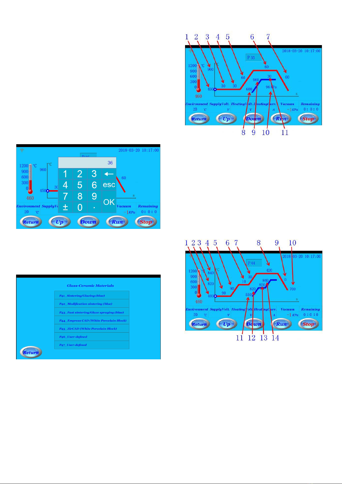
Parameters can be set within following values range:
Idle temperature: 350 ~ 750 ℃
Firing temperature: 500 ~ 1150 ℃
Times: 0 ~ 3600 seconds
Heat rate: 2 ~ 120 ℃/minute
Vacuum value: 0 ~ 99 kPa
Vacuum starting temperature: 400 ~ 960 ℃
Vacuum releasing temperature: 600 ~ 1200 ℃
When setting every firing parameter, please note
following important points:
Firing temperature should be greater than idle
temperature.
If cooling time is less than 60 seconds, the tray will
be opened after 60 seconds.
Vacuum releasing temperature should be greater than
Vacuum starting temperature.
Vacuum starting temperature should be greater than
Idle temperature.
Vacuum releasing temperature should be less than
Firing temperature.
Vacuum time should be less than firing time.
When you need to hold vacuum, please be sure to set
the vacuum value in parameter menu.
If vacuum time is set to 0:
-When temperature in the chamber is reached to
vacuum starting temperature, the vacuum pump
will be started.
-When temperature in the chamber is reached to
vacuum releasing temperature, the vacuum in the
chamber will be released.
If vacuum time is not set to 0, the vacuum pump will
be started only when temperature is rising and after
tray is closed; the vacuum in the chamber will be
released after vacuum time is completed.
5.3.Purge
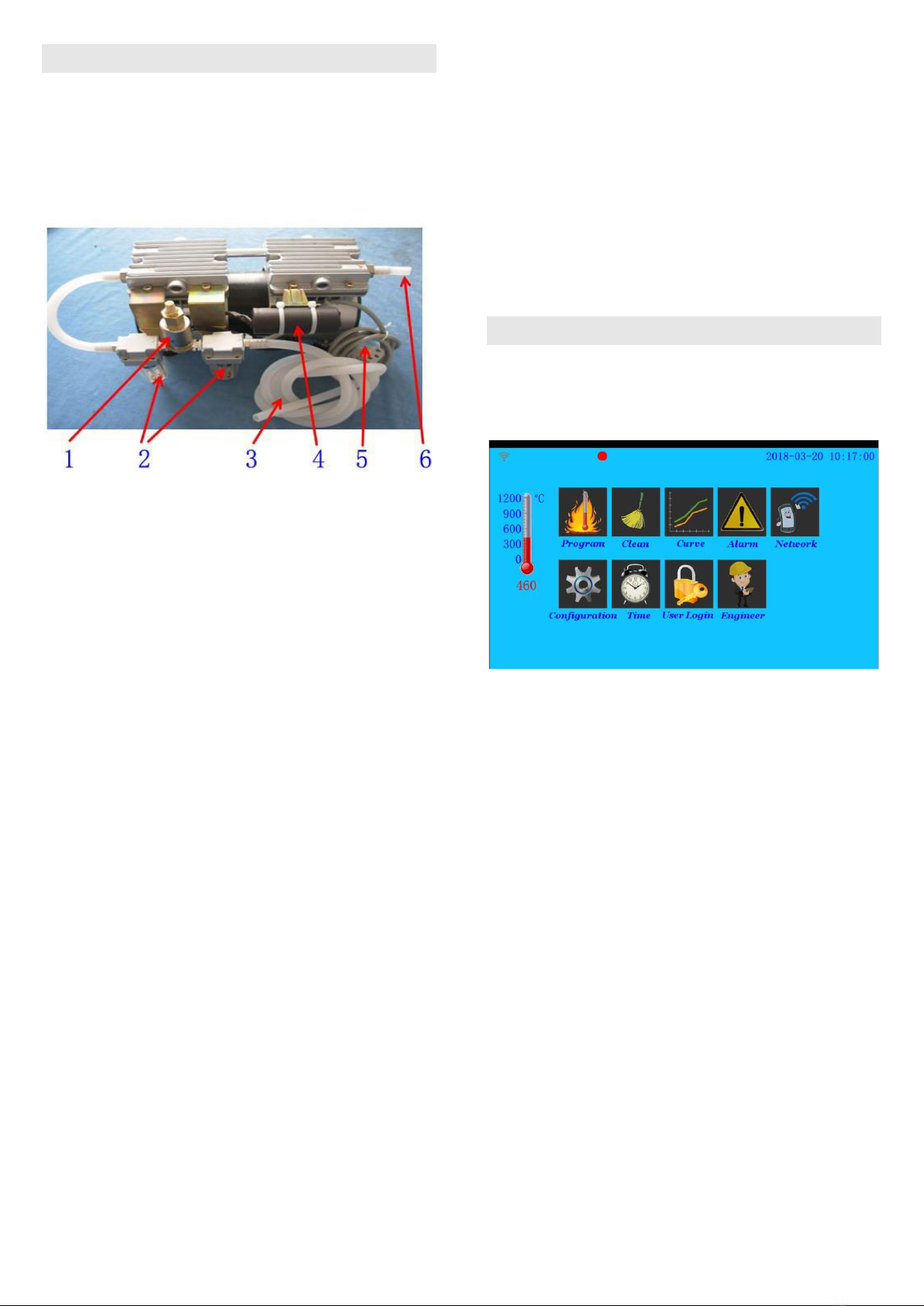
In standby menu, click Clean icon to enter clean menu.
If the muffle is moistened, contaminated or not used for
a long time, the clean function is recommended. This
clean function can also be used for testing vacuum
pump.
Click Run icon, the clean program will be started to
run. The temperature will reach to 960 ℃, and then
firing time will hold 300 seconds. During clean
program running, the vacuum pump will start to work
after tray is closed. The vacuum will be released in
the last 30 seconds of firing time.
NOTE:before vacuum is released, if vacuum in the
chamber is lowed to the limit, vacuum pump will
start to work again.
5.4.Program running curve
In standby menu, click Curve icon to enter program
running curve menu.
In program running curve, you may see the latest
temperature process curve.
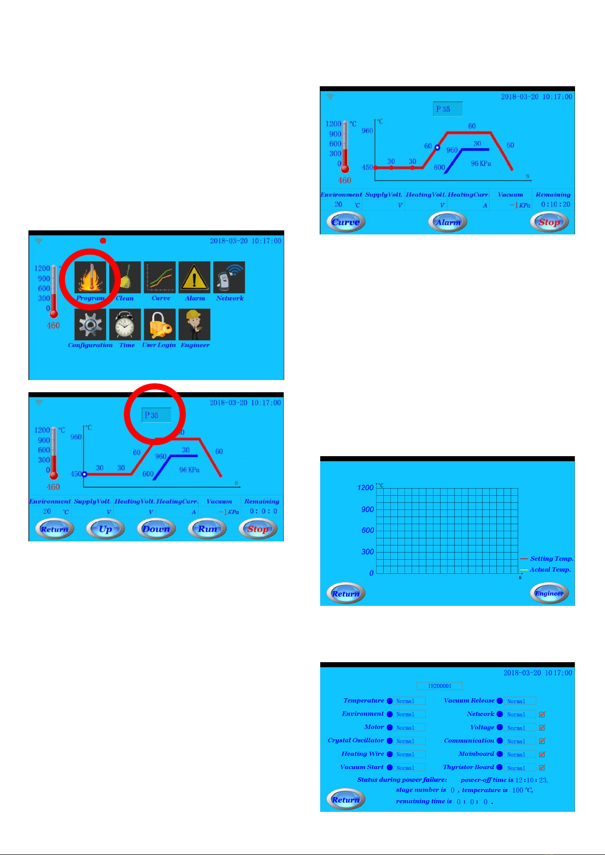
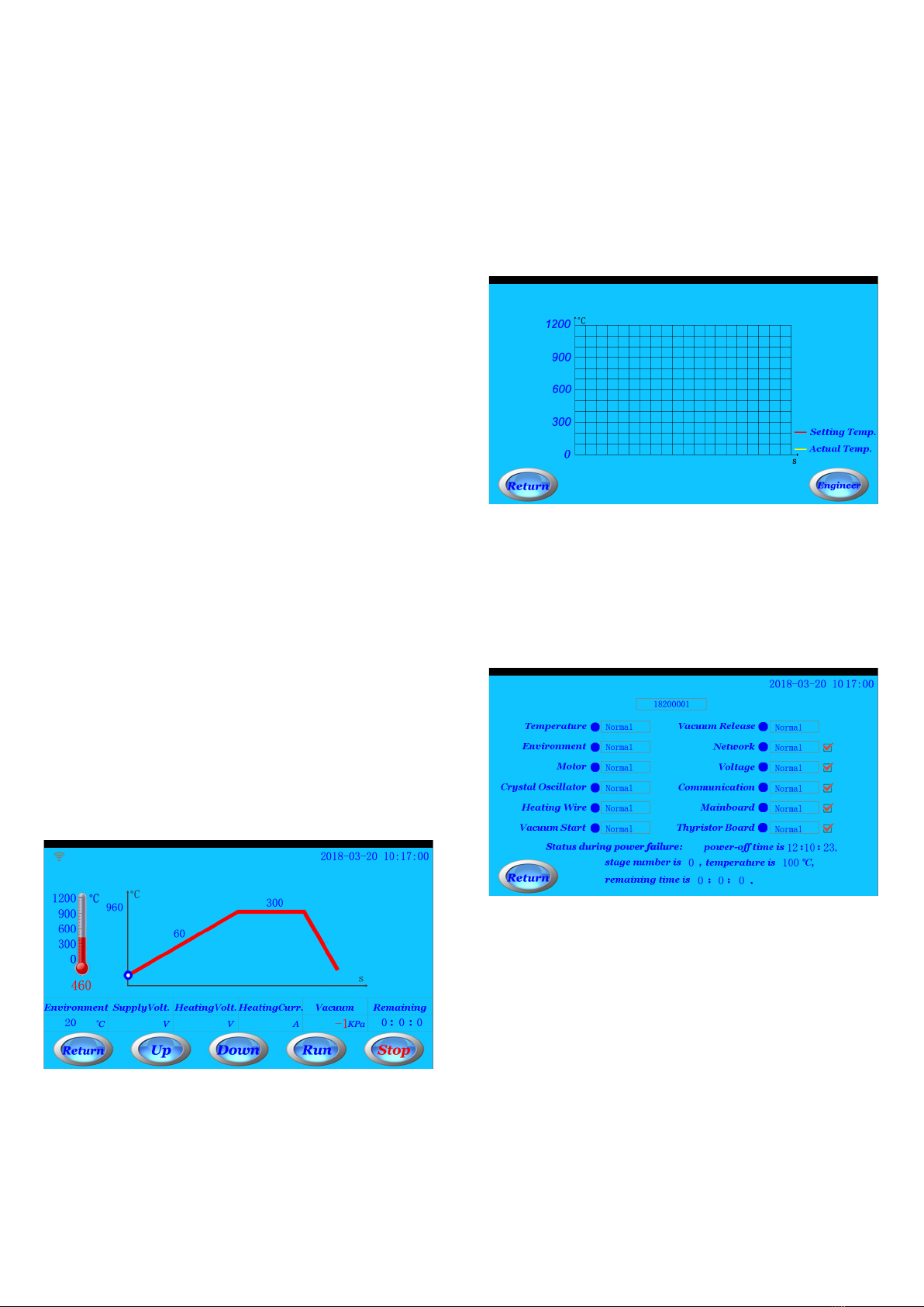
5.5.Alarm information
In standby menu, click Alarm icon to enter alarm
information menu.
When furnace has the trouble in standby status, a red
round icon will be flashed. The detailed alarm
information can be checked in alarm information
menu.
When the program is running, if power is failure, you
can see the status of program running in this alarm
menu when power is continued.
In alarm information menu, the upper part of screen
shows the serial number of this furnace; the bottom
parts show the furnace’s status in a recent of power
failure;
Five types of alarm information can set to cancel
reminder (including network alarm, voltage alarm,
communication alarm, mainboard alarm, thyristor
board alarm). When one or all of them are canceled
reminder, the relevant alarm information will not be
showed.

7
5.6.Parameter configuration
In standby menu, click Configuration icon to enter
parameter configuration menu.
5.6.1. Temperature calibration: when there is some
temperature deviation between actual temperature
and showed values on screen, you may adjust it by
temperature calibration menu.
Example 1: when temperature showed on screen
is higher 10 ℃than actual temperature, that is,
actual temperature is lower than values on screen,
please set temperature calibration to “+10”.
Example 2: when temperature showed on screen
is lower 10 ℃than actual temperature, that is,
actual temperature is higher than values on screen,
please set temperature calibration to “–10”.
The temperature calibration can set between
0 and 80 ℃.
5.6.2. Screen brightness: adjust brightness value from 1
to 63.
5.7.User login
In standby menu, click User login icon to enter user
login menu.
In user login menu, you may enter the password to
get the corresponding permission. You may also get
the information current user like level of permission
for current user, number of times used under current
permission, total number of times etc.
1. Number of uses under current level.
2. Current level.
3. Total number of uses under current level.
4. Total number of uses for this furnace.
5.8.Time settings
In standby menu, click Time setting icon to enter time
settings menu. You may modify system time in this
menu. You can also revise system time by clicking time
in the top right corner.
6. Temperature calibration
If the chamber temperature is too higher or too lower
during using furnace, the chamber temperature can be
calibrated by Silver Calibration Cup.
NOTE: before operating temperature calibration, the
chamber should be dried completely, otherwise
it will cause the incorrect temperature
calibration.
Please refer to follow steps to calibrate the muffle
temperature:
STEP 1: Cut off a silver sample (2–3 mm) and put it in
the calibration cup. Then place the calibration
cup in the middle of firing plate.
NOTE: the length of silver sample should not
be too longer, otherwise it will affect the
judgment about muffle temperature.
STEP 2: Select a self-defined program (P39) and set the
parameters as follows:
Dry time = 0
Preheat time = 0
Idle temperature = 600
Heat rate = 60
Firing temperature = 955
Firing time = 180
Cooling time = 0
Vacuum = 0
After setting all parameters, please start to
run this program.
When the program is finished, the silver
sample should not be melted.
If the silver sample is melted, it shows the
chamber temperature is still higher. Please
enter the temperature calibration menu to
decrease the chamber temperature.
After calibrating temperature, please
continue to operate SETP 1 and STEP 2
until the silver sample is not melted.
If the silver sample is not melted, please
continue to operate following calibration
procedure STEP 3 and STEP 4:

8
STEP 3: Cut off a silver sample (2–3mm) and put it in
the calibration cup. Then place the calibration
cup in the middle of firing plate;
NOTE: the length of silver sample should not
be too longer, otherwise it will affect the
judgment about muffle temperature.
STEP 4: Select a self-defined program P40 and set the
parameters as follows:
Dry time = 0
Preheat time = 0
Idle temperature = 600
Heat rate = 60
Firing temperature = 965
Firing time = 180
Cooling time = 0
Vacuum = 0
After setting all parameters, please start to
run this program.
When the program is finished, please
carefully check the silver sample:
If silver sample is melted into a round ball,
it shows that chamber temperature is
calibrated accurately.
If only the middle part of silver sample is
bulged or only a part of silver sample is
melted, which shows the chamber
temperature is still lower. Please enter the
temperature calibration menu to increase
the chamber temperature.
After calibrating temperature, please
continue to operate STEP 3 and STEP 4
until the silver sample is melted to a round
ball.
1. Original shape of silver sample before temperature
calibration.
2. Only the middle part of silver sample is bulged or
only a part of silver sample is melted.
3. Silver sample is melted to a round ball.
7. Vacuum conversion table
inHg kPa mmHg inHg kPa mmHg
1
4
20
16
53
400
2
7
50
17
57
430
3
10
70
18
60
450
4
13
100
19
64
480
5
17
120
20
68
510
6
21
150
21
71
530
7
24
170
22
74
560
8
27
200
23
78
580
9
30
220
24
81
610
10
34
250
25
85
630
11
37
270
26
88
660
12
40
300
27
91
680
13
43
320
28
94
710
14
47
350
29
98
740
15
50
370
30
101
760
1 inHg = 3.38 kPa = 25.4 mmHg
1 MPa = 1000 kPa = 1000000 Pa

9
8. Program information
Program
number
Preheat
temp.
Firint
temp.
Dry
time
Preheat
time
Firing
time
Cooling
time
Heat
rate Vacuum Vacuum
time
Vacuum
starting
temp.
Vacuum
release
temp.
Unit ºC ºC Second Second Second Second ºC/min kPa Second ºC ºC
Other P1-P11 450 960 120 120 180 0 60 0 150 600 960
Ivoclar
common
porcelain
powder
material
P12 450 980 0 0 90 60 80 95 0 500 980
P13 450 950 120 120 90 240 60 95 0 500 950
P14 450 930 180 180 90 240 60 95 0 500 930
P15 450 900 180 180 90 240 55 95 0 500 900
P16 450 900 180 180 90 240 60 0 0 500 900
P17 450 890 120 120 90 240 60 95 0 500 890
Ivoclar
zirconia
porcelain
powder
material
P18 4501000 200 200 900 300 100 0 0 500 1000
P19 450 910 180 180 90 240 55 95 0 500 910
P20 450 910 180 180 90 240 60 0 0 500 910
P21 450 900 120 120 90 240 55 95 0 500 900
VITA
common
porcelain
powder
material
P22 450 980 0 0 90 60 60 95 0 500 980
P23 450 950 120 120 90 240 60 95 0 500 950
P24 450 930 180 180 90 240 60 95 0 500 930
P25 450 930 180 180 90 240 55 95 0 500 930
P26 450 930 120 120 90 240 60 0 0 500 930
P27 450 920 120 120 90 240 60 95 0 500 920
VITA
zirconia
porcelain
powder
material
P28 450 1000 150 150 900 240 100 0 0 500 1000
P29 450 980 180 180 60 240 80 95 0 500 980
P30 450 930 180 180 60 240 55 95 0 500 930
P31 450 900 120 120 60 240 80 0 0 500 900
P32 450 760 120 120 60 240 60 95 0 500 760
Noritake
porcelain
powder
material
P33 450 980 0 0 60 90 70 95 0 500 980
P34 450 950 120 120 90 240 60 95 0 500 950
P35 450 930 180 180 90 240 60 95 0 500 930
P36 450 910 180 180 90 240 45 95 0 500 910
P37 450 910 180 180 90 240 60 0 0 500 910
P38 450 900 120 120 90 240 60 95 0 500 900
Calibration
temp.
P39 600 955 0 0 180 0 60 0 0 600 955
P40 600 965 0 0 180 0 60 0 0 600 955

Porcelain powder
material Program number Program name
Other porcelain powder
material P1-P11 User-defined
Ivoclar common porcelain
powder material
P12 Oxidation treatment for metal
P13 Powdery opaque layer (W)
P14 Powdery opaque layer (O)
P15 Dentin
P16 Glazing
P17 Modification
Ivoclar zirconia porcelain
powder material
P18 Heat treatment
P19 Dentin
P20 Glazing
P21 Modification
VITA common porcelain
powder material
P22 Oxidation treatment for metal
P23 Powdery opaque layer (W)
P24 Powdery opaque layer (O)
P25 Dentin
P26 Glazing
P27 Modification
VITA zirconia porcelain powder
material
P28 Heat treatment
P29 Welding effect
P30 Dentin
P31 Glazing
P32 Modification
P33 Metal oxidation treatment
Noritake porcelain powder
material
P34 Powdery opaque layer (W)
P35 Powdery opaque layer (O)
P36 Dentin
P37 Glazing
P38 Modification
Calibration temp. P39 Low temp.
P40 High temp.

11
Glass-Ceramics material
Program number P41 P42 P43 P44 P45 P46 P47
Modificable No No No No No Yes Yes
Preheat temp. 403 403 403 403 403 403 403
Dry time 360 360 90 360 360 360 360
Heat rate 1 90 90 90 90 90 90 90
Firing temp. 1 820 820 820 830 830 820 820
Firing time 1 10 10 10 10 10 10 10
Heat rate 2 30 30 30 30 30 30 30
Firing temp. 2 840 840 840 850 870 840 840
Firing time 2 420 180 420 180 180 420 420
Vacuum starting temp. 1 550 550 550 450 450 550 550
Vacuum release temp. 1 820 820 820 830 830 820 820
Vacuum starting temp. 2 820 820 820 830 830 820 820
Vacuum release temp. 2 840 840 840 849 869 840 840
Cooling temp. 700 700 700 710 870 700 700
Cooling time 0 0 0 0 0 0 0
Program number Program name
P41 Blue porcelain block: Sintering / Glazing
P42 Blue porcelain block: Modification sintering
P43 Blue porcelain block: Fast sintering / Glaze spraying
P44 White porcelain block: empress CAD
P45 White porcelain block: ZirCAD
P46 User_defined
P47 User_defined

12
Table of contents
Popular Furnace manuals by other brands

Drolet
Drolet TUNDRA II Installation and operating instructions

Lennox
Lennox SL280UHVX Series Unit information

Ferroli
Ferroli DOMItech C 24 Instructions for use, installation and maintenance

Carrier
Carrier FURNACE 58MVC owner's manual

Carrier
Carrier 58MVP040-14 Installation, start-up, and operating instructions

Bryant
Bryant 915SA Product data

Bentone
Bentone ST 133 K10K CN Installation and maintenance instruction

Maytag
Maytag Amana MEC96 Series installation instructions

Whip Mix
Whip Mix SinterPro Operator's manual

Allied
Allied 95G1UHEX Series Service manual

Trane
Trane THV1M087A936SA Service facts

VERDER
VERDER CARBOLITE GERO RWF 12/5 Installation, operation and maintenance instructions