4
INSTALLATION THROUGH FLAT
CEILING(S)
1. From the appliance manufacturer’s instructions,
determine the correct ue diameter for the chimney,
and proper location of the chimney.
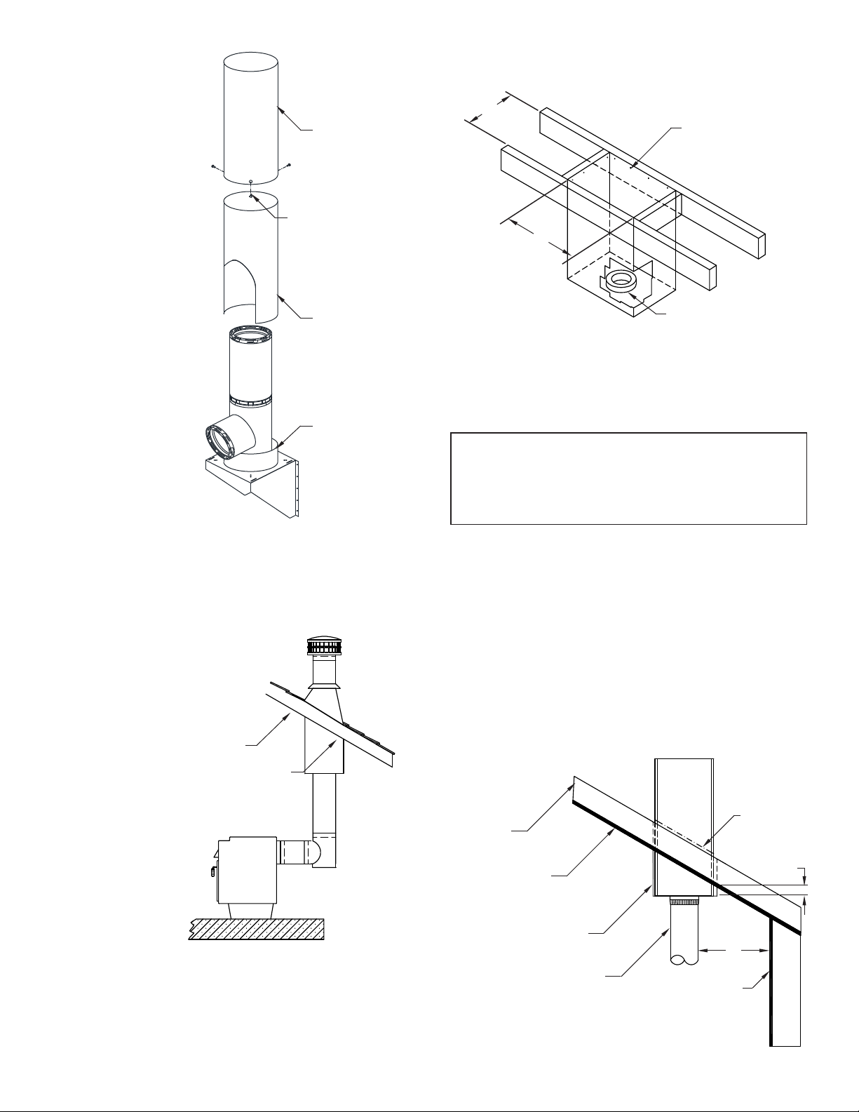
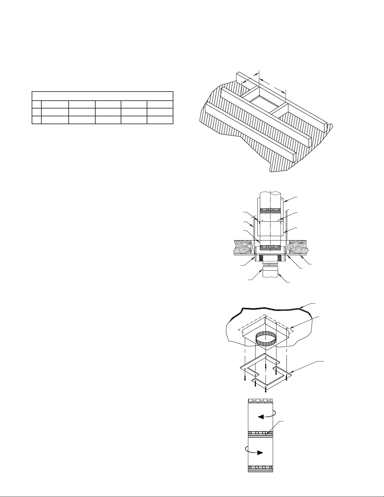
2. Using framing lumber equal to ceiling joist size, frame
ceiling opening as shown in FIG. 2 and TABLE 1.
TABLE 1
CHIMNEY FLUE DIAMETER
6” 7” 8” 10” 12”
A12-7/16” 13-7/16” 14-7/16” 17” 19”
B12-7/16” 13-7/16” 14-7/16” 17” 19”
NOTE: If possible, it is recommended that the chimney be located
in such a manner as to not cut the ceiling joist. The chimney can
be centered between joists on 16 inch centers in these areas.
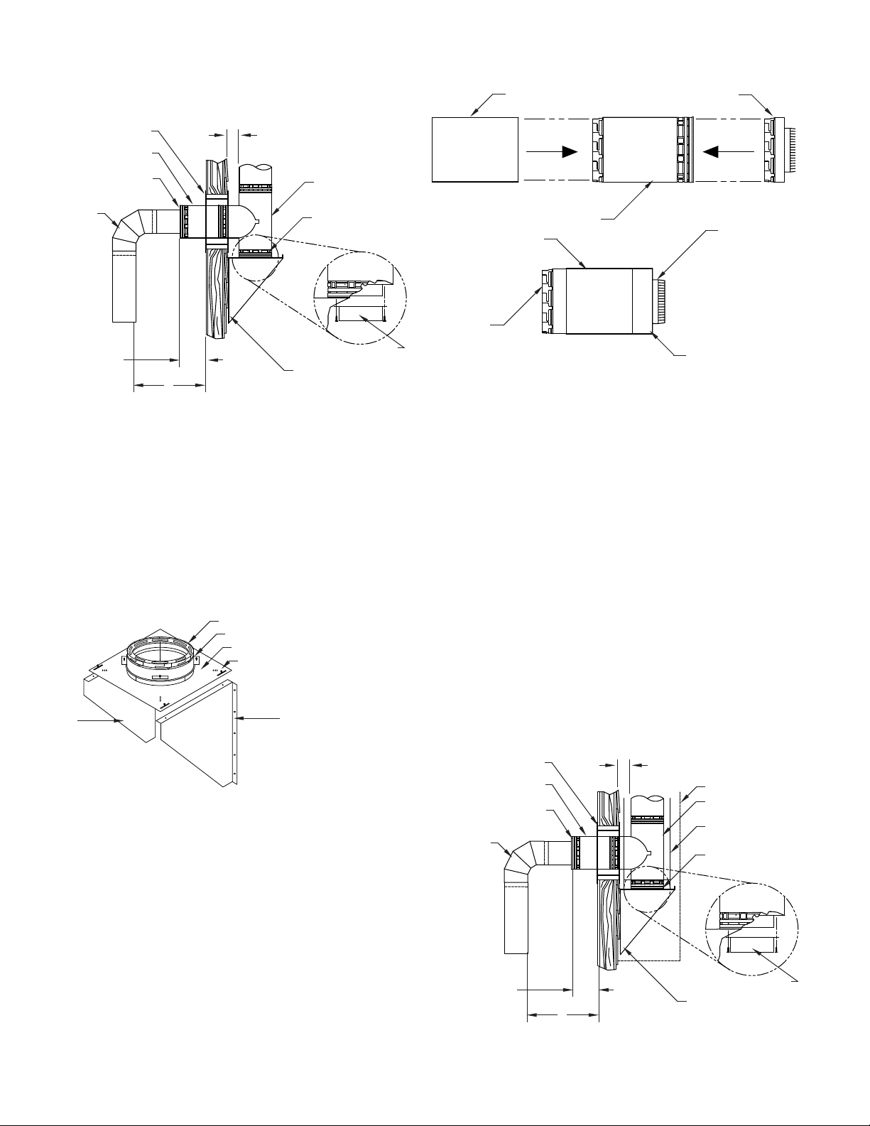
3. As shown in FIG. 3, insert the Ceiling Support
(TGCSP) from below until the anged edges are
rmly against the ceiling drywall. Secure into framing
with eight (8) 8-penny nails inserted through the sides
of the ceiling support. If the TGCSP was installed
during construction and drywall now covers the
anged edges, install Metal-Fab’s ceiling support trim
kit (TGCST), as shown in FIG. 4.
4. If the chimney is an enclosed installation for a wood stove or
coal burning appliance the clearance shields must be
installed (TGICS-C & TGOCS-C). Begin by installing a
TGICS-C around the Temp/Guard chimney and resting
on the Temp/Guard Ceiling Support (See FIG. 3).
The TGICS-C will center itself by the brackets attached
to the shields. Continue installing the shields around
the chimney for the full enclosed height. The
clearance shields are telescoping components and
will alternate between the inside clearance shield
(TGICS-C) and outside clearance shield (TGOCS-C).
The (TGICS-C and TGOCS-C) will be held together
by (3) self tapping screws supplied with the shields.
For offsets and tees use shields TGICS15L-C,
TGICS30L-C and TGICST-C.
5. Single wall or double wall connector pipe may now be
installed between the appliance and the ceiling support.
(See FIG 3.)
If the area above the ceiling is an attic, go to step 7.
6. Proceed to the next ceiling. If Metal-Fab Elbows are to
be used because the chimney is to be offset, refer to
“Installation of Elbows” section. Directly above the
Center of the ue in the ceiling support, mark the ceiling. A
plumb bob is normally used to nd the center. Cut an
opening in the ceiling using FIG. 2 and Table 1.
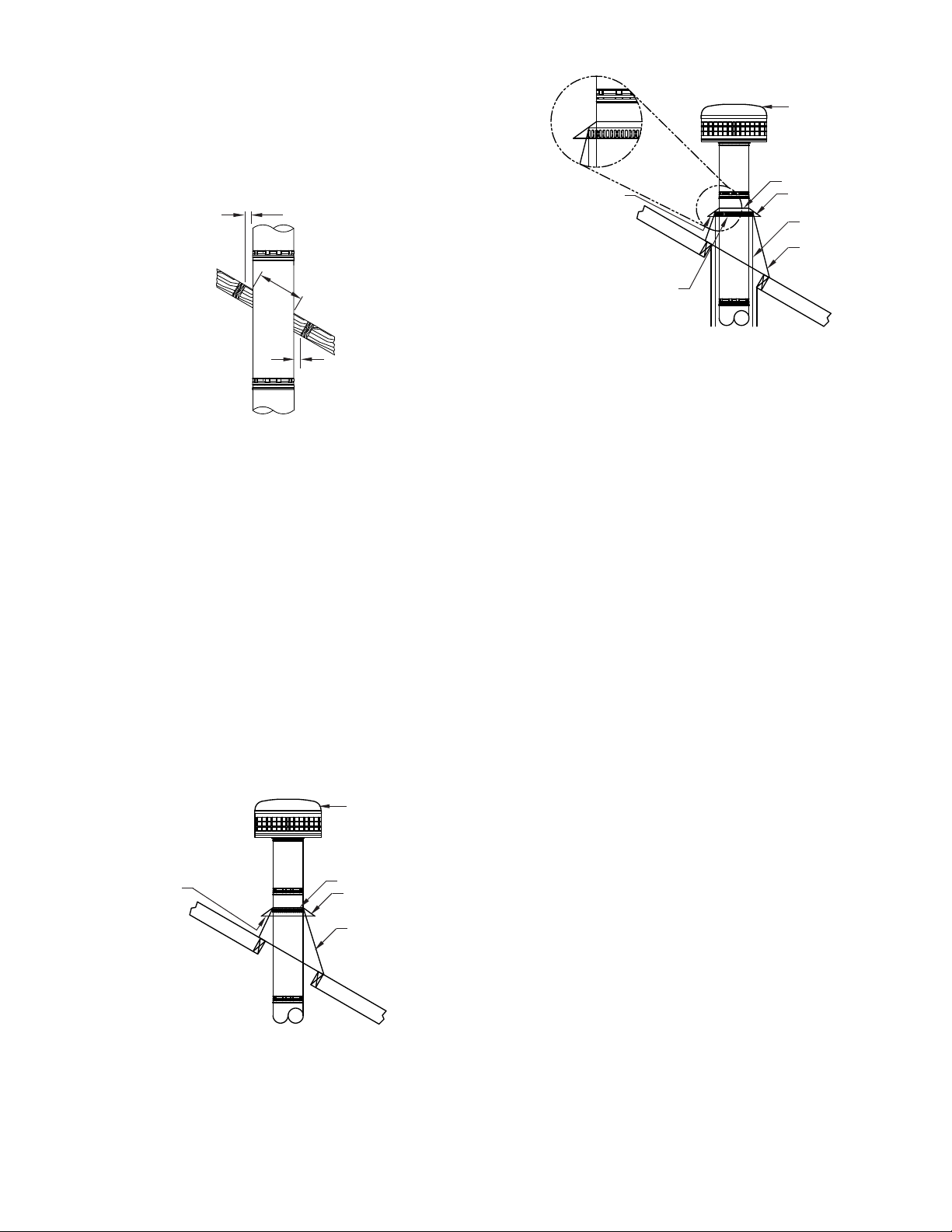
7. Install Temp/Guard chimney sections starting at the
TGCSP. Secure the sections by pushing together
and twisting until stop-locked (See FIG. 5).
Additional chimney sections may be added
to maximum height of 60 feet. At each additional
ceiling, a restop (TGFSA for Unenclosed
Installation) (TGFSA-C, For enclosed Installation
using Clearance Shields) is required. Insert the
TGFSA/TGFSA-C into the joist area prepared in step
5. Continue this process for each oor level until the
area above the attic.
B
A
FIG. 2
Framing lumber of
equal size to the joist should be used.
CEILING
DRYWALL
FLANGE
COVERED
BY DRYWALL
CEILING
SUPPORT TRIM
(TGCST)
FIG. 4
TWIST LOCK JOINT
FIG. 5
FIG. 3
CLEARANCE SHIELD
(TGOS)
CEILING DRYWALL
FLANGED EDGE
SINGLE OR
DOUBLE WALL
CONNECTOR PIPE
ATTACH TO
TGCSP WITH
SCREWS
CEILING
SUPPORT
(TGCSP)
CLEARANCE SHIELD
(TGICS)
SECURED WITH SELF
TAPPING SCREWS
(PROVIDED)
SPACER CLIPS
ENCLOSURE
TEMP/GUARD
CHIMNEY
NOTE: When the chimney extends between oors, which
can be occupied, the chimney must be enclosed to prevent
contact. As previously noted, 2” clearance to combustibles
for 6” - 12” diameters is to be maintained, except within the
joist area controlled by the TGCSP.