Metalware Interlok User manual

Metal
that works
Industrial shelving solutions since 1954
2020 Installation Guide – Interlok
Strength • Support • Integrity
*A minimum of two persons is recommended to carry out the assembly
2020-07

MELWARE
NOTICE
Use caution when handling and assembling metal parts. The metal may have sharp edges or corners. The use of
protective gloves is recommended. Do not use this unit for anything that is outside the designed function of
storage. Do not store loose or heavy items on the top shelves or on the top of the unit, for they create a falling
hazard that can injure yourself or others. Always remember to use proper lifting techniques when moving either
the boxed or assembled unit. Shelving should be periodically inspected for loose bolts, for damaged “T” uprights or
shelves, for proper seating of shelf and clip. Check loading to assure it is not being overloaded. If any damage
is detected, units should be unloaded immediately and repaired or replaced before returning to service.
2020-07

Table of Contents
Recommended Tools for Assembly............................................................................... 4
How to assemble a standard Interlok shelving unit .................................................... 5
Sub-assembly Component Reference Guide ............................................................... 7
a. Footplates............................................................................................................... 7
b. Splice bracket........................................................................................................ 7
c. Cross aisle bracket ............................................................................................... 8
d. Down aisle bracket................................................................................................ 8
e. Shelves ................................................................................................................... 9
i. 1in Clip.............................................................................................................. 9
ii. 2in Clip.............................................................................................................. 9
f. Back panels.......................................................................................................... 10
g. Floor channel....................................................................................................... 11
h. Cross channel ......................................................................................................11
i. Guardrail............................................................................................................... 12
j. Back-to-back tie clip ........................................................................................... 12
k. Side brace............................................................................................................. 13
l. Back brace............................................................................................................ 13
m. Divider................................................................................................................... 14
n. Sliding divider...................................................................................................... 14
o. Half divider ........................................................................................................... 15
Annex A ........................................................................................................................... 16
Annex B ........................................................................................................................... 17
Annex C ........................................................................................................................... 18

Tools for Assembly
Below is a list of recommended tools to assemble a standard Interlok Shelving Unit
Pliers to position the brackets on the end of the back
braces
716
$
”"
key and socket wrench to secure the metal shelves
together
Hammer drill with
38
$
”"
cement drill bit for anchoring the
shelving unit to the floor
Rubber mallet
A level, 36” wide minimum
Work gloves
Safety glasses
Mask for protection
1
2
3
4
5
6
7
8
7
(514) 937-9533 / (833) 937-9533 / [email protected] 4/20
2020-07
www.metalware.ca

STEP 1
*If you are not using footplates, please go directly to STEP 2.
Bolt the footplate at the bottom of each upright, and add a
short shelf clip, also called the "H" clip, (refer to Image C)
on the first level. This clip is intended to sup-port the
lower shelf when using a footplate.
STEP 2
While holding the 4 uprights, insert 4 shelf clips
and install the bottom shelf. Either 1" clips (refer
to Image A) or 2" clips (refer to Image B) are
provided. If you are also installing footplates
directly insert the bottom shelf on the short shelf
clips. Then, insert the required shelf clips in the
top holes and install the top shelf.
Make sure the shelf clips are positioned
as shown on the right
STEP 3
Determine the shelves elevations and then place the shelf
clips onto the posts at the desired height. Install sides brace
with the supply bolts without tightening them to permit nal
adjustments.
Do not use braces and end panels as they both serve the
same purpose
STEP 4
Using a screwdriver, angle the tips of the back brace in the proper position. Then, bolt the back braces on the
post. If you are using back panels, bolt them as shown.
A.
B.
Interlok Installation Guide
(514) 937-9533 / (833) 937-9533 / [email protected]
5/20
C.
Only one short shelf clip is needed per each post, even if
side by side units are used.
2020-07
www.metalware.ca

STEP 5
Install the shelves at the desired height.
Ensure the section is square and tighten
the nuts and braces
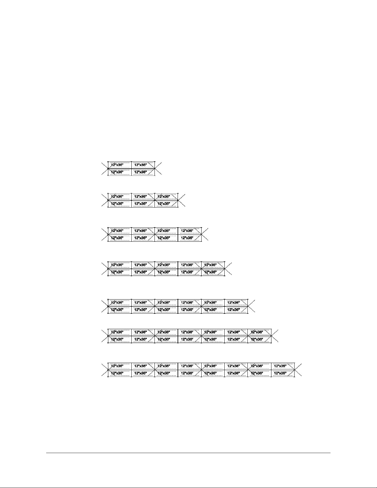
CORNER GUSSETS
Use gussets to ensure rigidity of the sec-
tion when you are not using back braces and
back pannels. Second gusset hole must be
drill on location after levelling the unit, do not
use tek screw.
4 pairs of gussets every 2nd section
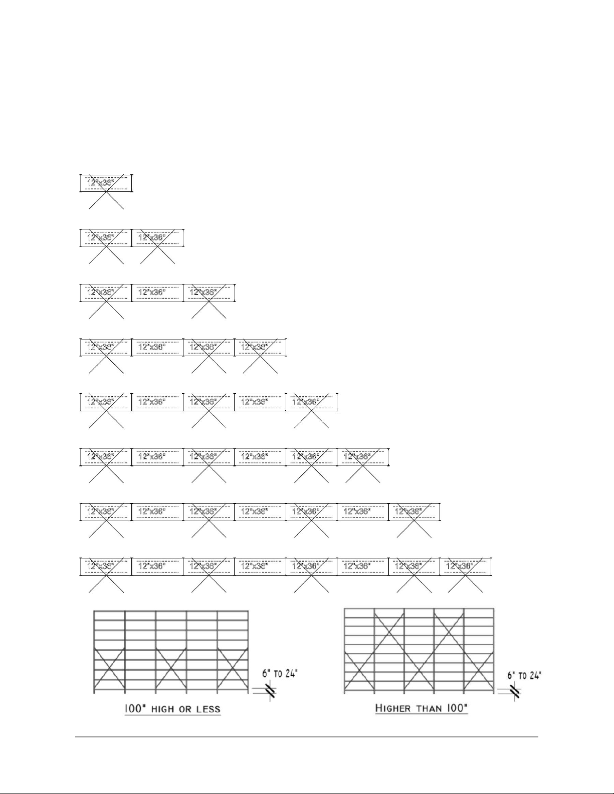
Use two hooks per hole to place
units side by side. Below are example of ways
to position the braces:
BASEPLATE
Slide the base plate, use base snap to lock
into place.
TIE CLIP
Install tie clips at the top and bottom of every sec-
tion with side braces.
DIVIDERS
4 dividers clips are needed per dividers.
SLIDING DIVIDERS
2 dividers clips are needed per dividers.
(514) 937-9533 / (833) 937-9533 / [email protected]
6/20
2020-07
2020-07
www.metalware.ca

Sub-Assembly Component Reference Guide
a. Footplates
● (1x) Footplate per post
● Footplates can be 2-½” x 3” x 1”
galvanized, 2-½”x 3” x 3/16” painted
or 4” x 5” x 1/4”
● They are bolted to the base of the
post using ¼”-20UNC x ⅝” bolt with
¼” lock nut
● (1x) ⅜” x 3” anchors are required per
footplate
● One “H” shelf clip is needed to
support the first shelf clip. Only one
shelf clip per post is needed to
support the shelf on either side
b. Splice bracket
● Splice brackets are used to connect two posts or panels
vertically
● They are made up of a pair of L-shaped ⅛” thick x 7-½”
long galvanized plates
● Splice brackets are bolted using (4x) ¼”-20UNC x ⅝”
bolts and nuts
7/20(514) 937-9533 / (833) 937-9533 / [email protected]
2020-07
www.metalware.ca

c. Cross aisle bracket
● Cross aisle brackets are used to connect custom
floor channels, top ties or lighting support
components
● They are made up of a pair of 12ga brackets
● Cross aisle brackets are bolted using (2x)
5/16”-18UNC x 5/8” bolts and nuts on each bracket
d. Down aisle bracket
● Down aisle brackets are used to connect custom
floor channels, top ties or lighting support
components
● They are made up of a pair of 12ga brackets
● Down aisle brackets are bolted using (2x)
5/16”-18UNC X 5/8” bolts and nuts on each
bracket
8/20
(514) 937-9533 / (833) 937-9533 / [email protected]
2020-07
www.metalware.ca

e. Shelves
i. 1in Clip
● 1” clips are used to support the
shelf with a 1” vertical
adjustability
● They are made of 16ga
galvanized steel
ii. 2in Clip
● 2” clips are used to support the shelf
with a 2” vertical adjustability
● They are made of 12ga galvanized
steel
9/20
(514) 937-9533 / (833) 937-9533 / [email protected]
2020-07
www.metalware.ca

f. Back panels
● Back panels are used to close the back of a
unit, and simultaneously acting as a brace
● They are made of 24ga steel
● Back panels are connected to the post using
specific clips and (2x) 1/4”-20UNC x 5/8”
bolts and nuts per clip
● Back panels clips are used to connect the
back panel with the post
● They are made of 12ga steel
● Maximum vertical spacing should be 28”
10/20
(514) 937-9533 / (833) 937-9533 / [email protected]
2020-07
www.metalware.ca

g. Floor channel
● Floor channels are used to support
flooring by connecting the post on both
ends, with a 2” vertical adjustability
● They are made of 14ga steel
● Floor channels are connected to the
post with a pin and 1/4”-20UNC x 5/8”
bolt, and lock nuts on both ends
h. Cross channel
● Cross channels are used to
support a floor and add
rigidity to the floor channel
● They are made of 14ga
steel
● Cross channels are bolted
to the floor channel with a
(2x) 12ga lug, using (6x)
1/4”-20UNC x 5/8” bolts
and nuts
11/20
(514) 937-9533 / (833) 937-9533 / [email protected]
2020-07
www.metalware.ca

i. Guardrail
● Guardrails are made of 1.5” x 1.5” x 1”
HSS
● They are connected to the post using
(2x) guardrail clips, (1x) 1/4”-20UNC x
5/8” and (1x) 5/16”-18UNC x 2.5” bolts
and nuts
j. Back-to-back tie clip
● Back-to-back brackets connect back-to-back posts
● They cannot be used in row with a closed back
panel, except on either end of the row
● They are made of 12ga steel
● Back-to-back brackets are bolted to the post of each
unit with (1x) 1/4”-20UNC x 5/8” bolt and nut
● Please refer to annex A for accurate pattern
12/20(514) 937-9533 / (833) 937-9533 / [email protected]
2020-07
www.metalware.ca

k. Side brace
● Side braces are used to reduce longitudinal
deflection
● They are made of 11ga steel
● Side braces come in pairs and are bolted to the post
using (4x) 1/4”-20UNC x 5/8” bolts and nuts
● Please refer to annex B for installation pattern unless
a specific drawing is provided
l. Back brace
● Back braces are used to reduce lateral
deflection
● They are made of 11ga steel
● Back braces come in pairs and are
bolted to the post using (4x) 1/4”-20UNC
x 5/8” bolts and nuts
● Please refer to annex C for installation
pattern unless a specific drawing is
provided
13/20
(514) 937-9533 / (833) 937-9533 / [email protected]
2020-07
www.metalware.ca

m. Divider
● Dividers are made of 22ga steel
● They are locked in place using (4x)
dividers clips, clipped into the shelf
● Dividers on top of each other share
the same dividers clips
n. Sliding divider
● Sliding dividers are made of 22ga steel
● They are locked in place using (2x) divider
clips, clipped into the shelf
14/20
(514) 937-9533 / (833) 937-9533 / [email protected]
2020-07
www.metalware.ca

o. Half divider
● Half dividers are made of 18ga steel
● They are bolted to the shelf using (2x)
1/4”-20UNC x 5/8”
15/20
(514) 937-9533 / (833) 937-9533 / [email protected]
2020-07
www.metalware.ca
Annex A
Back to back bracket position in aisle.
16/20(514) 937-9533 / (833) 937-9533 / [email protected]
2020-07
www.metalware.ca

Annex B
Side brace position in the aisle.
17/20(514) 937-9533 / (833) 937-9533 / [email protected]
2020-07
2020-07
www.metalware.ca
Annex C
Back brace position in aisle.
18/20(514) 937-9533 / (833) 937-9533 / [email protected]
2020-07
www.metalware.ca

MELWARE
2020-07

Table of contents
Other Metalware Storage manuals


Popular Storage manuals by other brands

Supero
Supero 5028R-E1CR12L user manual

Tabernus
Tabernus Enterprise Erase E2400 user guide

Quantum
Quantum PX506 Unpacking and installation instructions

Tandberg Data
Tandberg Data SLRTAPEDRIVE - Installation and user guide

PANTRYCHIC
PANTRYCHIC Smart Storage System quick start guide

Medion
Medion LIFE S88400 instruction manual


