Metcalfe EC12 User manual

Metcalfe EC12
Electrically Operated Potato Chipping Machine
Instruction Manual


INDEX
Delivery 3
Introduction 3
Chipper Dimensions 3
Installation 4
Electricity Supply Connection 4
Commissioning 5
Operation 5-6
Knife Block Fitting 6
Change Chip Size 6
Cleaning 7
Changing Knife Blades 7
Wiring Diagram for Chipper 8
Exploded View 9
Electrical Control Parts 10
Parts List 11-12
Spare Parts & Service 13
Metcalfe Warranty 14

DELIVERY
The packaged machine consists of one chipper unit and one instruction booklet. Please notify
both the carrier and the supplier within three days of receipt if anything is missing or damaged.
Check that the correct machine has been supplied and that the voltage, marked on the rating
plate, is suitable for the supply available. The rating plate is located on the right-hand side of the
case.
INTRODUCTION
The chipper is intended for cutting peeled potatoes into chips or scallops, in a batch process.
CHIPPER DIMENSIONS
All dimensions are in mm.

INSTALLATION
For the Installer:
These instructions contain important information designed to help the user obtain the maximum
benefit from the investment in a Metcalfe Chipper.
Please read them carefully before starting work, and consult with the supplier in the event of
any queries.
Be sure to leave this Instruction Manual with the user after installation of the machine is
complete.
Procedure
The unit is designed to stand on a bench, table, or on a draining board. Ensure that whatever is
used for this purpose is sturdy and rigid and not more than 750 mm high. A higher table makes
it difficult to load the machine.
The Chipper should be placed where supplies of peeled potatoes from the peeling machine are
readily accessible, after which the output of chips need to be in easy reach of the fryer.
The EC12 Chipper has a top loading hopper into which potatoes can be tipped from either side
or from the front. It is not handed, and no consideration need be given to its loading direction.
The discharge of chips is from the chute at the front of the machine, and the machine should be
placed so that this chute is directly over the receiving container.
ELECTRICITY SUPPLY CONNECTION
A Wiring Diagram is shown on Page 9.
Position the Chipper in the chosen site. The electricity supply connection should be made to a
power outlet socket or isolator mounted on the wall close to the machine. This socket or isolator
must be accessible once the machine is installed. Before connecting, check that the voltage
shown on the rating is correct for the electricity supply you have available. The outlet should be
fused at 13 amps.
NOTE: The plug is fitted with a 10amp fuse.
WARNING: This machine must be earthed.
Should the supply cord become damaged then an approved electrician must fit a replacement.
The IEE Codes of Practice must be observed.
An equipotential bonding terminal is provided at the back of the unit near the cable outlet for
external earth bonding. Provision of an earth bond does not remove the requirement for an
earth in the electrical supply.

COMMISSIONING
Open the hopper by fully unscrewing the interlock knob at the front and lifting up until the
hopper is fully resting back on its hinges. Turn the rotor by hand to ensure that it is completely
free to rotate and that the knife block assembly is properly in position. Replace the hopper and
screw down the interlock knob until it is tight.
It is now safe to switch on at the wall socket and to start the machine by pressing the start button
on the front of the machine (green button). To stop the machine, press the red button.
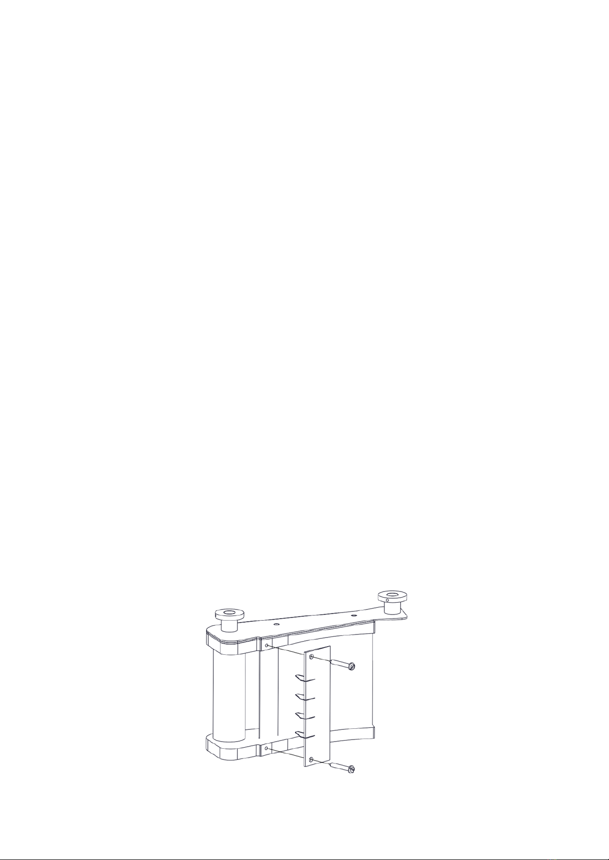
One of the safety features provided on the Metcalfe Chipper are the interlock devices that
ensures that the machine cannot run unless both the knife block and the hopper are properly
and fully in position. This makes it impossible for the operator to touch the spinning rotor whilst
it is running.
To confirm that the interlock is operating correctly press the start button to switch the machine
on. Then whilst it is still running, unscrew the hopper interlock knob. After two or three turns
the machine should switch off, but there are still two or three further turns of the knob necessary
before the hopper can be opened. The rotor should be stationary within 2 seconds of the hopper
being opened. If the knife block is not in place, another interlock will prevent the machine from
running.
OPERATION
With the machine running, feed peeled potatoes into the hopper. It will hold approximately 15kg
of potatoes, which self-feed into the mechanism of the machine and discharge as cut chips from
the chute.
Some care is necessary when loading, as the rotor will not accept abnormally large potatoes, so
these must be cut into two. The hopper is specially designed not to pass potatoes which are over
size and which could otherwise clog the mechanism. It is also essential that only potatoes be fed
in to this machine.
NOTE: take great care to ensure that there are no stones mixed in with the potatoes.
A stone or any other foreign object will damage the cutting knives and could cause the machine
to jam. In this event the machine has an inbuilt protection device, which will switch it off before
the electric motor burns out. This overload protection feature will automatically reset itself
when it cools down but it is necessary to wait a few minutes for this to happen. After clearing
the jam resume operation by pressing the start button. Should a stone damage the knife blades
they must be replaced as further use could break the blades.
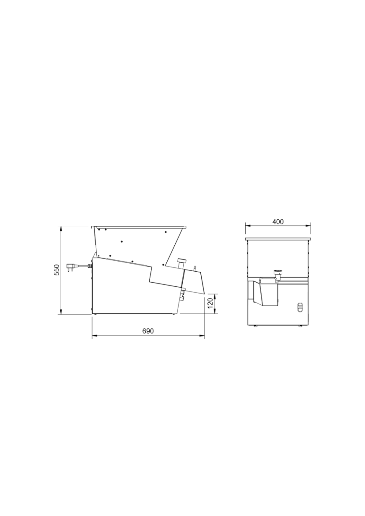
This Chipper is designed for batch process work; switch the machine off once all the potatoes
have been cut. The motor is fitted with a thermal trip that will stop the machine if the motor
overheats. This protection feature will automatically reset itself when it cools down but it is
necessary to wait a few minutes for this to happen.
The machine will switch itself off in the event of failure of the electricity supply whilst operating.
When the supply is restored the machine must again be switched on. It is fitted with no-volt
release.
KNIFE BLOCK FITTING
CHANGE CHIP SIZE
To change to a different size of chip, change the knife block assembly. Spare knife block
assemblies are available from Metcalfe. Open the hopper, lift out the knife block and replace
with the alternative selected. Knife blocks are available in the following sizes from the standard
range: 12mm, 14mm, 14 x 17mm and 17 x 21mm.
3. Tighten the front knob to
fully secure the knife block
2. Push down on the rear knife
block fixing knob whilst screwing
down firmly to tighten
1.
Place the knife block in the recess of the
chipper. Ensure the base of the knife
block fits correctly on the location pins.

CLEANING
It is essential to clean the machine at least once a day, preferably at the end of each period of
operation.
1. Switch off at the socket or isolator
2. Fully unscrew the interlock knob, open the hopper and lift it out of its hinge seating at the
back
3. Clean the hopper in a sink, dishwasher, pot wash or by hosing with a spray
4. Remove the knife block by lifting upwards, off its locating dowels
NOTE: Take care when handling the knife block. The blades are sharp.
5. Clean the knife block underaspray or running tap and remove any residual pieces of potato.
Visually inspect all blades for wear or damage, and replace the knife pack as necessary. Do
not attempt to straighten a bent blade - bent blades should be replaced immediately.
6. Lift the rotor carefully off its spindle.
7. Clean the rotor in a sink, pot wash, etc.
8. Clean out the interior of the base unit and wipe over the exterior with a damp soft cloth.
Do not hose down the exterior of the machine.
DO NOT USE CLEANING MATERIALS CONTAINING ABRASIVES OR BLEACHES.
9. Reassemble the machine, reversing the above disassembly procedure.
When replacing the rotor, ensure that it is put back square on its spindle. Make sure that it
is properly seated on its cross pin by turning it slowly until it drops onto this seating. When
replacing the knife block it should slip down easily on to its dowel pins, make certain that it
is fully down.
CHANGING KNIFE BLADES
The knife blades are supplied as a pack and individual blades cannot be changed. Change the knife
blade pack as soon as it is damaged or blunt. To change the knife blade pack remove the knife
block and undo the two screws securing the knife blade pack. Dispose of the old blades carefully
and screw the new knife blade pack in place. See diagram below.
For optimum performance Metcalfe recommend changing the blade pack every 6 months, or
sooner depending on usage.
NOTE: Take care when handling the knife block. The blades are sharp.

EC12 WIRING DIAGRAM

EXPLODED VIEW

ELECTRICAL CONTROL PARTS

PARTS LIST
ITEM
PART NO
DESCRIPTION
1
S61/150
HOPPER ASSEMBLY, INCORPORATING:
1a
M81A
INTERLOCK BODY & MAGNET
1b
A12/011
INTERLOCK SPRING
1c
L61/024
HOPPER KNOB
1d
D26/017
INTERLOCK PIN
2a
S61/184
21x17mm KNIFE BLOCK
S61/145
12mm KNIFE BLOCK
S61/151
14mm KNIFE BLOCK
S61/144
14x17mm KNIFE BLOCK
2b
S61/183
21x17mm KNIFE PACK ASSY
S61/134
12mm KNIFE PACK
S61/129
14mm KNIFE PACK
S61/128
17mm KNIFE PACK
3
C61/002 M1 Z
ROTOR
4
S61/178
HOPPER MAGNETIC SWITCH ASSY
5
S61/179
KNIFE BLOCK MAGNETIC SWITCH ASSY
6
D19/138
SCREW M5 X 8 SKT BUTTON HEAD
7
L61/025
KNIFE BLOCK LOCATING PIN, INCORPORATING:
7a
D25/003
SPRING WASHER M10 S.S.
7b
D20/015
M10 FULL NUT S.S.
8
L34/005
KNIFE BLOCK SHORT PIN, INCORPORATING:
8a
D25/052
PLAIN WASHER M6 ST STEEL
8b
D20/013
NUT M6 FULL SS
9
G45/109
PUSH BUTTON RED & GREEN, INCORPORATING:
9a
G45/110
BOOT FOR PUSH BUTTON
9b
G45/111
BUTTON CONTACTORS NO & NC
10
A13/024
HOPPER TRUNNION, INCORPORATING:
10a
D25/033
WASHER M4 SHAKEPROOF S.S.
10b
D19/120
SCREW M4 X 8MM HEX S.S.
11
S61/176
ELECTRIC PANEL ASSY, INCORPORATING:
11a
E61/133
REAR PLATE
11b
G60/101 M4
PLUG & CABLE ASSY
11c
A10/266
M20 CABLE GLAND BLACK
11d
A10/224
M20 GLAND LOCKNUT
11e
G35/012
FUSE HOLDER
11f
G35/004
FUSE 0.5A SEMI DELAY
11h
G30/343
24V AC MINI CONTACTOR
11i
G60/427
TRANSFORMER TERMINATED
11l
D19/110
SCREW M4 X 10MM HEX.S.S.
11m
D25/033
WASHER M4 SHAKEPROOF S.S.
11n
D20/011
NUT M4 FULL S.S.

ITEM
PART NO
DESCRIPTION
11o
D25/004
WASHER M5 SHAKEPROOF
11p
D20/038
NUT M5 FULL S.S.
11q
D25/062
LOCK WASHER M8 S.S.
11r
D20/014
M8 FULL S.S. NUT
12
K08/043
GASKET STRIP
13
S61/177
MOTOR ASSY, INCORPORATING:
13a
E61/014
MOTOR MOUNTING BRACKET
13b
D19/032
SCREW M5 X 12MM HEX S.S.
13c
D19/115
SCREW M6 X 30MM HEX S.S.
13d
D20/013
NUT M6 FULL SS
13e
A06/099
DRIVE PULLEY WITH KEYWAY
13f
L61/041
BUSH (FOR DRIVE PULLEY)
13g
D19/142
SCREW M4 x 25L HEX SS (FOR DRIVE PULLEY)
13h
G60/323
MOTOR CABLE ASSY 1PH
14
S61/118
BEARING HOUSING ASSEMBLY
15
A02/068
O-RING
16
E61/015
DRIVE BRACKET
17
D25/052
PLAIN WASHER M6 ST STEEL
18
D25/005
WASHER M6 SHAKEPROOF S.S.
19
D20/013
NUT M6 FULL S.S.
20
D19/038
SCREW M6 X 12MM HEX S.S.
21
D27/031
DRIVE KEY
22
A06/090
DRIVE PULLEY 114-5M-25F
23
D25/019
M6 WASHER 25OD
24
A05/041
DRIVE BELT 850 - 5M - 25
25
E61/107
BASE PLATE
26
A13/108
FOOT, BLACK POLYTHENE
27
D21/044
M5 X 12 PAN HEAD SCREW
28
D25/004
WASHER M5 SHAKEPROOF
Note: The parts list is for 230V 1ph 50Hz machines. For electrical parts for other voltages please
contact our spares department.

SPARE PARTS AND SERVICE
For more information on Metcalfe spare parts, accessories and service support, please contact
us on the details below.
Please always quote the Serial Number of the machine. This can be found on the serial number
plate which is located on the rear of the machine.
Metcalfe Sales & Spares Department sales@metcalfecatering.com
Metcalfe Service Department service@metcalfecatering.com
Metcalfe Website www.metcalfecatering.com
Metcalfe Telephone Number 01766 830 456
Additional copies of this instruction manual can be obtained by either visiting our website or
contacting the sales department.

METCALFE WARRANTY
All Metcalfe products are guaranteed against defects in material and workmanship for a period
of one year from date of Invoice, except where specially noted.
The Company's obligation under this warranty is limited to repairing or replacing, without
charge, any part or parts found to be defective under normal use, in accordance with the
specified operations manual and capacity ratings.
On all return to factory warranty items, it is the responsibility of the purchaser to return the
entire unit to the factory, in a clean condition, properly packed and labelled.
All repairs, alterations or replacement of materials or parts not authorised by Metcalfe will
automatically void all warranties in their entirety.
All Metcalfe slicers (except Simple Line) are covered by a 2-year warranty (1st year parts and
labour, 2nd year parts only) and full after sales service.
All Metcalfe MP mixers are covered by a 3-year warranty (1st year parts and labour, 2nd & 3rd
year parts only) and full after sales service.
There is a limited 6-month warranty on the following:
•Mixer attachments (beater, whisk and dough hook)
•Parts purchased or supplied for the repair of Metcalfe equipment
This warranty does not cover the following:
•Failure due to neglect, abuse, careless handling or misuse of machine
•Failure caused due to improper maintenance
•Blender clutches
•Knives and gears on can openers
•Sharpening of slicer blades
•General wear and tear
Metcalfe and its suppliers reserve the right to make changes in design and specification to any
product without prior notification.

Other products in the Metcalfe portfolio:
NS Slicer Range
Peeler Range
Ceado Roband
5/2022
Metcalfe Catering Equipment Ltd
Haygarth Park
Blaenau Ffestiniog
Gwynedd, LL41 3PF
t 01766 830 456 e sales@metcalfecatering.com wwww.metcalfecatering.com
Other manuals for EC12
1
Table of contents
Other Metcalfe Chipper manuals