Metek Apollo XF Octane User manual

Apollo XF/XLT/Octane
Basic User
Guide
Rev. 1.5
June 24, 2016


Contents
Octane Basic User Guide
Page 3 of 25
Table of Contents
1 Introduction .......................................................................................................................................... 5
1.1 Detector Types.............................................................................................................................. 5
2 Safety Precautions ................................................................................................................................ 7
2.1 High Voltages ................................................................................................................................ 7
2.2 Not Hot Swappable ....................................................................................................................... 7
2.3 Cooling .......................................................................................................................................... 7
2.4 Motorized Slide............................................................................................................................. 7
2.5 Radiation safety ............................................................................................................................ 8
2.6 Extending Detector Window Life .................................................................................................. 8
2.6.1 Do not allow the detector to come into close proximity or contact with high voltage
components .......................................................................................................................................... 8
2.6.2 Prevent particle contamination inside the sample chamber................................................ 9
2.6.3 Proper care when using a compressed gas to vent the sample chamber ............................ 9
2.6.4 Avoid hitting the detector or inducing mechanical vibrations in the detector or SUTW ..... 9
2.6.5 Avoid touching the window ................................................................................................ 10
2.6.6 When not in use leave the SEM in high vacuum mode ......................................................10
2.6.7 Do not expose the detector to extreme temperatures ...................................................... 10
2.6.8 Do not expose the SUTW to plasma ...................................................................................10
2.6.9 Windowless detectors.........................................................................................................10
3 Installation and Environment Requirements...................................................................................... 11
3.1 Power requirements ................................................................................................................... 11
3.2 Space and Weight specifications ................................................................................................ 11
3.3 Environment requirements.........................................................................................................11
4 Basic Detector Operation.................................................................................................................... 13
4.1 Startup ........................................................................................................................................ 13
4.2 Detector Cooling .........................................................................................................................13
4.2.1 Status LEDs.......................................................................................................................... 14
4.2.2 Using an Octane detector with TEAM software .................................................................15
4.2.3 Using an Octane detector with Genesis Software .............................................................. 16
4.3 Motorized Detector .................................................................................................................... 17
4.4 Adding to company network....................................................................................................... 17
4.5 Light Element Operation.............................................................................................................18
4.6 Frequently Asked Questions (FAQ)............................................................................................. 18
5 Basic System Cabling........................................................................................................................... 19
5.1 Typical Workstation configuration.............................................................................................. 19
5.2 Typical Microscope System configuration (SG-2) .......................................................................20
5.3 Typical Dual Detector Microscope System configuration...........................................................21
5.4 Typcial Microscope System Interconnect (SG-3) ........................................................................22
6 Troubleshooting..................................................................................................................................25
6.1 Remote Diagnostics ....................................................................................................................25
6.2 Detector Problems ......................................................................................................................25

Contents
Octane Basic User Guide
Page 4 of 25
This page is intentionally left blank

Introduction
Octane Basic User Guide
Page 5 of 25
1INTRODUCTION
The detector is a sophisticated precision instrument.
Removal of any system’s covers must be done by
qualified EDAX Factory trained engineers or
representatives.
All User / Operator adjustments and calibrations are done within the TEAM or Genesis software
environment. Users of the system should not attempt removing any covers or making any service
adjustments.
Proceed with caution where the following label is found.
Please send feedback regarding this manual to:
edax.suppo[email protected]
1.1 DETECTOR TYPES
The detectors listed in the table below are covered by this basic user guide. Note that a “W” in the
detector part number on the label, indicates the detector is a Window-less detector.
Name
Description
Octane Pro
10 mm2SUTW for SEM
Octane Plus
30 mm2 SUTW for SEM
Octane Super
60 mm2 SUTW for SEM
Octane Ultra
100 mm2SUTW for SEM
Apollo XF
60 mm2 SUTW for SEM
Octane Prime1
10 mm2SUTW for SEM
Apollo XLT
30 mm2 SUTW for TEM
Apollo XLT2
30 mm2 SUTW for TEM
Apollo XLT W
30 mm2Windowless for TEM
Apollo XLT Light Shield
30 mm2Windowless w/Light shield for TEM
Apollo XLT2 W
30 mm2 Windowless for TEM
Apollo XLT2 Light Shield
30 mm2Windowless w/Light shield for TEM
Octane T Ultra W
100 mm2Windowless for TEM (Racetrack)
Octane T Optima - 30
30 mm2 Windowless for TEM
Octane T Optima - 60
60 mm2 Windowless for TEM
Octane T Plus
30 mm2 SUTW for TEM
Table 1 - Detector models
1
See Technical specifications for differences from Octane Pro and limitations
Removing any of the instrument
covers, may pose a safety hazard as high
voltages may be exposed.
Do not attempt to use until fully
understanding its proper connections and
functions. Users should have a basic
understanding of the operation of the
system before operating.

Introduction
Octane Basic User Guide
Page 6 of 25
This page is intentionally blank
Safety Precautions
Octane Basic User Guide
Page 7 of 25
2SAFETY PRECAUTIONS
Use the following safety guidelines to help ensure personal safety and to help protect the detector
system from potential damage.
2.1 HIGH VOLTAGES
Exercise extreme caution where this label is found. High Voltage is present and can cause burn,
shock and/or cause serious injury.
There is circuitry in the detecting unit that generates high voltage (200 VDC) required to
bias the detector. Terminals carrying these voltages may be exposed when covers or panels are
removed.
2.2 NOT HOT SWAPPABLE
The electronics are NOT hot swappable unless otherwise specified. The power to the system must
be turned off before inserting or removing any of the modules, boards or any of the interconnecting
cables. If this precaution is not taken, component will be damaged nearest to the connecting pins.
2.3 COOLING
The detecting unit is cooled by the detecting unit body’s heat sink fins. No fans are used, just
ambient cooling via the heat sinks. Be sure these heat sinks are not blocked or covered. Keep away from
heat radiators or other heat sources. The detectors may fail if used in an enclosure with inadequate air
cooling.
2.4 MOTORIZED SLIDE
Warning! Pinch Hazard!
Fingers may be squeezed when operating the detector optional motorized slide.
□Do not place fingers or hands near the detector when operating the motorized slide.
Safety Precautions
Octane Basic User Guide
Page 8 of 25
2.5 RADIATION SAFETY
The electron microscope generates ionizing radiation when the electron beam is energized. The
detector is designed to have radiation leakage far less than the allowable level when properly mounted
with all covers and shielding in place.
EDAX warrants that its detectors and microscope interfaces when assembled and installed per EDAX
Engineers or Representatives, will provide Radiation Safety performance levels that will be in
compliance with the original Microscope design specifications.
Removal of any of the system's covers must be done by qualified EDAX Factory trained service engineers
or representatives. Opening covers or bypassing interlocks may expose users to radiation.
If the EDAX detector is removed from the microscope, it should be replaced by the original blanking port
cover provided by the microscope vendor.
Modification of covers or shielding or use of any other material than provided by EDAX or the
microscope vendor must be reviewed by a certified radiation expert and EDAX Inc. before use.
Caution: The radiation levels should be checked around the instrument after any service in which
covers or any radiation containment parts were removed.
2.6 EXTENDING DETECTOR WINDOW LIFE
Introduction
Super Ultra-Thin Windows (SUTW) for EDS detectors were introduced to the EDS market several years
ago to improve the transmission of low energy X-rays (e.g. B, C, N, O) through the window. The SUTW is
constructed of a 300 nm thick polymer foil with an additional 40 nm of coatings to reduce visible light
transmission and permeability. The polymer window is stretched over a silicon grid which provides
support over larger areas. The goal of the window is to allow signal X-rays to pass through to the
detector component while providing a hermetic seal on the atmosphere surrounding the detection
element. While the SUTW serves its intended purpose very well, it can be damaged if care is not taken
by users of the EDS system into which the window is installed.
Recall that the overall window thickness is approximately 340 nm, which is 150 times thinner than the
average human hair. When the window is damaged, this contaminates the atmosphere surrounding the
X-ray detector which in turn can degrade detector performance or cause failure. Damage to the SUTW
can be caused by physical contact, excess vibration, exceeding pressure or temperature specifications,
vapor condensation, electrical discharge to the detector or other factors.
2.6.1 DO NOT ALLOW THE DETECTOR TO COME INTO CLOSE PROXIMITY OR CONTACT
WITH HIGH VOLTAGE COMPONENTS
Do not allow the detector to come into close proximity or contact with high voltage components inside
the electron microscope, e.g. the extraction grid of a video detector. This can lead to an unsafe electrical
discharge to the detector which may damage the window.

Safety Precautions
Octane Basic User Guide
Page 9 of 25
2.6.2 PREVENT PARTICLE CONTAMINATION INSIDE THE SAMPLE CHAMBER
Particulates inside the sample chamber have a tendency to become entrained in the gas flow while
venting the sample chamber. The gas flow during a chamber vent or increase in chamber pressure is
generally turbulent meaning that entrained particles can fly in all directions, including toward the
detector window. Particulates which impact the window can cause micro cracks compromising the
vacuum seal of the window. In more extreme situations, particles can fully penetrate the window
causing what is known as a “bullet hole”, which causes a larger leak in the detector. It is also possible to
dislodge particles from the sample via the electron beam. If these particles are charged, they may be
accelerated toward the detector, which is at ground potential.
Recommendations:
• Always use particle free gloves when loading samples or working in the sample chamber.
• Be certain that there are no loose particles on the sample before placing the sample in the chamber.
Sample surfaces, fractures and powdered samples stuck to an adhesive should be cleaned with
compressed air to ensure the surfaces are clean and free of loose particles.
• Avoid venting the sample chamber too quickly. Specifically, do not exceed 10 cm/s gas velocity into
the chamber, as this can increase the risk of particle-induced detector window damage. This may
require a small aperture in the vent port or decrease in supply pressure if N2 purge is used to reduce the
gas velocity.
• If there is a high risk of particulates becoming dislodged during some operation in the microscope,
fully retract the detector to minimize the risk of damaging the detector window.
2.6.3 PROPER CARE WHEN USING A COMPRESSED GAS TO VENT THE SAMPLE CHAMBER
Ensure that the gas pressure does not exceed 2 atm.
Recommendations:
• Release any latching mechanism that is designed to keep the chamber door closed.
• Make certain that the chamber door will open normally when the chamber reaches atmospheric
pressure.
• Avoid venting the chamber too quickly as this can cause unsafe pressure-induced vibrations on the
window. See recommendations in section 2.6.2 above.
2.6.4 AVOID HITTING THE DETECTOR OR INDUCING MECHANICAL VIBRATIONS IN THE
DETECTOR OR SUTW
The SUTW can be ruptured by excessive physical vibration or shock.
Recommendations:
• Be careful not to run samples into the EDS detector.
• Close the sample chamber door gently.
• Do not pull the sample chamber door open while venting the sample chamber. This may lead to unsafe
pressure fluctuations inside the sample chamber which could damage the detector window.

Safety Precautions
Octane Basic User Guide
Page 10 of 25
2.6.5 AVOID TOUCHING THE WINDOW
Recommendations:
• Exercise extreme caution when working near the SUTW. The collimator provides a physical barrier to
protect the SUTW. Do not work with tools near the SUTW.
• If it is necessary to remove the collimator, the collimator should be removed and installed by a trained
technician so as not to touch the window or stress the end cap tip.
• Do not direct pressurized gas or liquid streams at the SUTW, for example in an attempt to clean the
SUTW.
• If necessary to clean the microscope chamber, retract or remove the detector using extreme caution
not to bump the detector tip or collimator.
2.6.6 WHEN NOT IN USE LEAVE THE SEM IN HIGH VACUUM MODE
If possible, leave the SEM in High Vacuum mode instead of in low vacuum or wet mode.
2.6.7 DO NOT EXPOSE THE DETECTOR TO EXTREME TEMPERATURES
Be mindful of conditions which may cause vapor condensation on the window or may cause the
temperature at the window to exceed manufacturer’s specifications. This may occur during a
microscope chamber bake or operation of a heat stage.
Recommendations:
• If there is a possibility that the sample may emit vapors while in the sample chamber, especially vapors
acidic or alkaline in nature, fully retract the EDS detector to minimize the risk of condensation on the
detector window.
• Take care when using a heating stage to follow manufacturer’s guidelines. Prior to using the heat
stage, confirm the EDS detector window type and temperature specifications as well as the heat load on
the EDS window during operation of the heating stage.
• The maximum temperature specification on Moxtek AP3 windows is not to exceed 40°C with 1 atm
differential or 70°C with zero pressure differential on the window.
2.6.8 DO NOT EXPOSE THE SUTW TO PLASMA
The window manufacturer of the SUTW does not recommend exposing the window to a plasma
generated by a plasma cleaner.
2.6.9 WINDOWLESS DETECTORS
Care should be taken to allow the detector to warm before venting the microscope to air. Failure
to do so may damage the detector module.

Installation Requirements
Octane Basic User Guide
Page 11 of 25
3INSTALLATION AND ENVIRONMENT REQUIREMENTS
Keywords: Room requirements, power needed, electrical requirements
3.1 POWER REQUIREMENTS
Component
XM2 Configuration
Workstation Power
400 watts (maximum); 100-240 Volts, 50/60 Hz, 3.5 to 7.0 Amps
Monitor
25 watts (typical) ; 100-240 Volts, 50/60 Hz
Detector
75 watts; 100-240 Volts, 47-63 Hz, 0.5 to 1.25 Amps
Table 2 - Power requirements
3.2 SPACE AND WEIGHT SPECIFICATIONS
Workstation dimensions: 17.5 (H) x 7.75 (W) x 19.5 in (44 x 20 x 49.5 cm)
Workstation weight: 33.0 lb. (14.97 kg)
Detector Body dimensions 4.375 (W) x 4.375 (H) x 6.75 in (L) (110 x 110 x 165 mm)
Detector Weight 8 lb. (3.63 kg)
3.3 ENVIRONMENT REQUIREMENTS
Parameters
Operating Conditions
Temperature
+5C to +30C
Humidity
0% to 85% RH, non-condensing
Barometric Pressure
525 to 800mm of Hg
Air Velocity
0 to 0.5m/sec
Table 3 - Environment requirements / Operating conditions

Installation Requirements
Octane Basic User Guide
Page 12 of 25
This page is intentionally blank
Basic Detector Operation
Octane Basic User Guide
Page 13 of 25
4BASIC DETECTOR OPERATION
4.1 STARTUP
A minimum EDS configuration consists of a PC Workstation with a Ethernet connection for the detector,
and the Detector, with its external power supply.
Start up the system as follows:
1. Power on the PC Workstation. The default Windows Login from the EDAX Factory is:
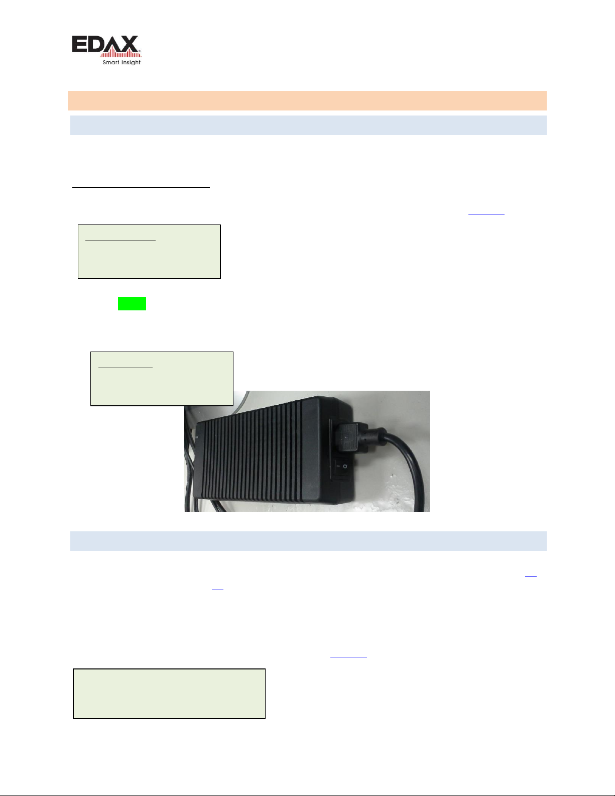
2. Power on the detector using the switch on the small “brick” style power supply. Figure 1
The detector communication is normally established within a couple of minutes after the PC has started.
There is a Green LED that will flash at the Ethernet connection on the detector when connected to the
Network board in the PC. This should be flashing rapidly (i.e. 10 flashes) /sec and continuously.
Then launch the TEAM or Genesis software. By default, there is an Administrator login set up for TEAM.
Figure 1 - Detector Power Supply
4.2 DETECTOR COOLING
By default, detector cooling is “Off”until it is started by the user. When the cooling is started, either in
Genesis or in TEAM, the detector should cool down in about 2 minutes. See the status lights on Page 14
or software indicators on Page 15, to see the status of the cooling, and when the detector is ready to
use. Spectra can be collected after the detector reaches its operating temperature, but for optimal
performance and stable peak positions, it may be best to wait about 60 minutes.
Note that when using the detector, a few microscope conditions may need to be met, and may require
the user to manually acknowledging the status is OK. See Figure 3 for Safety Interlocks.
Windows Login:
User: Administrator
Password: apollo
TEAM Login:
User: Administrator
Password: apollo
A Windowless detector should only be
cooled when the microscope chamber
is in high vacuum!

Basic Detector Operation
Octane Basic User Guide
Page 14 of 25
4.2.1 STATUS LEDS
There are two status LEDs located on the back panel of the detector. They function as follows:
Status 1 LED
Indication
Status 2 LED
Indication
RED
Warm
RED
Not ramping
Blinks YELLOW
Cooling
Blinks YELLOW
Cooling
Blinks GREEN
Near Operating Temp
Blinks GREEN
Ramping
GREEN
At Operating Temp
Blinks RED
Warming
Table 4 - Status LEDs definitions
When the detector is first powered ON both Status lights on the detector back panel will light RED.
There is a Yellow LED that should be lit at the Ethernet connection when powered ON.
There is a Green LED that will flash at the Ethernet connection when connected to the
Network board in the PC. This should be flashing rapidly (i.e. 10 flashes /sec) and continuously
before starting the Genesis or TEAM software.
Figure 2 - Detector Status Lights
Status LEDs
Basic Detector Operation
Octane Basic User Guide
Page 15 of 25
4.2.2 USING AN OCTANE DETECTOR WITH TEAM SOFTWARE
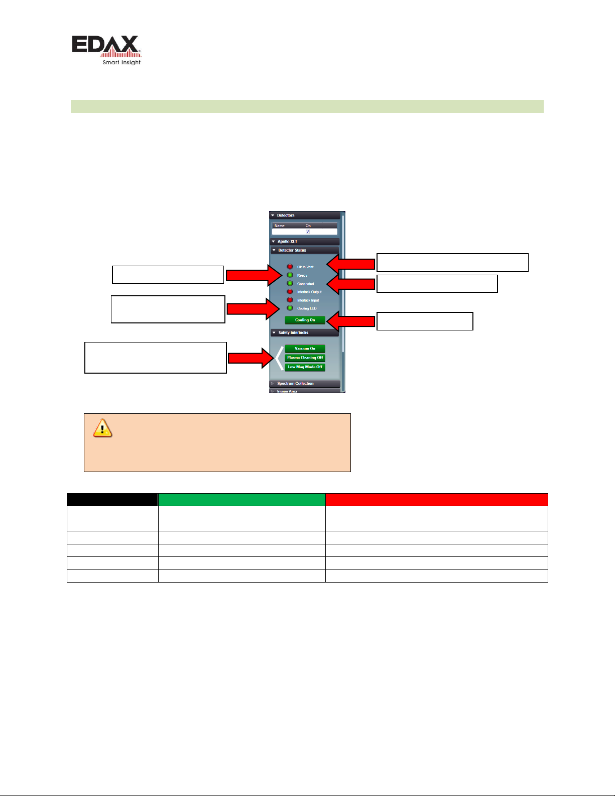
Check all detector functionality in the TEAM software. See the next section for Genesis software.
Turn the detector cooling on in the Detector Status area.
The detectors may be hardware or software interlocked with the microscope. Some or all may simply be software
buttons that the user must acknowledge that it is ok to cool the detector. Toggle each button so each Safety
Interlock is Green.
Figure 3 - Detector control and detector status in TEAM
Status Indicator
Green
Red
OK to Vent
DU is warm. OK to vent microscope
DU is cold. Not OK to vent microscope for Window-
less DU
Ready
DU is cold. OK to collect spectra.
DU is not ready to collect spectra
Connected
Communication with DU is OK
No communication with detector
Cooling LED
DU is cold, at Operating Temp
DU is Warm
Cooling On
Detector cooling is on
Detector cooling is off
Click on each to turn Green
All must be Green to turn cooling ON.
Click to turn on Cooling
This is the same as Status 1
LED on back of DU
Detector is communicating OK
DU ready to collect spectra
Detector is warm. OK to vent microscope
Care should be taken to warm a Windowless
detector before venting the microscope to air. Failure
to do so may damage the detector module!

Basic Detector Operation
Octane Basic User Guide
Page 16 of 25
4.2.3 USING AN OCTANE DETECTOR WITH GENESIS SOFTWARE
When a detector is used with the Genesis software, a small icon is placed in the Windows Task Tray that
provides control for the detector for cooling and driving the optional motorized slide.
The detectors may be hardware or software interlocked with the microscope. Some or all may simply be
software buttons that the user must acknowledge that it is ok to cool the detector. Toggle so each
Safety Interlock is Green.
Figure 4 - Detector control and detector status for Genesis
Click on each to turn Green
All must be Green to turn
cooling ON.
Click to turn on Cooling
This is the same as Status 1
LED on back of DU
Detector is communicating OK
DU ready to collect spectra
Detector is warm. OK to vent microscope
Care should be taken to warm a
Windowless detector before venting
the microscope to air. Failure to do
so may damage the detector
module!

Basic Detector Operation
Octane Basic User Guide
Page 17 of 25
4.3 MOTORIZED DETECTOR
If the detector is configured with a motorized slide, when a user wants to use the detector for analysis,
after cooling the detector, there will be a software control to insert the detector into the analyze
position. The control is in the TEAM software with the detector cooling controls, or in the Genesis
detector controls in the Task Tray.
Figure 5 - Motorized Slide Control
There are Slide controls in the TEAM Environment Panel as well as in the Advanced Properties Panel.
A detector with a motorized slide, will automatically retract from the Analyze position if it detects a high
count condition. This high count condition is normally set by the factory or installation service engineer.
The purpose is to protect the detector from high energy backscattered electrons in a TEM which can be
harmful to the detector. Under those conditions, the detector cooling may also be shut down.
4.4 ADDING TO COMPANY NETWORK
Care must be taken if the EDAX computer is added to a company network, the detector and its
Network Interface Card (NIC) IP information are NOT CHANGED. Changing any of the detector
networking configuration may cause the system to stop functioning.
EDAX service engineers will require Administrator login privileges to service the system.
The detector must be moved to the Analyze position to collect spectra and maps.
The detector should be moved to the Retract position when not in use.
Slide
Control
Retract the motorized slide detector before shutting down the system

Basic Detector Operation
Octane Basic User Guide
Page 18 of 25
4.5 LIGHT ELEMENT OPERATION
1. Check that the geometry is correct when collecting spectra. For example, an incorrect tilt used,
giving an incorrect Take Off Angle, will affect the Quant results. You can also correct this after
the data has been collected by editing the spectra file parameters.
2. Check that you are using a well-defined peak when quantifying. Avoid using peaks that are
“buried” in the background.
3. Use one of the longer amp times when specifically looking for light energy elements. They
typically provide better light element performance.
4. Use low accelerating voltage when specifically looking for light energy elements.
3. Make sure the samples are flat and homogeneous when possible.
4. Collect for sufficient time to improve the statics when the peaks are very small, for example
when looking at Boron.
4.6 FREQUENTLY ASKED QUESTIONS (FAQ)
Q1. Should I leave the detector powered on all of the time?
A1. In most laboratory conditions (stable power, temperature controlled), leaving the detector powered
on all of the time is fine.
Q2. Should I leave the detector cold all of the time?
A2.The detector will reach operating temperature in about two minutes, so it does not need to be left
cooled when not in use. Spectra can be collected after the detector reaches its operating temperature,
but for optimal performance and stable peak positions, it may be best to wait about 60 minutes. It is
okay to leave the detector cold when the microscope chamber is left under vacuum. There is a user
preference option in the software to automatically turn the cooling off after inactivity, in case the user
prefers to turn the cooling off automatically.
Q3. The software displays a message that the detector temperature is not changing, or a
communication problem with the detector. What should I do?
A3. In this case, power off the detector using the switch on the small black power “brick” for the
detector then reboot the PC. Then power the detector back on after Windows has started.
Q4. How often should I calibrate?
A4. Many labs only calibrate their systems during a regularly scheduled service preventative
maintenance visit. The detector will need to be calibrated in some cases when then spectrum peaks do
not match the blue line modeled peaks. For this case, a calibration will bring the peaks into alignment
with the modeled line. In other cases, labs may want to set a regular calibration schedule any time from
weekly to monthly.
Q5. What count rate should I use to calibrate?
A5. We recommend using a copper and aluminum sample with a primary beam at ≥ 20 kV. Adjust the
sample position so both Copper and Aluminum can be seen on the same screen. Set the position so the
Copper and Aluminum Kα peaks are similar in height, but with the Al peak larger than the CuK peak by
20 to 50%. Set the beam conditions so the Dead Time is ≤ 40% as you should use during normal use.

Basic System Cabling
Octane Basic User Guide
Page 19 of 25
5BASIC SYSTEM CABLING
5.1 TYPICAL WORKSTATION CONFIGURATION
Figure 6 - PC Workstation Connections
Power Supply
Air Flow
Hard drive
USB Restore
SG-3 Board
Fan
Air Flow
Internal Sync cable
Sync Panel
Network Board
Card bracket
Microscope
Beam Interface
cable
Ethernet cable
Sync cable
(RJ11)
Octane detector
Basic System Cabling
Octane Basic User Guide
Page 20 of 25
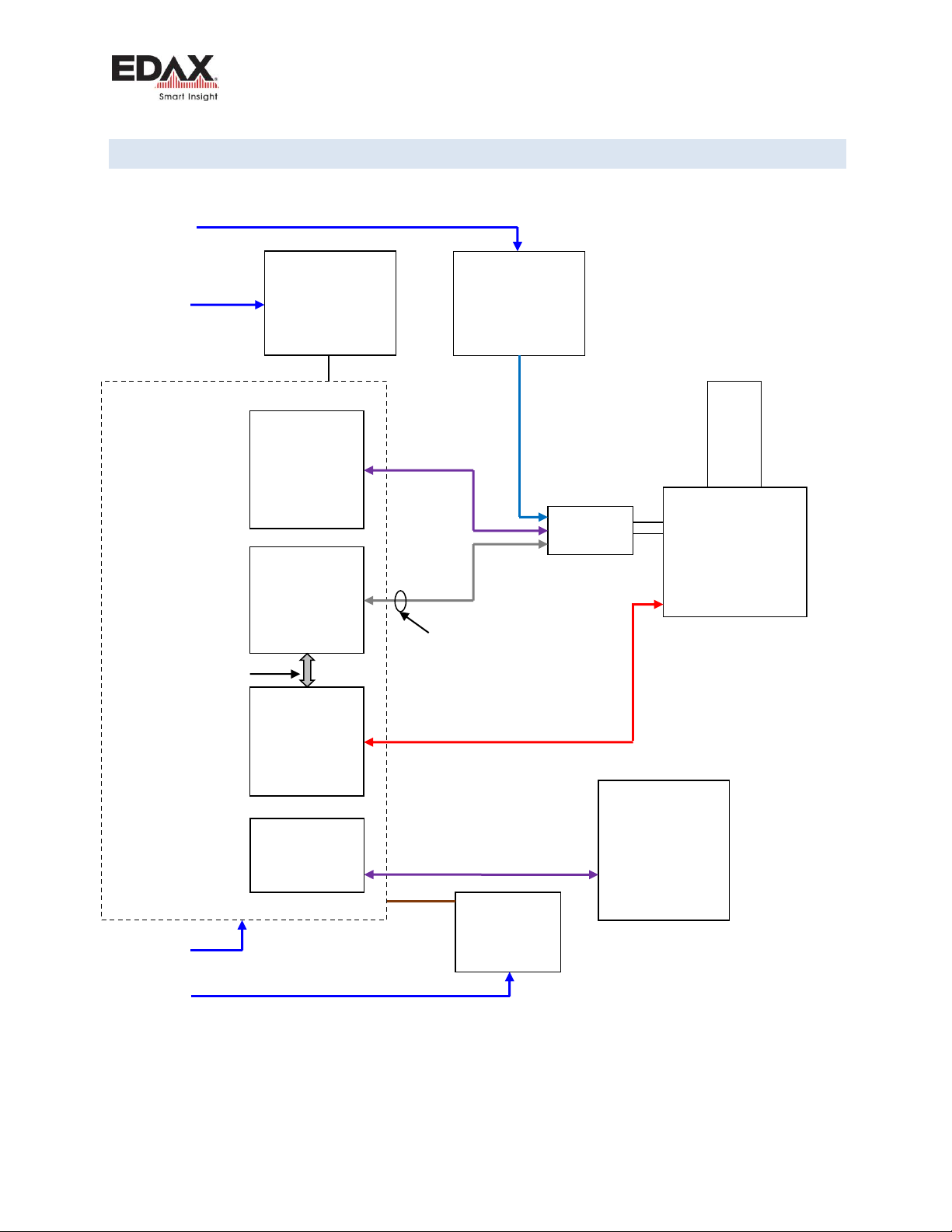
5.2 TYPICAL MICROSCOPE SYSTEM CONFIGURATION (SG-2)
Figure 7 - Typical System Connections (SG-2)
EDAX PC
Mains
Mains
Cable - 4035.008.07290
Monitor
NIC (PCIe)
2735.171.30939
IP. 192.168.0.101
SYNC (PCIe)
5335.007.28300
SG-2 (PCI)
5335.007.20000
Mains
24V
Power Supply
2735.171.31074
Microscope
Octane
IP. 192.168.0.100
NIC
IP ###.###.###.###
Microscope PC
IP ###.###.###.###
Ethernet cable
2435.072.44045R
Sync cable
4035.008.10900
Ferrite
For Column control and/or Network
Beam control cable -Microscope model dependent
4035.008.#####
24V
100-240V
100-240V
100-240V
J1
J5
Printer
(optional)
100-240V
Mains
This manual suits for next models
1
Table of contents
Other Metek UPS manuals


