Metos SF 500 User manual

BLAST FREEZER
SF
TYPE: 500, 700
Accessories
CENTRAL REFRIGERATION ATTACHMENT
Installation and Operation Manual
S/N: 56454 Rev.: 4.0
4155069, 4155076, 4135577, 4135584


13.2.2009 Rev.
1. General .......................................................................................................... 1
1.1 Symbols used in the manual .......................................................................................... 1
1.2 Symbols used on the appliance ...................................................................................... 1
1.3 Checking the relation of the appliance and the manual ................................................. 1
2. Safety .............................................................................................................. 2
2.1 Safe use of the appliance ............................................................................................... 2
2.2 Disposal of the appliance ............................................................................................... 2
3. Functional description .................................................................................. 3
3.1 Permitted use ................................................................................................................. 3
3.2 Construction .................................................................................................................. 3
4. Operation instructions ................................................................................. 4
4.1 General .......................................................................................................................... 4
4.1.1 Freezing ................................................................................................................ 4
4.2 Operation ....................................................................................................................... 4
4.2.1 Freezing ................................................................................................................ 4
4.2.2 Observe during operation ....................................................................................... 5
4.3 After use ........................................................................................................................ 5
4.3.1 Cleaning ................................................................................................................. 5
4.3.2 Service by the user ................................................................................................. 6
4.3.3 Service by authorised service personnel ................................................................ 6
5. Installation ..................................................................................................... 7
5.1 General .......................................................................................................................... 7
5.2 Transportation and storage ............................................................................................ 7
5.3 Unpacking the appliance ............................................................................................... 7
5.4 Installation ..................................................................................................................... 7
5.5 Cleaning ......................................................................................................................... 8
5.6 Electrical connections .................................................................................................... 8
5.7 First run ......................................................................................................................... 8
6. Adjustment instructions ............................................................................... 9
6.1 Setting the internal temperature and starting the manual defrost ................................. 9
7. Troubleshooting .......................................................................................... 11
8. Technical specifications ................................................................................ 13


13.2.2009 Rev. 4.0
General
1
1. General
Carefully read the instructions in this manual as they contain important information re-
garding proper, efficient and safe installation, use and maintenance of the appliance.
Keep this manual in a safe place for eventual use by other operators of the appliance.
The installation of this appliance must be carried out in accordance with the manufactur-
er’s instructions and following local regulations. The connection of the appliance to the
electric and water supply must be carried out by qualified persons only.
Persons using this appliance should be specifically trained in its operation.
Switch off the appliance in case of failure or malfunction. The periodical function checks
requested in the manual must be carried out according to the instructions. Have the appli-
ance serviced by a technically qualified person authorized by the manufacturer and using
original spare parts.
Not complying with the above may put the safety of the appliance in danger.
1.1 Symbols used in the manual
This symbol informs about a situation where a safety risk might be at hand. Given instruc-
tions are mandatory in order to prevent injury.
This symbol informs about the right way to perform in order to prevent bad results, appli-
ance damages or hazardous situations.
This symbol informs about recommendations and hints that help to get the best perform-
ance out of the appliance.
1.2 Symbols used on the appliance
This symbol on a part informs about electrical terminals behind the part. The removal of
the part must be carried out by qualified persons only.
1.3 Checking the relation of the appliance and the manual
The rating plate of the appliance indicates the serial number of the appliance. If the man-
uals are missing, it is possible to order new ones from the manufacturer or the local rep-
resentative. When ordering new manuals it is essential to quote the serial number shown
on the rating plate.

13.2.2009 Rev. 4.0
Safety
2
2. Safety
2.1 Safe use of the appliance
Please take careful note of the following instructions and warnings:
• Always unplug the cold cabinet from the power supply before moving it or doing
servicing procedures.
• Before cleaning, the cabinet shouldbe switched off. Water should not get into con-
tact with electric devices. Direct water spraying is prohibited.
• When the cold cabinet is not used for a long time, it should be unplugged from the
power supply and the interior should be cleaned and dried carefully. Doors may be
dangerous e.g. for playing children, so storing should be arranged in such a way
that it is impossible for anybody to get locked inside.
2.2 Disposal of the appliance
When the freezer is taken out of use, please contact the local authorities to make sure that
refuse collection can be done in an environmentally friendly way and according to local
legislation. Removing the door makes sure that nobody can get locked inside.
13.2.2009 Rev. 4.0
Functional description
3
3. Functional description
3.1 Permitted use
The appliance shall only be used for freezing foods and beverages. The manufacturer is
not responsible for the consequences if the appliance is used for other purposes.
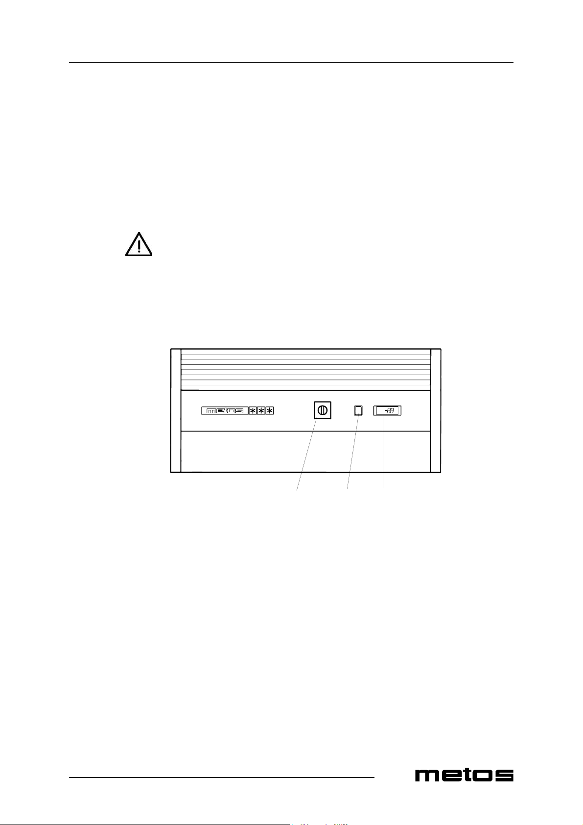
3.2 Construction
The front panel of the cabinet has the following components:
Front panel
1. Main switch
2. Temperature display / control device
3. Timer
312
13.2.2009 Rev. 4.0
Operation instructions
4
4. Operation instructions
4.1 General
4.1.1 Freezing
The performance of the blast freezer is based on efficient air circulation. The fan located
inside the cabinet rotates chilled air through air channels on the cabinet side walls. The
desired freezing time can be adjusted with the timer between 0 to 12 hours. While freezing
is in operation, the cabinet always functions at maximum output, and the thermostat and
automatic defrost are not in operation. When the preset freezing time has been reached,
the cabinet starts to function as a conventional freezer.
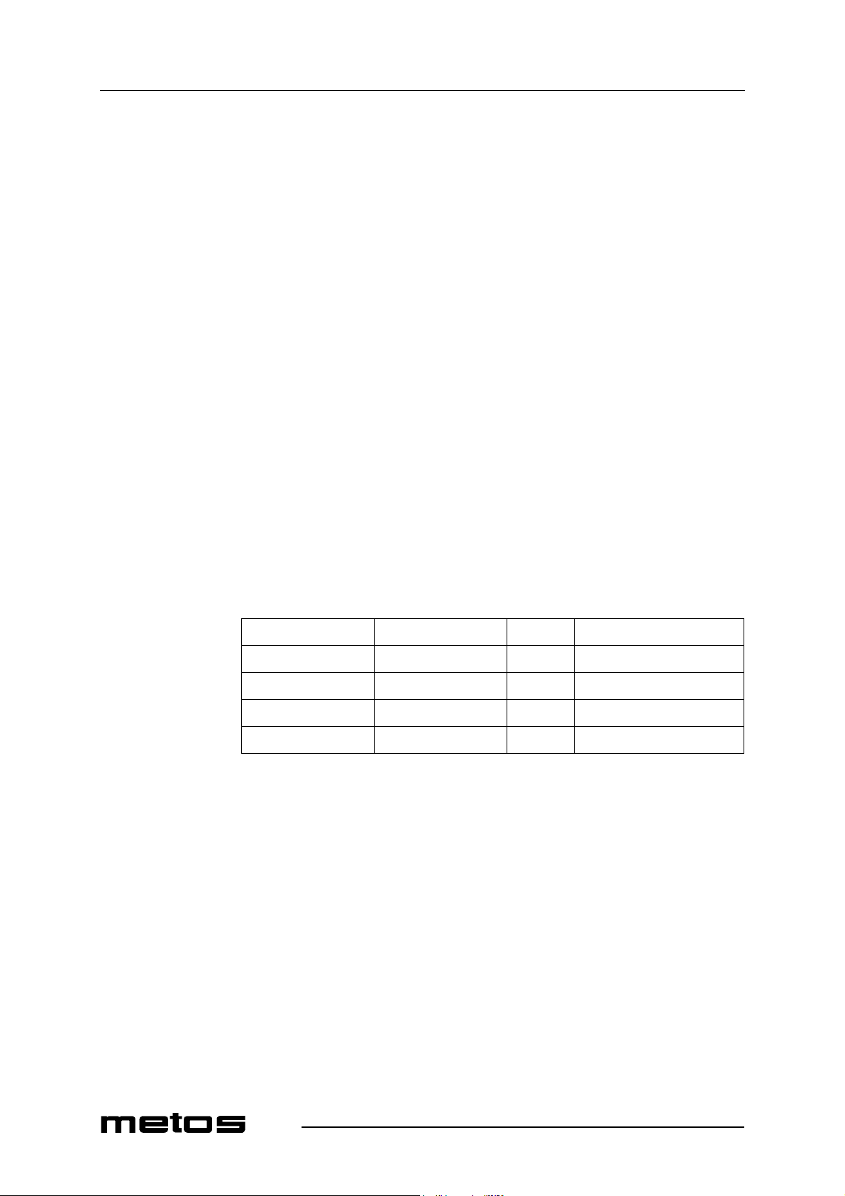
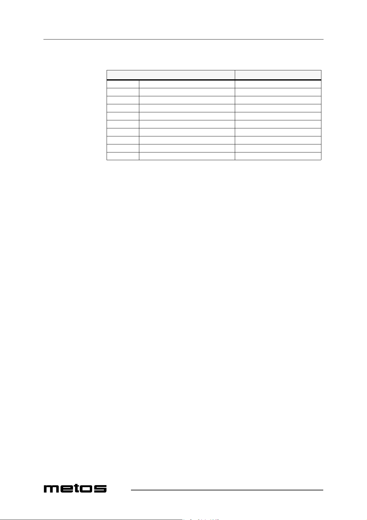
Make sure that the products are suitable for freezing. The required freezing time depends
on how fully loaded the cabinet is as well as on the properties of products and containers.
By trying various combinations you will find a suitable freezing time for each situtation.
The capacities below are indicative values assuming that the product thickness is max. 50
mm. By reducing the amount to be freezed you will reach faster freezing times.
4.2 Operation
4.2.1 Freezing
Freezing can be done as follows:
• Switch on the appliance at the main switch and wait until the cabinet temperature
falls to the correct storage temperature (factory setting –20 °C).
• Put the products to be frozen in the cabinet and close the door.
• Adjust the desired freezing time at the timer. The compressor will start.
• When the products have been frozen, they can be removed from the cabinet and
placed into appropriate storage. The blast freezer can also be used for contempo-
rary storage of frozen products while leaving the main switch on.
Cabinet type Change of temperature Time Maximum weight
SF 500 0 °°C...–18 °C 12 h 25 - 30 kg
SF 500 0 °C...–18 °C 6 h 15 kg
SF 700 0 °C...–18 °C 12 h 75 kg
SF 700 0 °C...–18 °C 6 h 30 kg
13.2.2009 Rev. 4.0
Operation instructions
5
• When the cabinet is no more used, turn the main switch off and clean and dry the
interior of the cabinet.
When especially fast freezing is required, the cabinet can be precooled using a fan. This
is done by turning the fan function on at the timer for 30 minutes before loading the cab-
inet.
4.2.2 Observe during operation
To achieve the best result with regard to product properties and energy economy please
observe the following instructions:
• Do not load the cabinet until the temperature has fallen to the preset level.
• Make sure that enough space is left for efficient air circulation between the prod-
ucts. Do not load products in touch with the walls. Place the products evenly mak-
ing full use of the cabinet interior.
• Always store products on shelves (in roll-in models on trolleys). Never load any
products on top of the bottom plate.
• Use shallow containers and small product thickess.
• Avoid opening the door during the process.
• When automatic defrost is in operation, the letters “dF” are shown on the display.
Starting the cabinet with the timer interrupts the defrost operation. If possible, wait
before starting the cabinet until the defrost cycle has terminated (the display shows
temperature).
• In case you use the cabinet for contemporary storage of products, always unload
the cabinet before freezing a new batch.
• The compressor output of the blast freezer is dimensioned for the freezing func-
tion. The products must be chilled before placing them in the cabinet. Never use
the freezer for chilling hot products.
The use of lids hinders air circulation and thus lengthens the freezing time. When the cab-
inet is only used for storage of frozen products, it is recommended to provide containers
with lids. This will reduce formation of ice on the evaporator.
4.3 After use
4.3.1 Cleaning
Always clean and dry the cabinet interior after use. When the cabinet is not in use and the
main switch has been turned off, the door can be left ajar allowing the inside humidity to
ventilate.
For cleaning the interior and the exterior, use a neutral or slightly alkaline cleaning agent.
It is recommended to occasionally clean the interior with a disinfectant. Impurities can
usually be wiped off with a damp cloth. Removing the shelves helps cleaning the interior.
Water should not get in contact with electric components. Use of a hose for cleaning the
freezer is prohibited.

13.2.2009 Rev. 4.0
Operation instructions
6
4.3.2 Service by the user
In normal use, the cabinet only requires little maintenance. The user can do the following
procedures:
• Cleaning the interior and the exterior daily or as needed.
• Cleaning the condenser at least two times per year, in frequent use more often. The
condenser grid is located on top of the cabinet. Before cleaning, switch off the cab-
inet at the main switch and unplug the cable from the power supply. Use either a
vacuum cleaner or a soft brush. When brushing the condenser, be careful not to
damage the aluminium grid.
4.3.3 Service by authorised service personnel
All other maintenance not mentioned in the chapter above should be done by authorised
service personnel. The need for maintenance highly depends on external conditions and
how frequently the appliance is used.
Contact your local Metos-dealer to get additional information. Identification of the appli-
ance helps when ordering spare parts, service or repair. The type and serial number of the
appliance have been marked on the type plate inside the cabinet.
13.2.2009 Rev. 4.0
Installation
7
5. Installation
5.1 General
To guarantee trouble-free operation and effective energy economy, the cold cabinet
should not be installed adjacent to heat sources. Do not place the cabinet near ovens, bain
maries etc. The cabinet is designed for operation in room temperaturesof +10ºC to +30ºC.
All cold appliances generate heat while they are running. For this reason they should only
be installed in places with adequate ventilation.
5.2 Transportation and storage
If possible, do not unpack the cabinet until it has been moved near the installation place.
Avoid tilting.
If the cabinet has been tilted sharply before start-up, it is necessary to wait for at least 15
minutes before switching it on. This makes sure that the compressor oil sets into place.
The cabinet should always be stored indoors.
If the cabinet has been stored in a place where the temperature of the cooling unit has fall-
en below 0 ºC, it should not be switched on until the temperature of the cooling unit is at
least +10 ºC. Switching on the cold cabinet with too low temperature may cause malfunc-
tion of the compressor.
5.3 Unpacking the appliance
Unpack the cabinet and remove the white plastic film protecting the shelves.
5.4 Installation
Move the cabinet to its place.
When lifting the cabinet with the help of a mechanical device, make sure that the base
construction is not damaged.
Adjust the cabinet horizontally with adjustable legs. Use a bubble when necessary. Rec-
ommended deviation from the horizontal plane is +-0,5 degrees. All legs shouldtouch the
floor. This guarantees that the doors work properly.

13.2.2009 Rev. 4.0
Installation
8
5.5 Cleaning
Wipe clean and dry the interior, the shelves and the exterior before use. For cleaning, use
a neutral or slightly alkaline cleaning agent.
5.6 Electrical connections
After the appliance has been three hours in place, it can be started. Connect the appliance
to the power supply with an earthed socket. For making the connection, a socket protected
with a 16 A fuse has to be provided. Check that the local power supply has the same volt-
age as the cabinet.
5.7 First run
Switch on the appliance with the main switch. Check that the internal temperature of the
cabinet reaches the value preset in the factory (-20 °) and that the timer functions normal-
ly.

13.2.2009 Rev. 4.0
Adjustment instructions
9
6. Adjustment instructions
6.1 Setting the internal temperature and starting the manual defrost
The microprocessor-based control unit contains a series of parameters to control the cab-
inet functions. Each control unit has been pre-programmed in the factory. The user can
carry out two programming functions: setting the temperature and starting a manual de-
frost cycle.
Thermostat EKC 102D
The display of the control unit normally shows the air temperature inside the cabinet.
The set value (usually -20ºC) can be displayed by briefly pressing the middle button (2).
To increase the value, press the upper button (1). To decrease the value, press the lower
button (3). The value will be saved automatically. Within approx. 15 seconds, the display
will show the internal temperature of the cabinet.
To start a manual defrost cycle, press and hold down the button (3) for about 5 seconds.
LED (5) is on and (-d-) is shown on the display during the defrost cycle. When the defrost
cycle is over and the set value has been reached, the display will show the internal tem-
perature.
LED (4) is on when the compressor is running.
LED (6) is on when the evaporator fan is running.
With the setting of -20ºC, the temperature of products inside the cabinet is between
-18...-20ºC. Defrosting is carried out automatically every six hours. LED (5) is on when
an automatic defrost cycle is in progress.
13.2.2009 Rev. 4.0
Adjustment instructions
10
Fault messages (in case the alarms are enabled). If an alarm occurs, the LEDs will flash
on the display. Press the upper button (1) to display the alarm codes.
Alarm code Action
A1 High temperature alarm
A2 Low temperature alarm
A4 Door alarm
A15 Alarm signal (DI input)
A45 Standby mode (r12 or DI input)
A59 Cleaning (DI input)
E1 Fault in controller
E27 Sensor error on S5
E29 Sensor error on Sair
E30 Sensor error on Saux
7. Troubleshooting
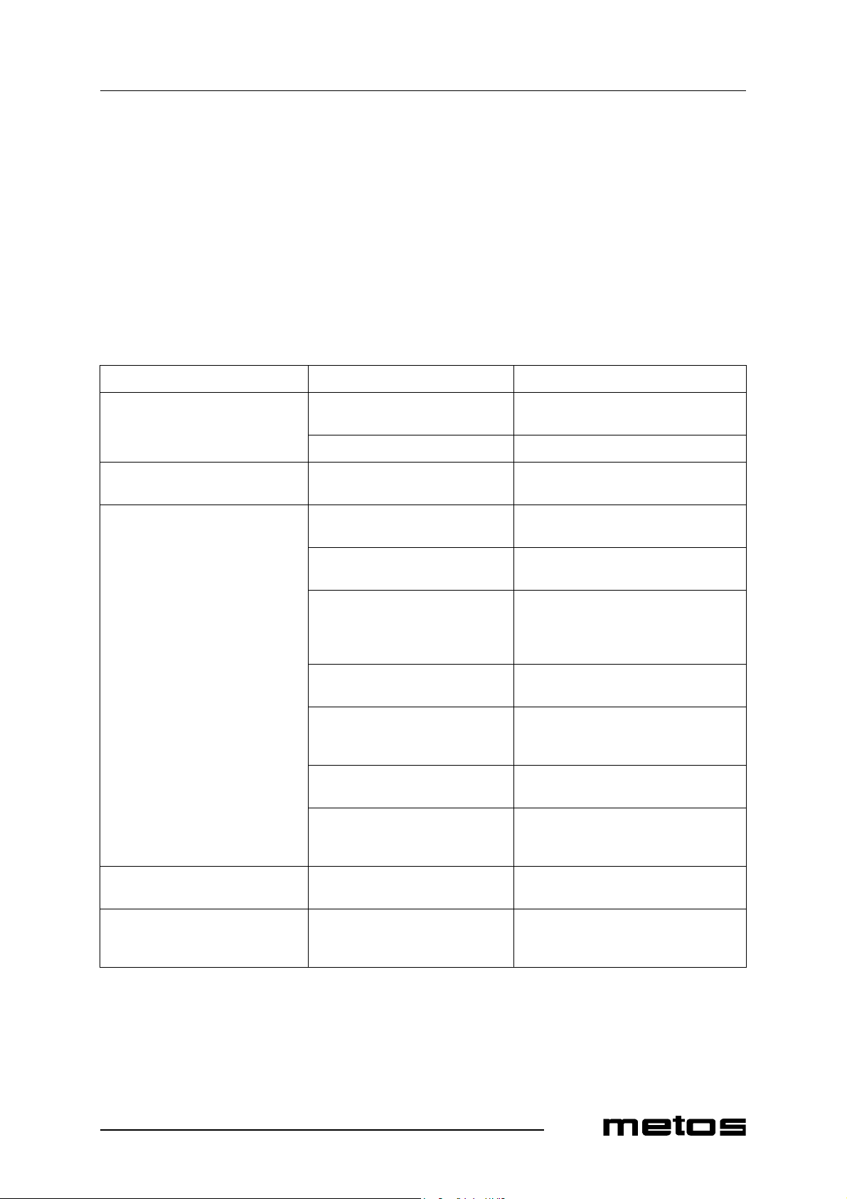
In case of malfunction, review the following list and check if it is possible to put the ap-
pliance in order without a service call. In all enquiries, please contact the nearest Metos-
service.
PROBLEM POSSIBLE CAUSE ACTION
The appliance does not start even if
the main switch is turned on (indica-
tor light is not lit)
Electrical cable is not properly
plugged into the socket. Set the cable properly
Fuse has blown Change the fuse
The main switch is working normal-
ly, but the fan does not start The door is open or the door switch is
damaged Close the door and check that the door
switch can move freely
The compressor is running but the
temperature does not fall to the set
value. The product temperature does
not fall within the normal chilling
time.
Condenser is covered by dust Clean the condenser according to instruc-
tions
Prevented air circulation beside the
condenser Ensure appropriate air circulation. Check
the cabinet surroundings.
Ambient temperature is too high Make sure that the appliance has not been
placed near a heat source. Move the cabi-
net to a cooler place and arrange ventila-
tion if necessary.
Door switch does not work Make sure that the door switch can move
freely.
Evaporator is covered by ice Start manual defrost. If the appliance does
not work normally after the defrost cycle,
contact service personnel.
Cabinet is overloaded or product
thickness is too great Reduce the amount of products and/or re-
arrange them
Products have been placed so that
they hinder air circulation inside the
cabinet
Arrangetheproductssothatair circulation
is free
While running, the cabinet makes ex-
ceptionally loud noise The cabinet is not firmly in place Position the cabinet with adjustable legs
horizontally so that all legs touch the floor
The cabinet’s internal temperature is
higher than normal, the compressor is
not running
Defrost in operation: LED (5) is on,
“d” is shown on the display Wait until the defrost cycle is complete.
Check the temperature after that.


13.2.2009 Rev. 4.0
Technical specifications
13
8. Technical specifications
Refrigeration circuit diagram
Wiring diagram SF; 500
Wiring diagram SF; 700
Wiring diagram SF; 500, 700; CCU
Installation drawing 500
Installation drawing 700

Refrigeration circuit diagram

13.2.2009 Rev. 4.0
Technical specifications
15
Wiring diagram SF; 500
1 Condensing unit Kylaggregat Kylmäkompressori
2 Electronic control device Elektronisk styrenhet Elektroninen ohjausyksikkö
3 Defrost heat element 230V Avfrostningselement 230V Sulatusvastus 230V
4 Door switch Dörrbrytare växlande Ovikytkin
5 Fan for condenser Förångarfläkt Höyrystimen puhallin
6 Light 230V Belysning 230V Valaisin 230V
7 Switch Brytare Kytkin
8 Discharge heat element 230V Avloppsvärme 230V Lämpölanka (poistoputki) 230V
9 Gasket heat element 230V Karmvärme 230V Lämmitysvastus (ovitiiviste) 230V
10 Defrost water heat element 230V Tövattenelement 230V Vastus (haihdutus) 230V
11 Terminal block Kopplingsplint Liitinrima
12 Manual timer 4 h Manuell timer 4 h Manuaaliajastin 4 h
15 Probe for defrost Sensor avfrostning Anturi sulatukselle
16 Probe for thermostat Sensor temperaturvisning Anturi termostaatille

13.2.2009 Rev. 4.0
Technical specifications
16
Wiring diagram SF; 700
1 Condensing unit Kylaggregat Kylmäkompressori
2 Electronic control device Elektronisk styrenhet Elektroninen ohjausyksikkö
3 Defrost heat element 230V Avfrostningselement 230V Sulatusvastus 230V
4 Door switch Dörrbrytare växlande Ovikytkin
5 Fan for condenser Förångarfläkt Höyrystimen puhallin
6 Light 230V Belysning 230V Valaisin 230V
7 Switch Brytare Kytkin
8 Discharge heat element 230V Avloppsvärme 230V Lämpölanka (poistoputki) 230V
9 Gasket heat element 230V Karmvärme 230V Lämmitysvastus (ovitiiviste) 230V
10 Defrost water heat element 230V Tövattenelement 230V Vastus (haihdutus) 230V
11 Terminal block Kopplingsplint Liitinrima
12 Manual timer 4 h Manuell timer 4 h Manuaaliajastin 4 h
13 Relay for start delay Startfördröjningsrelä Käynnistyksen viiverele
15 Probe for defrost Sensor avfrostning Anturi sulatukselle
16 Probe for thermostat Sensor temperaturvisning Anturi termostaatille
This manual suits for next models
1
Table of contents
Other Metos Freezer manuals


Popular Freezer manuals by other brands

Baumatic
Baumatic BRZ600.5 user manual

Miele
Miele FN 9752 i OPERATING AND INSTALLATION Manual

VOX electronics
VOX electronics VF-3200 operating instructions

Fisher & Paykel
Fisher & Paykel E210 Service manual

Electrolux
Electrolux LUT5NF28U1 user manual

Frigidaire
Frigidaire FC 100 OPERATING AND INSTALLATION Manual


