Metos E-PRO User manual

Blast Chiller - Shock Freezer
E-PRO
4240338, 4240339, 4040340, 4040341, 4040342, 4040343, 4040344, 4040345, 4040346, 4040347
Original instructions
+3°C
-18°C
start
stop
-
+
set
L1
L2 L3
RF50C00064 REV. 02 - 11/2022
Installation- and user manual

Rev. 02 - 11/2022 2
INSTALLATION SECTION
(reserved to skilled and authorised technicians)
SAFETY INSTRUCTIONS ............................................ 5
INSTALLATION............................................................ 8
BLAST CHILLER TECHNICAL DATA ........................... 64

Rev. 01 - 11/2022
3
This manual furnishes all necessary information
for the correct installation of the device operat-
ed by skilled personnel.
Read the instructions carefully before performing any
operations, as they provide essential indications con-
cerning the safety of the device.

Rev. 01 - 11/2022
5
• Read this manual carefully before in-
stalling and servicing the device and
keep it for any further future consul-
tation by the various operators.
•The manufacturer cannot be held liable for any
use of the device in contrast with the indications
provided in this manual. Remember that any
type of installation or maintenance different to
that indicated in the manual can cause damage,
injuries or fatal accidents.
•Unauthorised actions, tampering or modifica-
tions that do not follow the information provided
in this manual can cause damage, injuries or fatal
accidents and shall invalidate the warranty.
•Installation and special maintenance operations
must be performed by skilled and authorised
technicians, with good knowledge of the refrig-
erating and electrical systems, according to the
legal provisions in force in the country of use and
in compliance with standards concerning the
systems and workplace safety.
•Make sure the mains voltage and the frequency
correspond to those specified in the rating plate
before connecting the device to the electrical
mains.
•Disconnect the device from the mains before any
cleaning or maintenance (turn the main switch
to OFF and disconnect the plug).
•THE MACHINE HAS NOT BEEN DESIGNED TO BE
INSTALLED IN AN EXPLOSIVE ATMOSPHERE. Do
not keep explosive substances, such as pressur-
ised containers with flammable propellants in
this appliance.
•Before installation, please check:
- that the areas in which the machine will be in-
stalled are suitable for food preparation;
- that the systems comply with the legal provi-
sions in force in the country of use and meet
the specifications on the serial number plate;
- that a circuit breaker with high sensitivity (30
mA) is installed, to which the machine must
be connected;
- that a point of connection to the water mains
is near the device;
- that a socket with a suitable ground connec-
tion for the country of use is located near the
device;
- the planarity of the device support area, espe-
cially if it is assembled on wheels.
• During device installation:
- transit or permanence near the work area by
individuals not assigned to device installation
is prohibited;
- use the personal protection equipment (e.g.
gloves, safety footwear, etc...);
- work according to workplace safety regula-
tions (e.g. do not approach electrical parts
with wet hands or barefoot, etc...).
•ORIGINAL SPARE PARTS ARE RECOMMENDED.
The manufacturer denies all liability for the use of
non original spare parts.
•Given that packaging materials may be poten-
tially hazardous, they must be kept out of reach
of children or animals and correctly disposed of
according to the local standards.
•The device is shipped after passing inspections:
visual, electric and functional.
SAFETY INSTRUCTIONS
The manufacturer cannot be held liable for unintended device
use. Original document language: Italian. The manufacturer is
not liable for any transcription or translation errors. It is forbidden
to reproduce this manual, even partially.

Rev. 02 - 11/2022 8
OK
EXPRESS
MAX 200 cm
A
B
C
INSTALLATION
Fig. 2 Fig. 3
Fig. 4
Fig. 5
Fig. 1
Abb. 4
Abb. 1
Abb. 2 Abb. 3
Abb. 5

Rev. 01 - 11/2022
9
min.
5 cm
min.
50 cm
min.
5 cm
air gap
min
25 mm
1”
max 200 cm
min 4°
INSTALLATION
Fig. 6 Fig. 7
Fig. 8
Fig. 9
Fig. 10
Abb. 6 Abb. 7
Abb. 8
Abb. 9
Abb. 10
1 PH
monofase - single phase - monophasé -
einphasig - monofásico - одна фаза
scarico vano
compartment drain
compartiment évacuation
Schachtablass
descarga de compartimiento
слив отсека
ontlading ruimte van de motor

Rev. 02 - 11/2022 12
Characteristics of the installation area
Install the device in areas:
- compliant with industrial food handling;
- with adequate ventilation;
-prepared with electrical and plumbing systems compliant with
the legal provisions in force in the country of use and according
to the workplace safety requirements in the country of use;
- with temperatures from +15° to +43°C;
- that are sheltered against the elements;
- with flooring able to support the device at full load.
If the device is assembled on wheels (kit sold separately), it can-
not be levelled. Therefore the surface must be perfectly horizon-
tal, flat and completely smooth.
Protective lm removal
Fig. 5 If the machine is intact, remove the protective film slowly.
Any glue residue can be removed with a proper sol-
vent. Do not use tools or abrasive or strong detergents
that might ruin the surfaces.
The removed protective films are potentially danger-
ous for children and animals.
DO NOT LEAVE THEM UN
ATTENDED IN THE INSTALLATION AREA AND CORRECT
LY DISPOSE OF THEM IN ACCORDANCE WITH LOCAL
STANDARDS.
Positioning
The machines must be positioned on the ground only, on floors:
- that are not sensitive to heat or flammables;
- perfectly levelled;
- with a regular surface and completely smooth;
- that can support the device at full load.
Fig. 6 Keep the illustrated minimum clearances around the de-
vice: this will facilitate connections to utilities and maintenance.
Fig. 7
Always check for perfect levelling: if this is not the case,
rotate the feet until achieved.
DO NOT INSTALL THE DEVICE:
-NEAR OTHER MACHINES THAT REACH HIGH TEM
PERATURES E.G. OVENS OR FRYERS;
-NEAR WALLS OR FURNITURE THAT IS EITHER FLAM
MABLE OR SENSITIVE TO HEAT.
Only use the manufacturer’s wheel kit to make the de-
vice movable. For assembly, if necessary, read the in-
structions supplied with the kit.
Spacer installation
The devices require ventilation at the back, where the vents and
refrigerating unit are found.
Therefore, do not place them against the wall but keep them ap-
proximately 5 cm away.
Fig. 8 In order to prevent accidental movements from shifting
the device too close to the wall, install the provided spacers on
the back of the device (especially if the device is assembled on
wheels). Use supplied spacers and screws only.
Drawings on page 8
Product transport, handling
Warning markings are printed on the packaging. They indicate
the limitations that must be observed to ensure safe device load-
ing, unloading and transport.
Fig. 1 Device transport and handling must be done exclusively
as follows:
-keep the packaging in the vertical position, as per the indications
printed on it (this precaution is necessary to prevent the oil con-
tained in the compressor from circulating, which may damage
the valves and cause problems when starting the motor);
-use suitable handling means. Do not handle the goods by hand.
If hoisting systems are used, such as forklifts or pallet jacks, the
weight must be carefully balanced.
The packaging usually consists in polystyrene and stretch film on
a wooden pallet, which is secured to the bottom of the device for
safer transport and handling.
The manufacturer cannot be held liable for problems due to
transport in conditions other than those previously specified.
PAY PARTICULAR ATTENTION TO THE PACKAGING IN
CLINATION DURING TRANSPORT SINCE THE DEVICE
BARYCENTRE DOES NOT CORRESPOND TO ITS GE
OMETRICAL CENTRE.
Stacking limits
The devices, regardless of the model, CANNOT be stacked during
transport or during storage.
Device check
Fig. 2 We recommend, after removing the packaging, you
check device integrity and make sure it was not damaged during
transport. If damage or anomalies are found, do not install the
device and promptly inform the carrier. In any case, damaged
devices cannot be returned to the manufacturer without prior
notice and without prior written authorisation.
Fig. 3 AFTER UNPACKING, WHEN MOVING THE DE
VICE DO NOT PUSH IT OR PULL IT IN ORDER TO
AVOID THE RISK OF OVERTURNING OR DAMAGING
SOME PARTS FOR EXAMPLE THE FEET.
NEVER TILT THE DEVICE FROM THE DOOR SIDE.
Systems preparation
Fig. 4 Systems must comply with the legal provisions in force
in the country of use and meet the specifications on the serial
number plate.
There must be:
-A: a circuit breaker with high sensitivity (30 mA);
-B: a point of connection to the power mains;
-C: a point of discharge (optional).
Please see the specific chapters for their specifications
(for example, the chapter “Electrical connection”).
INSTALLATION
Rev. 01 - 11/2022
13
Electrical connections
THE CONNECTION TO THE ELECTRICAL MAINS AND
OTHER SUPPLIES MUST COMPLY WITH THE LEGAL
PROVISIONS IN FORCE IN THE COUNTRY OF INSTAL
LATION AND MUST BE PERFORMED BY QUALIFIED PERSONNEL
AUTHORISED BY THE MANUFACTURER.
In order to avoid any risks, damaged power supply ca-
bles must be replaced by the Manufacturer, by an ap-
proved technical support centre, or in any case by an
individual with similar qualifications.
Before connecting the device to the mains:
-read the safety instructions provided at the beginning of this
manual;
-make sure the mains voltage and frequency correspond to
those indicated in the device serial number plate. A rated volt-
age variation of +/-10% is accepted.
THE DEVICE MUST BE CONNECTED TO AN EFFICIENT
GROUND SOCKET .
THE DEVICE MUST BE INCLUDED IN AN EQUIPOTEN
TIAL SYSTEM COMPLIANT WITH THE LEGAL PROVI
SIONS IN FORCE YELLOW GREEN CONDUCTOR
WITH A MAXIMUM SECTION OF 10 MM2 IEC EN
60335242:200309 STANDARD. THIS CONNECTION MUST BE
MADE BETWEEN VARIOUS DEVICES WITH THE TERMINAL
MARKED WITH THE EQUIPOTENTIAL SYMBOL .
For mains connections, use a circuit breaker with manual reset
high sensitivity (30 mA), with adequate power that permits com-
plete cut-off in over voltage category III conditions, in order to
protect the device against over voltages or short circuits.
For the sizing of the protection device, please refer to the techni-
cal data table at the end of the manual.
Fig. 9 The single-phase appliances leave the factory with the
power cable and an Unel plug already installed on the terminal
block: it is not allowed to make any other type of electrical con-
nection and no dimensional modification of the cable other than
its lengthening, replacing it with one having the same character-
istics as the original one (rubber type, section, etc.).
Plumbing connections
THE DRAIN MUST COMPLY WITH THE LEGAL PROVI
SIONS IN FORCE IN THE COUNTRY OF INSTALLATION
AND MUST BE PERFORMED BY QUALIFIED PERSON
NEL AUTHORISED BY THE MANUFACTURER.
Outlet water
Cleansing water is collected in a tank which is under the machine.
Fig. 10 We recommend you connect the drain to a flexible hose
of maximum length 200 cm (not supplied) and lead it to a grate
in the floor or wall drain pipe, to avoid empting the tank too fre-
quently.
The drain pipe must have the following characteristics:
- is fitted with a trap;
- has a minimum inclination of 4%;
- has an air gap* of at least 25 mm;
- does not have clamps;
- has a diameter no less than that of the drain pipe coupling.

Rev. 02 - 11/2022 18
Instructions manual available in an alternative format
QR CODE
QR CODE SCAN
1
2PDF
USER MANUAL
WIRING
DIAGRAMS
Maximum storage values: 60°C
Maximum transport values: 60°C
Maximum values for the installation environment: 43°C
Do not stack or store lying down.
WOOD
POLYSTYRENE
PAPER
NSTALLATION

Congratulations on having purchased our equipment!
Work is simpler due to the intuitive user interface graphics designed to simplify access to functions, which
allow immediate identification and promote interaction between the user and the device.
A concentration of technology in a single machine that allows you to perform different and complemen-
tary activities for best efficiency in the kitchen: this way you’ll be immediately operative, without having to
run any complex procedures.
This manual furnishes all necessary information nec-essary for correct use of the device and appropriate
maintenance.
Read the instructions carefully before performing any operations, as they provide essential indications
con-cerning the safety of the device.

USER SECTION
(reserved to user)
SAFETY INSTRUCTIONS ............................................... 24
INFORMATION............................................................... 30
USE .............................................................................. 38
MAINTENANCE.............................................................. 46
ALARMS ......................................................................... 54

Rev. 02 - 11/2022 24
• Read this manual carefully before in-
stalling and servicing the device and
keep it for any further future consul-
tation by the various operators.
•Use and cleaning other than the types indicat-
ed and foreseen in this booklet are considered
improper and can cause damage, injuries or fatal
accidents, shall invalidate the warranty and re-
lease the manufacturer of any liability.
•Use is solely reserved to trained and authorised
personnel who attend periodic refresher courses.
•The appliance can be used by children under the
age of 8 and by people with reduced physical,
sensory or mental abilities, or without experience
or the necessary knowledge, as long as they are
supervised and after they have received instruc-
tions relating to the safe use of the appliance and
an understanding of the inherent dangers. Chil-
dren must not play with the appliance. Cleaning
and maintenance intended to be carried out by
the user must not be carried out by unsupervised
children.
•Keep away from electrical parts with wet hands
or bare feet.
•It is strictly prohibited to tamper with or remove
the adopted safety devices (protection grates,
hazard stickers, etc.). The manufacturer cannot be
held liable if these instructions are not heeded.
•Do not insert screwdrivers or other objects be-
tween guards (fan guards, evaporator guards,
etc.).
•For good compressor and evaporator unit opera-
tions, never obstruct the air vents.
•In the event of fire, do not use water. Install a CO2
(carbon dioxide) extinguisher and cool the mo-
tor compartment as quickly as possible.
Correct use of equipment
•This equipment is considered an agri-food ma-
chine (EC Regulation no. 1935/2004), intended
to process food products in industrial and pro-
fessional kitchens. It is not suited to store phar-
maceutical, chemical or any other non-food
products.
• Specifically:
-Blast chillers (+90/+3°C) (+90/-18°C): suited to
rapidly lower food temperature to keep senso-
ry properties unaltered.
•The following instructions must be followed for
best performance of the equipment:
-Do not place hot food (except for chiller func-
tions), uncovered liquids, live animals, various
objects or corrosive products in the equipment.
-Package or otherwise protect foods especially if
they contain aromas or spices.
-Arrange foodstuffs inside the equipment in such
a way as not to limit air circulation, avoiding
placing paper, cardboard, cutting boards, etc.,
that can hinder the flow of air on the racks.
-Avoid frequent and prolonged door opening as
much as possible.
-If the door was opened and closed again, wait a
few seconds before re-opening it.
-Gradually arrange the food starting from the
bottom up; vice versa, remove the food start-
ing from top to bottom. The maximum load
(evenly distributed) per tray or grill is equal to
20 kg (GN 1/1) or 35 kg (GN 2/1).
•Refrigerator equipment has been constructed
and designed using suitable techniques to guar-
antee user health and safety and does not have
any hazardous corners, sharp surfaces or protrud-
ing elements. Its stability is also guaranteed with
the doors open, however, hanging on doors is
prohibited.
•Failure to follow these instructions may cause
damage and injuries, even fatal, and shall inval-
idate the warranty.
In the event of equipment malfunctions...
•If the equipment does not work or functional
or structural alterations are noted, disconnect it
from the power and water mains and contact
a service centre authorised by the manufactur-
er without attempting to repair it on your own.
Original spare parts are recommended.The man-
ufacturer shall not be held liable for the use of
non original spare parts.
•To ensure that the device is in perfect use and
safety conditions, we recommend you have it
maintained and serviced by an authorised ser-
vice centre at least once a year.
SAFETY INSTRUCTIONS

Rev. 01 - 11/2022
25
Risks associated with equipment
use
•RISKS DUE TO MOVEMENTS ON WHEELS: if the
equipment is installed on wheels, take care dur-
ing movements not to suddenly push the equip-
ment, thus preventing it from overturning and
being damaged. Also look out for any roughness
on the sliding surface. Equipment with wheels
cannot be levelled, therefore make sure the
support surface is perfectly horizontal and flat.
Always lock the wheels with the specific stops.
•RISKS DUE TO MOBILE ELEMENTS: the only mo-
bile element is the fan, which however does not
constitute a risk since it is protected by a protec-
tion grate secured with screws.
•RISKS DUE TO LOW/HIGH TEMPERATURES: stick-
ers marked “TEMPERATURE HAZARD” have been
affixed near areas with low/high temperature
risks.
•RISKS DUE TO ELECTRICITY: risks of electrical na-
ture have been resolved by designing electrical
systems as per regulation CEI EN 60335-1. Spe-
cific stickers marked “high voltage” identify areas
with electrical hazards.

Rev. 02 - 11/2022 30
OK
Fig. 11 Fig. 12
Abb. 11 Abb. 12
Rev. 02 - 11/2022 32
-perform routine maintenance as indicated in the specific section;
+
For further information on how to remove the lter, see chap-
ter Vent cleaning on page 47.
How to use the needle probe
Fig. 12
The needle probe, during chilling, reads the tempera-
ture at the food “core”: when it reaches the value set by the user or
default value, it means the food is chilled (
Chilling
function).
The
needle probe is fully inserted in the food to be chilled: make sure
its tip reaches the food “core”, meaning the most internal point,
without exiting.
Be careful not to insert it in very fatty points and near bones.
In case of very thin food products, insert the probe parallel to the
support surface.
Always keep the probe clean and sanitised.
HANDLE THE PROBE WITH CARE INSOFAR AS IT IS
VERY SHARP.
+
The probe can be heated to facilitate removal from frozen
foods, see page 39.
Drawings on page 30
What does a blast chiller do?
A blast chiller is a device that quickly lowers the temperature of
the introduced food, whether fresh or cooked.
Fresh or just cooked food has the best sensory qualities and fla-
vour; however, if not eaten immediately, it loses its initial qualita-
tive properties and is subject to the proliferation of micro-organ-
isms, which are potentially harmfuly to humans.
Positive Chilling is used when food is not eaten within two
hours of its preparation, reducing the product temperature to
+3°C at the core within 90 minutes. Subsequently, the prod-
uct must be stored in a refrigerator at a temperature between
0/+3°C where it can be kept for up to 5 days.
Negative Chilling is used to keep all the sensory properties of
the food intact. The chiller reduces the product temperature un-
til reaching -18° C at its core. Subsequently, the product must be
stored in a freezer at a constant temperature of -20 degrees and
can even be eaten after 3/18 months, according to the product,
provided the cold chain regulations are met.
Storage is the next step in the blast chilling cycle, in which the
food product is maintained at a certain temperature in order to
preserve its cooling or freezing.
It is divided into:
Positive storage, in the case of cooling;
Negative storage, in the case of freezing.
Normal refrigerators and freezers, unlike a blast chiller, are unable
to rapidly lower the initial temperature of the product, which is
therefore damaged in terms of its sensory properties and flavour.
Correctly loading the equipment
Food should be placed in a single layer in containers:
- that are uncovered;
- that are food-safe;
- that are resistant to the temperatures reached by chilling;
- that have low edges (maximum 4.5 cm).
Containers should be evenly placed inside the cell.
Correct container placement will allow free air circulation in the
cell: avoid obstructing the air vents and overloading the equip-
ment beyond the admissible limits.
Achieving better results and working in
safe conditions
-Fig. 11 Keep the motor compartment air vents free of objects
and remove dust;
-periodically clean and replace the filter behind the motor com-
partment air vents:
+
For further information on how to remove the lter, see chap-
ter Vent cleaning on page 47.
-arrange food to be chilled or cooked as explained in the previ-
ous chapter;
- accurately close the doors during each work cycle;
- always keep the defrost water drain hole free;
- avoid opening doors during positive/negative chilling;
INFORMATION

Rev. 02 - 11/2022 36
+3°C
-18°C
start
stop
-
+
set
L1
L2 L3
L1
L2
L3
SET
DOWN
x4 sec.
UP
x4
SEL
x4 sec.
DOWN+UP
+x4 sec.
LED with decimal point
function to display the
time.
LED with function of
indicating the negative
blast chilling cycle
selected
steady on: LED which has
the function of indicating
the blast chilling cycle in
progress;
flashing: LED which has
the function of indicating
the storage phase in
progress
DESCRIPTION
Blast chiller start/stop operation
and confirmation
Slow decrease of the value and
buzzer switch off
During a program it displays the
cell probe temperature
Fast decrease of the value and
defrost activation
Slow increase of the value and cell
temperature display
Fast increase of the value and load
activation on the auxiliary output
(UV lamp for sterilization, needle
probe heater or auxiliary condens-
er fan)
Positive/negative alternate
program selection
Display of the elapsed time from
the start of the blast chilling cycle
or the duration of the blast chilling
cycle until the key is released
Stand-by enable
To access the configuration param-
eters press the DOWN and UP keys
simultaneously for 4 seconds
(only with blast chiller in stop phase
or if there are no programs in pro-
gress).
Short press
Short press
Short press
Short press
Continuous press
Long press
Long press
Long press
Long press
USE

Rev. 02 - 11/2022 40
Switch on
When the display switches on it performs a lamp-test (flashing of
all segments and dots for 5 seconds).
When switched on for the first time, the display is in stand-by mode
(three horizontal dashes“---”are shown on the display, one for each
digit). The next time it is switched on, or when the power supply
is restored, the blast chiller status varies depending on its status
befo
re the power supply failure.
If there is no program running, activate standby mode by press-
ing and holding SEL for 4 seconds.
Important information
The display shows programs for managing the following blast
chiller functions:
positive blast chilling or cooling (automatic or manual),
negative blast chilling or freezing (automatic or manual)
+
For automatic programs, the reference value is the tem-
perature detected by the needle probe.
For manual programs, the reference value is the time.
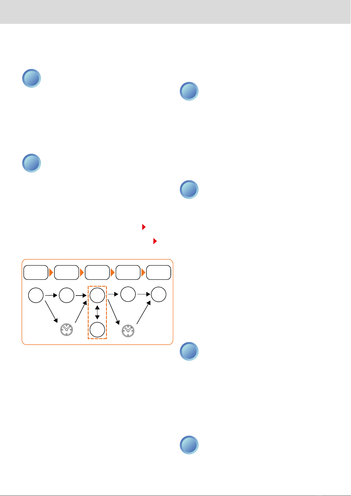
Both the automatic program and the manual program include
a blast chilling cycle, automatically followed by a storage phase,
which is positive or negative depending on the cycle chosen.
At the end of the blast chilling cycle, when the storage phase
starts automatically, a buzzer sounds intermittently (this can be
modified by the user under parameter P 0).
To silence the buzzer in advance, press the DOWN key.
During the execution of a program:
-the LED L2 is off if a positive blast chilling cycle was selected,
or is on if a negative blast chilling cycle was selected;
-the L3 LED is on during the blast chilling cycle and flashing
during the storage phase;
-pressing the UP key determines the display of the temperature
measured by the cell probe for a duration of 5 seconds;
-pressing and holding the SET key determines, until the key is
released, the display of the time elapsed since the start of the
blast chilling cycle if the blast chilling cycle is still in progress,
the duration of the previous blast chilling cycle if the storage
phase is in progress.
At the end of a program, before starting the next program, the
display shows the data relative to the last program run.
Automatic program
To select and start an automatic program (Fig. 8 on page 18), pro-
ceed as described below:
-Press the SEL key until the display shows the positive blast
chilling cycle (default +3°C - P13 parameter) or negative
blast chilling cycle (default -18 °C - P14 parameter).
-
+
The repeated pressing of the SEL key causes the display
to alternately flash between the value set for the posi-
tive blast chilling cycle and the value set for the nega-
tive blast chilling cycle.
-Wait 5 seconds or press the SET key to confirm (the tempera-
ture display becomes fixed).
-Press the SET key to start the program: during the execution
of an automatic program the display shows the temperature
measured by the needle probe.
+
The temperature parameters can be modified by the
User.
SEL SET
attendere
5 sec
SET
SELEZIONE
PROGRAMMA
CONFERMA
PROGRAMMA
AVVIO
PROGRAMMA
SEL SET
wait
5 sec
SET
PROGRAM
SELECTION
PROGRAM
CONFIRMING
PROGRAM
STARTING
At the end of the blast chilling cycle the display shows the tem-
perature measured by the needle probe, flashing if the target set
has not been reached (P13 -P14 parameters).
The duration of the blast chilling cycle is determined by one of
the following conditions:
-reaching the selected temperature setpoint (P13 -P14 parame-
ters);
-exceeding the set time, even if the temperature has not been
reached (parameters P19-P20).
At the end of the blast chilling cycle, the storage phase starts
(signalled by a beep). The temperature measured by the cell
probe is shown on the display.
Storage phase characteristics:
-after a positive blast chilling cycle (parameter P19) room tem-
perature setting equal to the value set for parameter P17;
- after a negative blast chilling cycle (parameter P20) room
temperature setting equal to the value set for parameter P18.
Manual program (by time)
To select and start a manual program (Fig. 9 on page 20) proceed
as described below:
-
press the SEL key until the display shows the positive blast
chilling cycle (display of P13 parameter, default +3 °C) or nega-
tive blast chilling cycle (display of P14 parameter, default -18 °C).
+
The repeated pressing of the SEL key causes the display
to alternately flash between the value set for the posi-
tive blast chilling cycle and the value set for the nega-
tive blast chilling cycle.
-Wait 5 seconds or press the SET key to confirm (the tempera-
ture display becomes fixed).
USE
Rev. 01 - 11/2022
41
-Press the UP or DOWN key to select the duration of the blast
chilling cycle (the starting value displayed is the one set by de-
fault, parameter P19 or P20 respectively for positive blast chill-
ing cycle or negative blast chilling cycle).
+
The cycle time modification is not permanent (it does
not change the default values for parameters P19 and
P20). When the cycle is next set, the default values set
under parameters P19 and P20 will be shown again.
-Wait 5 seconds or press the SET key to confirm (the cycle time
display becomes fixed).
- Press the SET key to start the program. During the blast chill-
ing cycle the display shows the total cycle time (parameter P19
or P20 respectively for positive blast chilling cycle or negative
blast chilling cycle).
+
The time is displayed in the form of a decimal number,
where the integer part represents the hours and the dec-
imal part represents the minutes (for example,“1.30”indi-
cates the time 90 minutes, i.e. 1 hour and 30 minutes).
At the end of the blast chilling cycle, the storage phase starts
(signalled by a beep). The temperature measured by the cell
probe is shown on the display.
Storage phase characteristics:
- after a positive blast chilling cycle (parameter P19) room tem-
perature setting equal to the value set for parameter P17;
- after a negative blast chilling cycle (parameter P20) room
temperature setting equal to the value set for parameter P18.8.
PROGRAM
SELECTION
PROGRAM
CONFIRMING
PROGRAM
STARTING
SEL SET SET
SELEZIONE
PROGRAMMA
CONFERMA
PROGRAMMA
SELEZIONE
TEMPO CICLO
ABBATTIMENTO
CONFERMA
TEMPO CICLO
ABBATTIMENTO
AVVIO
PROGRAMMA
UP
DOWN
SET
attendere attendere
5 sec 5 sec
SEL SET SET
BLAST CHILLING
CYCLE TIME
SELECTION
BLAST CHILLING
CYCLE TIME
CONFIRMING
UP
DOWN
SET
wait
5 sec
wait
5 sec
Selecting and starting special functions
The appliance is provided with special functions to manage the
following blast chilling functions:
-manual defrost,
-cell sterilization (optional, if provided by the blast chiller),
-needle probe heating (optional, if provided by the blast chiller).
The storage phase starts automatically at the end of the special
function and the buzzer will sound intermittently for the set time
(this can be modified by the user under parameter P 0).
To silence the buzzer in advance, press the DOWN key.
Manual defrost
Defrosting is normally performed by the User with the blast chill-
er door open (cell heating). Door opening or closure has no ef-
fect on the defrost process.
To start defrosting press and hold the DOWN key for 4 seconds.
+
The defrost configuration and duration are determined
by the parameters P 5, P 7, P11, which can be modified
by the User. During the defrost, the display shows the
“dEF”string.
Cell sterilization
Sterilization can be enabled if the value of parameter P23 is equal
to 1. To activate a sterilization cycle there must be no program or
other special function in progress and the blast chiller door must
be closed.
To start the sterilization cycle hold down the UP key for 4 sec-
onds.
+
The sterilization cycle start and duration are determined
by the parameters P 8, P24, P25, which can be modified
by the User. During the sterilization cycle the display
shows the“StE”string.
In the case of a cell probe error“Er2”:
-before the sterilization cycle start, the sterilization cycle does
not start;
-during the sterilization cycle, the sterilization cycle continues
normally.
If at start-up or during the sterilization cycle the cell temperature
is lower than the reference value (parameter P25), the display will
show the“cLd”string.
a.
Needle probe heating
Needle probe heating can be activated if the value of parameter
P23 is equal to 2. Door opening or closure has no effect on needle
probe heating. To activate needle probe heating there must be no
program or other special function in progress.
To start needle probe heating hold down the
UP
key for 4 seconds.
+
The needle probe heating configuration is determined
by the parameters P28 and P29, which can be modified
by the User. During needle probe heating, the display
shows the“Prb”string.
Stopping and restarting a program or a
special function
During the execution of a program or a special function, press
the SET key to stop it.
If a program has been completed, press the SET key again to
restart from the point in which it was interrupted.
+
If the restarted program is of the manual type, the cycle
starts from the beginning for the set cycle time.
If a special function was not completed, it is not possible to re-
start from the point where it was interrupted.

Rev. 02 - 11/2022 46
H
2
O
14
3
2
Fig. 13
Fig. 14
Fig. 15
Fig. 16
Abb. 13
Abb. 14
Abb. 15
Abb. 16

Rev. 02 - 11/2022 48
Disuse
In the event of disuse, cut off the electrical and water supply.
Protect external parts in steel by wiping them down with a soft
cloth slightly dampened with Vaseline oil. Leave the door ajar to
guarantee correct ventilation.
Before resuming operations:
- accurately clean the equipment and accessories;
- reconnect the equipment to the power and water mains;
- inspect the equipment before using it;
-restart the equipment at a low temperature for at least 60 min-
utes without any food inside.
To ensure that the device is in perfect use and
safety conditions, we recommend you have it
maintained and serviced by an authorised ser-
vice centre at least once a year.
Disposal at end of service life
As per Legislative Decree no. 49 art. 13 dated 2014 “Implemen-
tation of WEEE Directive 2012/19/EU on electric and electronic
waste”
The barred bin marking specifies that the product was
released onto the market after August 13, 2015 and
should not be assimilated with other waste at the end of
its service life but disposed of separately.
All equipment is made of recyclable metallic materials (stainless
steel, iron, aluminium, galvanised sheet metal, copper, etc.) in
percentages over 90% in weight.
Put the equipment out of order for disposal removing the power
cord and any compartment or chamber lock devices (where ap-
plicable). Pay attention to managing this product at the end of its
service life, reducing negative impacts on the environment and
improving resource use efficiency, applying the “who pollutes
pays”, prevention, reuse, recycling and recovery preparation prin-
ciples. Please remember that illicit or incorrect product disposal
is punishable by law.
Information on disposal in Italy
WEEE equipment in Italy must be delivered to:
- collection centres (also called ecological islands or platforms)
- the dealer where new equipment is purchased, who must col-
lect it free of charge (“one to one”collection);
Information on disposal in European Union countries
The Community Directive on WEEE equipment has been assimi-
lated in different ways in each country. Therefore we suggest you
contact your local authorities or Dealer to request the correct
disposal method.
While awaiting dismantling and disposal, the equip-
ment can be temporarily stored even outdoors, provid-
ed the electrical, refrigeration and plumbing circuits are
intact and closed. Also make sure the doors cannot be
closed to avoid entrapment. Follow the environmental protec-
tion laws in the user’s country.
Drawings on page 46
BEFORE PERFORMING ANY MAINTENANCE, CUT OFF
THE POWER SUPPLY TO THE MACHINE AND WEAR
SUITABLE PERSONAL PROTECTIVE EQUIPMENT E.G.
GLOVES, ETC..
THE USER MUST ONLY PERFORM ROUTINE MAINTE
NANCE OPERATIONS MEANING CLEANING. FOR
EXTRAORDINARY MAINTENANCE, CONTACT A SER
VICE CENTRE REQUESTING SERVICE FROM AN AUTHORISED
TECHNICIAN.
THE WARRANTY IS NULL AND VOID IN THE EVENT OF
DAMAGES DUE TO NEGLIGENT OR INCORRECT MAIN
TENANCE E.G. USE OF UNSUITABLE DETERGENTS.
Fig. 13
To clean any components or accessories, DO NOT use:
- abrasive or powder detergents;
-aggressive or corrosive detergents (e.g. hydrochloric or sulphu-
ric acid, caustic soda, etc,). Warning! Do not use these substanc-
es even to clean the floor under the equipment;
-abrasive or sharp tools (e.g. abrasive sponges, scrapers, steel
brushes, etc.);
- steamed or pressurised water jets.
At first use,
wash the trays and chamber using a cloth dampened
with hot soapy water and end with rinsing and drying. To elim-
inate work residue,
run the equipment empty for about 30 min-
utes.
External steel surface cleaning
Fig. 14
U
se a cloth dampened with hot soapy water or specific
products for steel. End with rinsing and drying.
Equipment chamber cleaning
Clean the equipment chamber daily to maintain high levels of
hygiene and equipment performance.
Always use a cloth dampened with hot soapy water and end
with rinsing and drying.
Touch screen
U
se a cloth slightly dampened with a product specific for glass
following the instructions of the manufacturer of the detergent.
Do not spray too much product to avoid infiltrations that could
damage the display.
Vent cleaning
Fig. 15
Keep vents free of obstructions and dust, cleaning them
often with a normal vacuum or brush.
Fig. 16
We recommend you remove the front panel once a week
following the illustrated instructions and clean the filter with hot
soapy water. If replacement is required, contact the manufacturer
to order spare parts.
MAINTENANCE
This manual suits for next models
10
Table of contents
Other Metos Freezer manuals


