Metrix MX2033 User manual

Hazardous Area Installation Manual
MX2033 and MX2034 Digital Proximity System
Document 1232961
Rev. E (April 2022)
1. Overview
The Digital Proximity System (DPS) provides the performance of a
fully API 670-compliant eddy-current proximity measurement system
with the flexibility of digital programmability. For the first time, users
have the ability to easily select their transducer system in the field
from pre-programmed calibrations for a variety of probe tip
diameters, manufacturers, extension cable lengths, target materials,
and linear ranges.
A Digital Proximity System consists of a probe, extension cable, and
MX2032, MX2033 or MX2034 DPS signal conditioner.
2. Supplementary Information
Refer to Product Datasheet 1087015, Installation Manual 100545, and Operation & Maintenance Manual 100576. These are available at
www.metrixvibration.com.
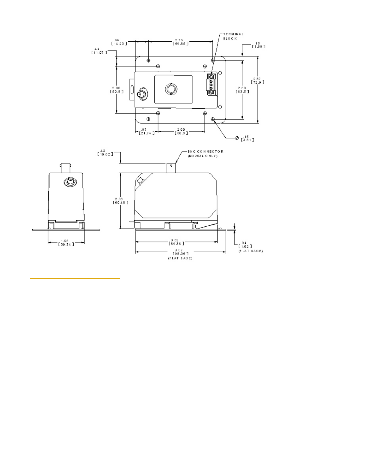
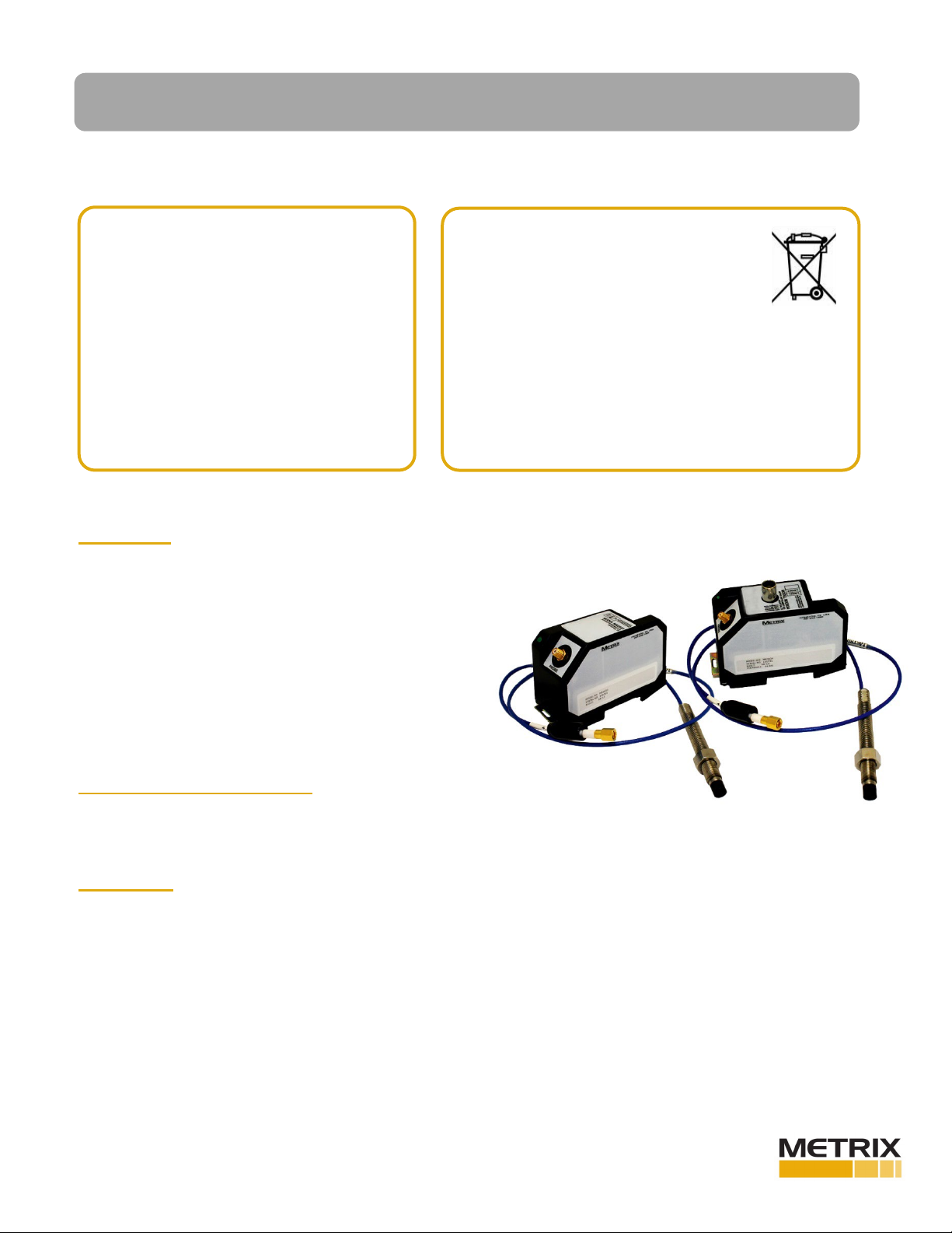
3. Mounting
Mount the DPS in a suitable enclosure in a location that is compatible with its environmental specifications (See Datasheet 10870151). The
driver or transmitter comes as a DIN rail mount. The below figure shows the unit with the optional flat base mounting plate, part number
9647. The 9647 mounting plate has two different hole patterns. One is for Metrix 5465/5488 transmitters and the other pattern is for Metrix
5533, MX3300 and most other manufacturers’ probe drivers.
Before proceeding to wire and install the Model
MX2033 or MX2034 Digital Proximity System (DPS),
read and thoroughly understand these instructions.
They are intended for experienced personnel who
require only basic installation guidance, and
assume that the DPS has already been selected and
applied properly for the machinery at hand. Please
contact Metrix or its local representative for
additional assistance. See also section 2 of this
manual for additional technical resources available
free-of-change on our website at
www.metrixvibration.com
This electronic equipment was manufactured
according to high quality standards to ensure safe
and reliable operation when used as intended.
Due to its nature, this equipment may contain small
quantities of substances known to be hazardous
to the environment or to human health if released into the
environment. For this reason, Waste Electrical and Electronic
Equipment (commonly known as WEEE) should never be
disposed of in the public waste stream. The “Crossed-Out Waste
Bin” label affixed to this product is a reminder to dispose of this
product in accordance with local WEEE regulations. If you have
questions about the disposal process, please contact Metrix.

Document 1232961 Hazardous Area Installation Manual – MX2033 and MX2034 Digital Proximity System Page 2 of 15
Rev. E (April 2022)
4. Extension Cable Installation
Route the extension cable using the following guidelines:
•Check that the Driver/Transmitter, extension cable, and probe belong to the same system (e.g. Metrix 10000 Series or 3300 series)
and that the total system length is correct (5m or 9m).
•Secure the extension cable to supporting surfaces or place in conduit. Make certain the cable is not kinked, scraped, nor bent
beyond the minimum recommended radius of 1”.
•Secure coaxial connectors between the extension cable and the proximity probe. Connection should be “finger tight”.
•Insulate the connection between the probe lead and the extension cable by wrapping the connector with Teflon tape and the Metrix
8973 connector insulator.

Document 1232961 Hazardous Area Installation Manual – MX2033 and MX2034 Digital Proximity System Page 3 of 15
Rev. E (April 2022)
5. MX2034 Intrinsically Safe 2 Wires, North America

Document 1232961 Hazardous Area Installation Manual – MX2033 and MX2034 Digital Proximity System Page 4 of 15
Rev. E (April 2022)
6. MX2034 Intrinsically Safe 4 Wires, North America
7. MX2033 Intrinsically Safe Wiring, North America
7. MX2033 Division 2 Wiring, North America

Document 1232961 Hazardous Area Installation Manual – MX2033 and MX2034 Digital Proximity System Page 5 of 15
Rev. E (April 2022)
7. MX2033 Intrinsically Safe, North America

Document 1232961 Hazardous Area Installation Manual – MX2033 and MX2034 Digital Proximity System Page 6 of 15
Rev. E (April 2022)
8. MX2034 Division 2 Wiring, North America

Document 1232961 Hazardous Area Installation Manual – MX2033 and MX2034 Digital Proximity System Page 7 of 15
Rev. E (April 2022)
9. MX2033 Division 2 Wiring, North America

Document 1232961 Hazardous Area Installation Manual – MX2033 and MX2034 Digital Proximity System Page 8 of 15
Rev. E (April 2022)
10. MX2034 Intrinsically Safe 2 Wires, Non-North America (EN/IEC Standards)

Document 1232961 Hazardous Area Installation Manual – MX2033 and MX2034 Digital Proximity System Page 9 of 15
Rev. E (April 2022)
11. MX2034 Intrinsically Safe 4 Wires, Non-North America (EN/IEC Standards)

Document 1232961 Hazardous Area Installation Manual – MX2033 and MX2034 Digital Proximity System Page 10 of 15
Rev. E (April 2022)
12. MX2033 Intrinsically Safe, Non-North America (EN/IEC Standards)

Document 1232961 Hazardous Area Installation Manual – MX2033 and MX2034 Digital Proximity System Page 11 of 15
Rev. E (April 2022)
13. MX2034 Division 2 Wiring, Non-North America (EN/IEC Standards)

Document 1232961 Hazardous Area Installation Manual – MX2033 and MX2034 Digital Proximity System Page 12 of 15
Rev. E (April 2022)
14. MX2033 Division 2 Wiring, Non-North America (EN/IEC Standards)

Document 1232961 Hazardous Area Installation Manual – MX2033 and MX2034 Digital Proximity System Page 13 of 15
Rev. E (April 2022)
DIV. 1 AND DIV. 2 AREA
WARNING - POTENTIAL ELECTROSTATIC CHARGING HAZARD - SEE INSTRUCTIONS
AVERTISSEMENT - RISQUE POTENTIEL DE RECHARGE ÉLECTROSTATIQUE - VOIR LES INSTRUCTIONS
FIELD WIRING TO TRANSMITTER MUST COMPLY WITH LOCAL CODE. TRANSMITTER PROVIDES
INCREASED SAFTEY CIRCUIT TO PROBE AND EXTENSION CABLE.
LE CÂBLAGE DE CHAMP À L’ÉMETTEUR DOIT RESPECTER LE CODE LOCAL. ÉMETTEUR FOURNIT UN
CIRCUIT INCREASED SAFTEY À SONDE ET CABLE D'EXTENSION.
DIV 2: THE PRODUCT IS REQUIRED TO BE POWERED THROUGH A CERTIFIED POWER SUPPLY.
15. Buffered Output Connections
There are connectors provided for access to the dynamic voltage output on the MX 2034 and the MX2032. On the MX2034 this is the BNC
connector. On the MX2032 this is the terminal pin labeled “TEST”. These connections are not approved for making temporary connections
in hazardous areas and both have the entity parameter Um=0.
16. Field Repair and Service
The DPS does not contain any user-serviceable parts and cannot be repaired in the field, except for a custom calibration that can be
completed using the DPS software. Replace a failed DPS with an equivalent unit.
17. Special conditions of safe use:
For Intrinsically Safe (Ex ia):
•
The protection concept used must be irrevocably marked on the label during installation
•
To reduce the risk of electrostatic ignition the equipment must be cleaned only with a damp cloth
For Increased Safety (Ex ec):
•
The protection concept used must be irrevocably marked on the label during installation
•
The equipment must be installed in a suitably certified enclosure such that it is afforded a degree of protection of at least
IP54 in accordance with EN 60529 and EN 60079-7 and is in an area of not more than pollution degree 2, as defined in
IEC/EN 60664-1
•
External transient supply limitation must be present that clamps at no more than 42V
When the apparatus is being used in accordance with the type of protection: Ex e IIC T4 (‐40°C ≤ Ta ≤ +85°C), the apparatus must be
mounted in an enclosure capable of withstanding a 7 Joule impact (at -40°C in non-metallic), provide a degree of ingress protection of at
least IP54, use in an area of no worse than pollution of degree 2, and voltage supply is externally clamped at no more than 42V (i.e. 140% of
30V). It is recommended to use “Ex e” or suitable “Ex n” enclosure because they meet IP54 after thermal endurance and 7 Joule impact
testing.
The apparatus is capable of withstanding the 600V insulation test required by clause 7.1 of EN 60079-07:2015.

Document 1232961 Hazardous Area Installation Manual – MX2033 and MX2034 Digital Proximity System Page 14 of 15
Rev. E (April 2022)
18. Hazardous Area Approvals
ETL Approval (North
America):
Intertek Markings:
Intrinsically Safe/Increased Safety
Class I, Div. 1 & 2, Groups A, B, C, D Temp Code
T4 (–40°C ≤ Ta ≤ +85°C)
UL/CSA Standards:
UL 60079-0:2019
UL 60079-7:2017
UL 60079-11:2013
CSA C22.2 60079-0:2015
CSA C22.2 60079-7:2016
CSA C22.2 60079-11:2014
Intrinsically safe: when
installed as per dwg 100506
Increased Safety: Field
wiring to transmitter must
comply with local code.
Refer to installation dwg
100512.
IECEx Approval
(World):
IEC Markings:
Ex ia IIC T4 Ga
Ta (–40°C ≤ Ta ≤ +85°C)
IECEx ETL 22.0014X
Ex e IIC T4 Gc
Ta (–40°C ≤ Ta ≤ +85°C)
IECEx ETL 22.0017X
IEC Standards:
IEC60079-0:2017
IEC60079-11:2011
IEC60079-7:2015
CAUTION:
Intrinsically safe: Only
resistively limited sources
are allowed. Electrostatic
hazard – clean only with
damp cloth.
CAUTION:
Increased Safety: Do not
seperate when energized.
ATEX/UKEX Approval
(Europe):
ATEX Markings:
II 1 G Ex ia IIC T4 Ga
Ta (–40°C ≤ Ta ≤ +85°C)
ETL 22ATEX0138X
ITS 22UKEX0528X
II 3 G Ex e IIC T4 Gc
Ta (–40°C ≤ Ta ≤ +85°C)
ETL 22ATEX0157X
ITS 22UKEX0533X
EN Standards:
EN60079-0:2018
EN60079-11:2012
EN60079-7:2015

Document 1232961 Hazardous Area Installation Manual – MX2033 and MX2034 Digital Proximity System Page 15 of 15
Rev. E (April 2022)
DPS
Metrix Instrument Company
8824 Fallbrook Drive
Houston, TX 77064 USA
(281) 940-1802
www.metrixvibration.com
info@metrixvibration.com
Trademarks used herein are the property of
their respective owners.
Data and specifications subject to change
without notice.
© 2013 Metrix Instrument Company, L.P.
PROBE/CABLE
Other manuals for MX2033
2
This manual suits for next models
1
Table of contents
Popular Industrial Electrical manuals by other brands

Murata
Murata GRT155R60J225KE01 Series Reference sheet

Murata
Murata GRM022R60J683ME15 Series Reference sheet

Murata
Murata GRM1885C1E821JA01 Series Reference sheet

Murata
Murata GJM0335C1H4R7BB01 Series Reference sheet

Softing
Softing FG-200 HSE/FF user manual

Siemens
Siemens 3VT9500-1U.00 operating instructions