Mex MPC-1054-FV User manual

MEX MPC-1054-FV
MPS-1054-FV
Water Purifier
MPC-1054-FV/MPS-1054-FV
Installation & Operation
Instruction Manual
User Installation and Instruction;
Model FV-10005 MANUAL FILTER
VALVE
THAI/ENG

2
PEN K INTER TRADIND CO., LTD.| TH
-
–
FV-10005 ………………………………………………………………………………………………………………………………………. –

TH| PEN K INTER TRADING CO.,LTD.
3
–
–
4.98–71.12psi (0.35 –5.0 )
%
PTFE)

4
PEN K INTER TRADIND CO., LTD.| TH
(
-
–
–
%

TH| PEN K INTER TRADING CO.,LTD.
5
Service@ 4.99 psi ……………………………………………………………………………………. 8.8
Backwash@ 4.99 psi ………………………………………………………………….…. 8.8
Fast Rinse@ 4.99 psi ……………………………………………………………………………. 8.8
1/2 –,
..... BSPF,
..... BSPF,
BSPF,
–……………………. 4.98-71.12 psi (0.35–5.0 )
……………………………...……………… - oF (- )
……………….…………………… - oF (- )
6
PEN K INTER TRADIND CO., LTD.| TH

TH| PEN K INTER TRADING CO.,LTD.
7
riser riser
bottom distributor)
2. riser
riser riser riser
Manual
Manual riser Manual
Service, Backwash Rinse
2.
MPC-1054-FV MPS-1054-FV
MPC-1054-FV MPS-1054-FV
Bypass valve

8
PEN K INTER TRADIND CO., LTD.| TH
adapter fitting)
½
1. Service
Backwash-
B’WASH Backwash
Backwash
Rinse
Service
TH| PEN K INTER TRADING CO.,LTD.
9

10
PEN K INTER TRADIND CO., LTD.| TH
Part No.
1
P1
2
P2
3
P3
4
P4
5
P5
6
P6
7
P7
8
P8
9
P9
10
P10
11
P11
12
M1
13
M2
14
M6x25
M3
15
M6
M4
16
R1
17
R2
18
R3
19
R4
20
R5
21
R6
22
R7

TH| PEN K INTER TRADING CO.,LTD.
11
1
, ,
*
--
Oxidation agent (, ,
12
PEN K INTER TRADIND CO., LTD.| TH
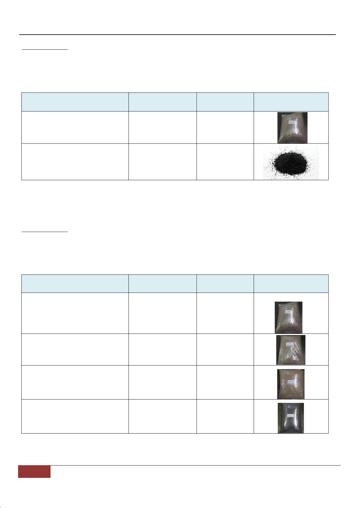
: MPC-1054-FV
(Media)
4 (Gravel 4 mm)
6.5
115.00
(Activated Carbon)*
20
,20
* MPC-1054-FV
: MPS-1054-FV
(Media)
4 (Gravel 4 mm)
6.5
115.00
2 (Gravel 2 mm)
10
(Sand No.0)
(Anthracite)
515.00

2
PEN K INTER TRADING CO.,LTD. |ENG
CONTENT
Safety Information ......................................................................................................................................................................................... 3 - 4
Typical Tools and Fittings Required ............................................................................................................................................................. 4
Specifications ..................................................................................................................................................................................................... 5
Valve Dimension and Valve Layout ............................................................................................................................................................. 6
Equipment Installation .................................................................................................................................................................................... 7
Operation of valve ........................................................................................................................................................................................... 7
Installation Procedure ……………………………………………………………….……………………………………………………………………….…………………….. 7 - 8
Operation ………………………………………………………………………………………………………………………………………………………………………………….… 8
Valve Assembly Model FV-10005 ………………………………………………………………………………………………………………………………..………. 9 –10
Warranty Terms and Conditions ………………………………………………………………………………………………………………………………………………... 11
Media …………………………………………………………………………………………………………………………………………………………………………………………… 12

PEN K INTER TRADING CO.,LTD. |ENG
3
Safety Information
General
Observe all warnings that appear in this manual.
This system is not intended to be used for treating water that is microbiologically unsafe or of unknown quality
without adequate disinfection before or after the system.
Keep the unit in the upright position. Do not turn on side, upside down, or drop. Turning the tank upside down
will cause media to enter the valve.
Operating ambient temperature is between 34°F (1°C) and 120°F (49°C).
Operating water temperature is between 34°F (1°C) and 100°F (38°C).
Working water pressure range is 4.98 to 71.12 psi (0.35 to 5.0 bar).
Follow state and local codes for water testing.
When filling media tank, do not open water valve completely. Fill tank slowly to prevent media from exiting the
tank.
Always make modifications to house plumbing first. Connect to valve last.
Mechanical
All plumbing must be completed according to local codes.
Observe local drain line requirements.
Do not use petroleum-based lubricants such as petroleum jelly, oils, or hydrocarbon-based lubricants. Use only
100% silicone lubricants.
All plastic connections should be hand tightened. Plumber tape should be used on connections that do not use
an O-ring seal. Do not use pliers or pipe wrenches.
Soldering of the plumbing should be done before connecting to the valve. Excessive heat will cause interior
damage to the valve.
Do not use lead-based solder for sweat solder connections.
Do not support the weight of the system on the control valve fittings, plumbing, or the bypass.
It is not recommended to use sealants on the threads. Use plumber tape (PTFE) on all threads.

4
PEN K INTER TRADING CO.,LTD. |ENG
Safety Information (Cont.)
Location Selection
Location of a water treatment system is important. The following conditions are required:
Level platform or floor.
Total minimum pipe run to water heater of ten feet (three meters) to prevent backup of hot water into system.
Local drain or tub for discharge as close as possible.
Water line connections with shutoff or bypass valves.
Room to access equipment for maintenance.
Outdoor Locations
It is recommended that the equipment be installed indoors. When the water conditioning system must be installed
outdoors, several items must be considered.
Direct Sunlight —The materials used will fade or discolor over time in direct sunlight. The integrity of the
materials will not degrade to cause system failures.
Temperature —Extreme hot or cold temperatures may cause damage to the valve or controller. Freezing
temperatures will freeze the water in the valve. This will cause physical damage to the internal parts as well as
the plumbing.
Typical Tools and Fittings Required
Pipe Cutter
Tubing Cutter
File
Pliers
Tape Measure
Soldering Tools
Lead Free Solder
Bucket
Towel
Plumber Tape
Adjustable Wrench
Tube 100% Silicone Grease

PEN K INTER TRADING CO.,LTD. |ENG
5
Specifications
Flow Rates (Valve Only)
Service @ 4.99 psi ……………………………………………………………………………………………………………………………………………. 8.8 gpm (33.33 lpm)
Backwash @ 4.99 psi ………………………………………………………………………………………………………………………….……………. 8.8 gpm (33.33 lpm)
Fast Rinse @ 4.99 psi ………………………………………………………………..……………………………………………………….……………. 8.8 gpm (33.33 lpm)
Valve Connections
Tank Thread .................................................................................................................................................. 2 1/2 inch (63.5 mm.) – 8, male
Inlet Thread ....................................................................................................................................................... 1 inch (22.5 mm.) BSPF, male
Outlet Thread ................................................................................................................................................... 1 inch (22.5 mm.) BSPF, male
Drain Line ........................................................................................................................................................... 1 inch (22.5 mm.) BSPF, male
Distributor Tube Diameter ........................................................................................................................................................ 1 inch (25 mm)
Design Specifications
Operating Pressure ............................................................................................................................................. 4.98-71.12 psi (0.35–5.0 bar)
Water Temperature ................................................................................................................................................................ 34-100°F (1-38°C)
Ambient Temperature*........................................................................................................................................................... 34-120°F (1-49°C)
* Recommended for indoor use only
6
PEN K INTER TRADING CO.,LTD. |ENG
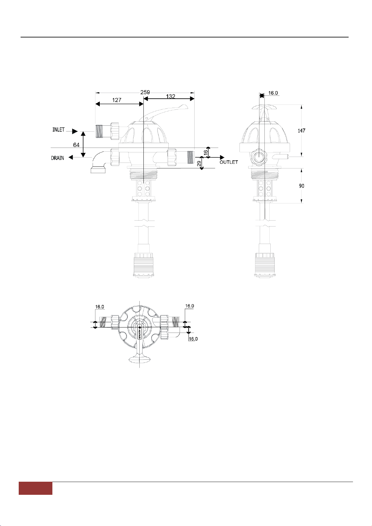
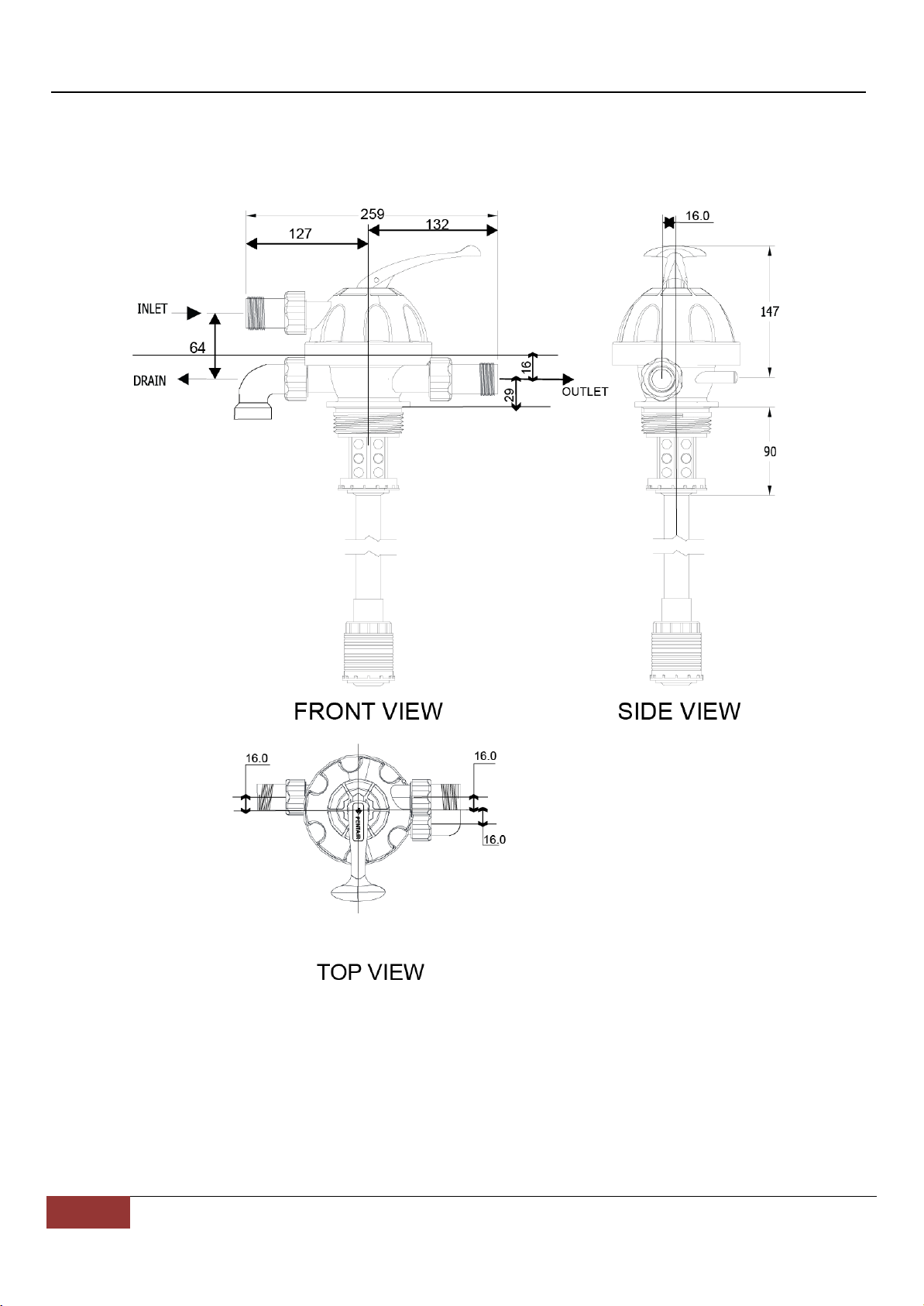
Valve Dimension and Valve Layout
Figure 1 Valve Dimension and Valve Layout

PEN K INTER TRADING CO.,LTD. |ENG
7
Equipment Installation
1. Take a 20NB Rigid PVC riser pipe, approximately the height of the vessel and solvent cement the bottom distributor to
one end of the pipe.
2. Insert this riser pipe into the vessel and cut the pipe from the top ensuring that the height of the pipe (with the
distributor touching the bottom) is the same as the top of the vessel.
3. Pour gravel and then filter media into the vessel. Cover the mouth of the riser pipe while doing this so that media
doesn't enter the pipe. Align the riser pipe so that it is in the Centre of the vessel opening.
4. Screw on the top distributor to the bottom of the MPV.
5. Screw on the MPV to the vessel ensuring that the riser pipe goes through the top distributor into the MPV.
6. Make the inlet, outlet and drain connection.
Operation of Manual valve
1. Always press the handle down before turning the handle to the desired position viz. Service, Backwash or Rinse.
2. If the line pressure is more, it is advisable to close the inlet valve before turning handle.
Installation Procedure
The following installation procedures shall be carried out by a qualified person. Read the installation and operation
manual carefully.
Installation
1. Place the MPC-1054-FV or MPS-1054-FV system where you want to install the unit.
2. Turn off the mains water supply.
3. Connect the inlet and outlet pipe of the system correctly using piping of the suitable diameter.
4. Cut a section of plastic hose of desired length. Connect it to the drain line of the system and fasten with hose hoop.
The other end of the hose runs to a drain and is secured in place.
5. Manual valve shall be installed at the inlet/outlet of the MPC-1054-FV or MPS-1054-FV system. A bypass valve is
recommended to be installed between the inlet and outlet of the system so that normal usage of water is not affected
during the maintenance of the system.
8
PEN K INTER TRADING CO.,LTD. |ENG
Drain line connection
Note: Standard commercial practices are expressed here. Local codes may require changes to the following suggestions.
Check with local authorities before installing a system.
1. The unit should be above and not more than 20 feet (6.1 m) from the drain. Use an appropriate adapter fitting to
connect 1-inch plastic tubing to the drain line connection of the control valve.
2. Where the drain line is elevated but empties into a drain below the level of the control valve, form a 7-inch (18 cm)
loop at the far end of the line so that the bottom of the loop is level with the drain line connection. This will provide an
adequate siphon trap. Tie or wire the hose in place at the drain point. Also provide an air gap of at least 1½ inch between
the end of the hose and the drain point.
3. Where the drain empties into an overhead sewer line, a sink-type trap must be used.
4. Secure the end of the drain line to prevent it from moving.
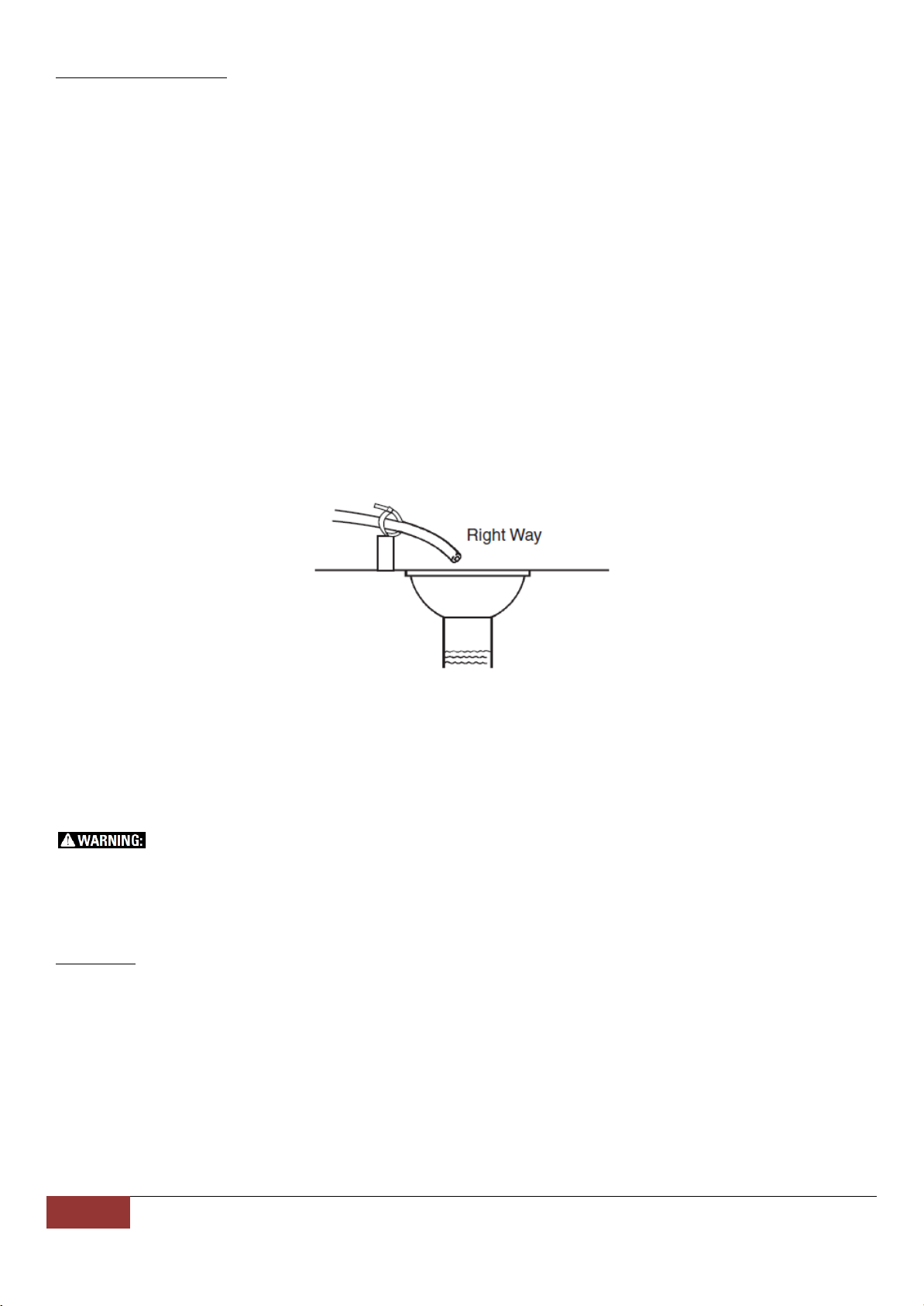
Figure 2 Drain Line Connection
NOTE: Waste connections or drain outlet shall be designed and constructed to provide for connection to the sanitary
waste system through an air gap of two pipe diameters or one inch (22 mm), whichever is larger.
WARNING: Never insert drain line directly into a drain, sewer line, or trap (Figure 2Drain Line Connection).
Always allow an air gap between the drain line and the wastewater to prevent the possibility of sewage being back-
siphoned into the filter.
Operation
1. Get started, Always press the handle down before turning the handle to the service position to filter the water.
2. You should be backwash after 1-3 days to clear the dirt from the filter. Always press the handle down before turning
the handle to the B'WASH position. Take 40 minutes to backwash.
3. After backwashing, wash for 20 minutes with the handle down before turning the handle to the Rinse position.
4. Then always press the handle down before turning the handle to the service position to filter the same.

PEN K INTER TRADING CO.,LTD. |ENG
9
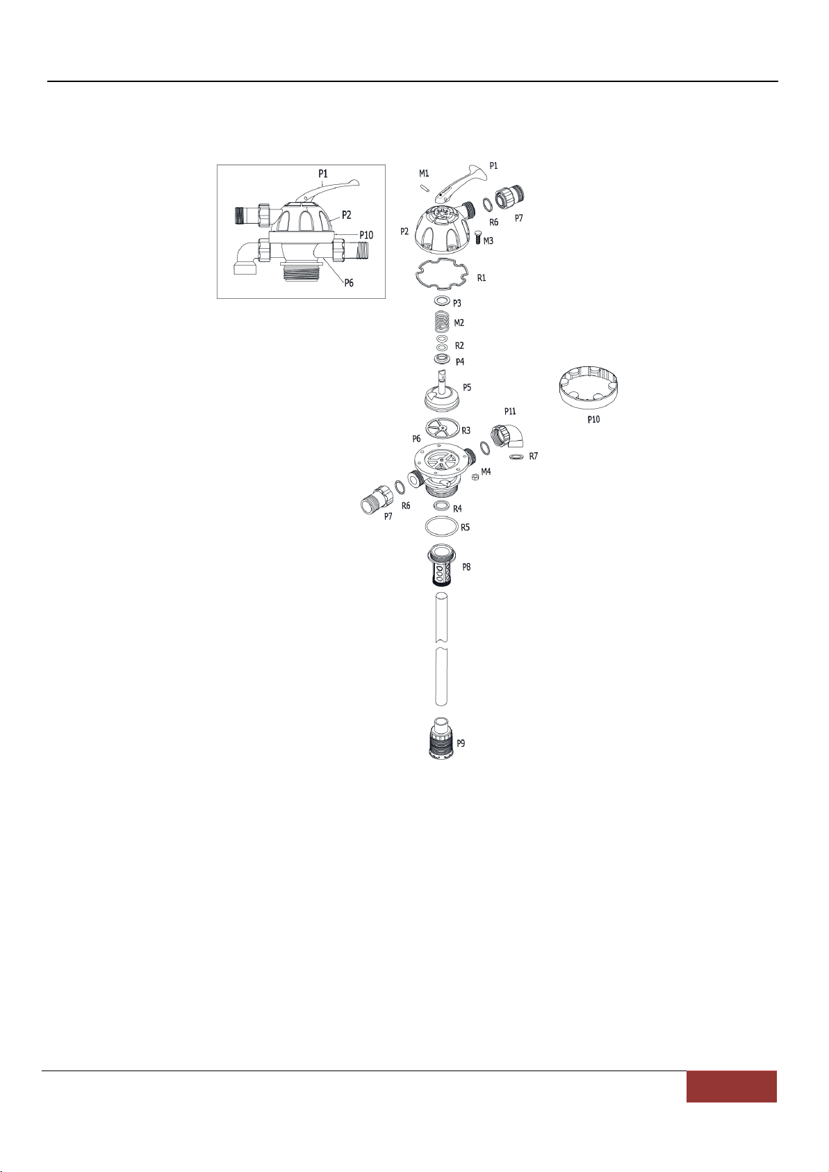
Valve Assembly Model FV-10005
Figure 3 Valve Assembly Model FV-10005
This manual suits for next models
1
Table of contents
Languages:
Popular Water Filtration System manuals by other brands


Emerson
Emerson A-W instruction sheet

Deltec
Deltec MCE 600 Operating instructions and spare parts list

First Choice
First Choice PRO CLEAN PCCF-075 owner's manual

KENT
KENT Grand+ Mineral RO Instruction handbook for installation, operation and maintenance

Pro Clear Aquatic Systems
Pro Clear Aquatic Systems REDFLEX REEF instructions

Fiberplex
Fiberplex Waveguide WGF-6 user manual