Meyer Sound LD-2 User manual

80Hz between the Mid-Bass
and Sub outputs. With the
switch out, a full range signal is
sent to both sections. Polarit
switches in both the Mid-Bass
and Sub sections allow quick
correction of an polarit
reversal or allignment
optimization problems. If onl
full range and subwoofers are
used in the main s stem, the
Mid-Bass/AUX section is
available for auxiliar s stems
such as front-fill, down-fill or
dela s.
A Master section includes a
gain control, a master Mute
switch with LED, and a signal
presence/clip LED. The
compact, single rack space
cabinet is made of 16-gauge
steel to provide magnetic
isolation from nearb devices,
EMI immunit and protection
from accidental impact damage.
AApppplliiccaattiioonnss
The LD-2 provides an
alternative to the larger LD-1A
line driver in applications where
coverage is supplied primaril
b the main Left and Right
s stems, with or without
subwoofers, and few (if an ) fill
or auxiliar subs stems are
used. T pical s stems using the
LD-2 could include concert halls
and performing arts centers,
nightclubs, houses of worship,
corporate presentations, and
touring s stems for small to
mid-sized venues.
The LD-2 is a compact, one
rack space device designed
specificall for integrating
different t pes of Me er Sound
self-powered loudspeakers into
an optimized full-range s stem.
As a line driver, the LD-2 can
connect to cable runs of up to
1000 feet without introducing
instabilit or distortion. In
addition, the LD-2 incorporates
a number of switching and filter
options to facilitate quick set-
up and accommodate a variet
of different s stem
configurations.
Each channel of the LD-2
includes three output/control
sections, designated Mid-Hi,
Mid-Bass/AUX and Sub. Each
section provides a gain control
(-12 to +6dB) and Mute switch
with LED. In addition, the Mid-
Hi section has an Arra EQ filter
to minimize the low-mid rise
caused b horizontal arra s of
three to five MSL-4 speakers;
and Low Cut filter which
performs a crossover function
b either sending a full range
signal to the Mid-Hi output or
rolling off at 160Hz
(12dB/octave). The Mid-
Bass/AUX section also includes
a low cut filter (160Hz,
12dB/octave). A separate Mid-
Bass and Sub Crossover switch
enables the LD-2 to
accommodate either Mid-Bass
or Subwoofers or both Mid-
Bass and Subs, in the same
s stem. With the switch
engaged, the signal divides at
AArrcchhiitteeccttss aanndd EEnnggiinneeeerrss
SSppeecciiffiiccaattiioonnss
The line driver shall be a
two channel device with one
input and three outputs for
each channel (Left and Right).
Each channel shall provide
dedicated control sections and
outputs for Mid-Hi powered
loudspeakers, Mid-Bass
powered loudspeakers or an
auxiliar s stem, and powered
Subwoofers. The Mid-Hi control
section shall provide gain
control over a -12 to +6dB
range, a Mute switch, a Low cut
filter (160Hz) and an Arra EQ
filter (-6dB at 220Hz, 0.6 octave
bandwidth). The Mid-Bass or
Aux section shall provide gain
control over a -12 to +6dB
range, a Mute switch, Low cut
filter (160Hz), and polarit
switch. The Subwoofer section
shall provide gain control over
a -12 to +6dB range, Mute
button, and polarit switch. A
Mid-Bass & Sub Crossover
Switch at 80Hz shall allow use
of either Mid-Bass or Sub for LF
reproduction, or both. Each
channe shall include a master
gain control over a -12 to +6dB
range, a signal presence/clip
LED indicator, master Mute
button, and an LED mute
indicator. All outputs shall be
on XLR-M connectors, and each
shall have an output
impedance of 10Ωand provide
a maximum output voltage of
±22.5Vpk. Inputs shall be
XLR-M connectors with a 10k
impedance. An internal power
suppl shall be switchable for
120V or 230V nominal
operation on 50 or 60Hz line
current. The line driver shall
be housed in a 16-gauge steel,
1U rack mount chassis.
The line driver shall be a Me er
Sound LD-2.
Superior
engineering
for the art
and science
of sound.
www.meyersound.com
FEATURES
PRELIMINARY
LD-2Line Driver
Integrates different
self-powered speakers
+
φ φ
Mid-Bass or AUX
0180
PUSH PUSH
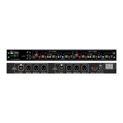
LD-2 Front Panel
LD-2 Rear Panel
Maintains signal integrity
over long cable paths
Separate Mid-Hi,
Mid-Bass/AU and
Subwoofer output controls
Optimized filters to
accommodate specific
array configurations

Master Left and Right Gain Controls
Mid-Hi, Mid-Bass/Aux, Sub Gain Controls
Low-cut Filter for Mid-High & Mid-Bass/Aux Output
Array EQ Filter for Mid-Hi Output
Mute
Polarity
Connector
Type
Impedance
Wiring
RF Filter
Common Mode Rejection Ratio
Signal Presence/clip LED
LED Threshold
LED Full Intensity
Type
Impedance
RF Filter
CCOONNNNEECCTTOORRSS
CONNECTORS Main
Wiring
DDRRIIVVEE CCAAPPAABBIILLIITTYY
DRIVE CAPABILITY Maximum Voltage
Maximum Current
Cables and Load
Connector
Operating Voltage
Maximum Power
Frequency Response
Bandwidth
Phase Response
Dynamic Range2
Noise Floor3
THD + N4
Gain Accuracy
Mute Attenuation
GGAAIINN RRAANNGGEE
GAIN RANGE Each Channel
Auxiliary Channels
Dimensions
Weight
Enclosure/Finish
Meyer Sound Laboratories, Inc.
2832 San Pablo Avenue
Berkele , CA 94702
tel: 510.486.1166
fax: 510.486.8356
e-mail: techsupport@me ersound.com
http: www.me ersound.com
© 2000 Me er Sound Laboratories, Inc.
All rights reserved
Meyer Sound reserves the
right to alter any specification
without notice.
Please visit our web site at
www.meyersound.com for
up-to-date information.
Meyer Sound Laboratories
has devoted itself to
designing, manufacturing,
and refining components
that deliver superb sonic
reproduction. Every part of
every component is
designed and built to
exacting specifications and
undergoes rigorous,
comprehensive testing
in the laboratories.
esearch remains an
integral, driving force
behind all production.
Meyer strives for sound
quality that is predictable
and neutral over an
extended lifetime and
across an extended range.
P ELIMINA Y
LD-2 SPECIFICATIONS
LD-2 – 04.088.004.01
Architecture
Audio Inputs
Audio utputs
AC Power
Audio
Performance
Physical
Notes
–12 to +6 dB
–12 to +6 dB
160 Hz high-pass, –12 dB/octave, Q = 0.8
6 dB cut at 220 Hz, 0.6 octave bandwidth
Mute switches for Master, Mid-Hi, Mid-Bass/Aux, and Sub outputs
Toggles for Sub and Mid-Bass/Aux outputs
1 female XLR per channel
Differential balanced input circuit
10 kΩ differential (between pins 2 and 3)
Pin 1: chassis/earth ground; Pin 2: signal; Pin 3: signal
Common Mode: 425 kHz low-pass; Differential Mode: 142 kHz low-pass
>80 dB (t picall 90 dB); measured in the range 50 Hz – 1 kHz
(Variable intensit ; monitored at the input for each channel)
–26 dBV (50 mVrms) pink noise or sinewave
–10 dBV (300 mVrms) pink noise or sinewave
Balanced, cross-coupled simulated transformer topolog
10Ω balanced (between pins 2 and 3)
Pins 2 and 3 shunted to chassis via 500 pF capacitance
1 female XLR/channel
Pin 1: chassis/earth ground; Pin 2: signal; Pin 3: signal
1600 Ω Load: ±22.5 Vpk (+24 dBV, +26.2 dBu sinewave)
No Load: ±25.0 Vpk (+25 dBV, +27.2 dBu sinewave)
±70 mApk (10 Vrms into 200 Ω)
Drives >100,000 pF (>1000 ft cable) without instabilit or distortion
IEC 320 (line, neutral/line, earth)
90 – 125 VAC / 180 – 250 VAC (selectable with rear panel switch);
50/60 Hz
25 Watts; Fuse: 5 x 20 mm, T 250 mA, 250 V, time-lag
<±0.2 dB 20 Hz – 20 kHz
DC to 60 kHz (–3dB)
<±3° from pure 3 µsec dela (DC – 20 kHz)
>120 dB
>–95 dBV A-weighted; >–90 dBV un-weighted
<0.005% (t picall 0.002%)
<±0.15 dB at +6 dB gain; < ±0.25 dB at 0 dB gain
>80 dB
–12 to +6 dB
Height: 1.75” (1 rack space); Width: 16.75”; Depth: 6.96”
13.5 lb (6.1 kg); shipping: 15 lb (6.8 kg)
Black 16-gauge steel chassis; 1/8” aluminum rack ears
1
1. 0 dBV = 1Vrms; 0 dBu =0.775 Vrms; 0dBm =1 mWrms
2. Ratio of maximum sinewave to A-weighted noise floor
3. Level set to unity gain (0 dB)
4. 0 dBV, 1 kHz sinewave input. Gain at +12 dB main channel
Other manuals for LD-2
1
Table of contents
Other Meyer Sound Music Equipment manuals
