Meyer Drive Pro User manual

Operation and Maintenance Manual
™

IMPORTANT NOTICE: In conjunction with FMVSS (Federal Motor Vehicle Safety Standards) and OEM (Original Equipment Manufacturer) guidelines,
Meyer Products LLC has designed this plow package with the following guidelines:
CAUTION: Installation of a snowplow may affect your new vehicle warranty. For more information consult your Vehicle Owner’s Manual / Vehicle Dealer.
WARNING: The vehicle must not be operated when overloaded. In all cases, the loaded vehicle weight, including the entire snowplow system, all aftermarket accessories,
driver, passenger, options, nominal fluid levels, and cargo must not exceed the front/rear Gross Axle Weight Rating (GAWR), and total Gross Vehicle Weight Rating (GVWR).
These weight ratings are specified on the safety compliance certification label on the driver’s side door opening. The use of rear ballast weight may be required to prevent
exceeding the front GAWR.
According to the NHTSA (National Highway Traffic Safety Administration) new and untitled vehicles need to be verified by the installer that snowplow and ballast (if needed) do
not exceed the front/rear GAWR and total GVWR.
manufacturer specifications for snow plow application.
WARNING: Deployment of an air bag while using a Meyer Snow
Plow will not be covered under Meyer Products’ warranty.
We also recommend that, for optimum performance, vehicles used for
snow plowing be equipped with:
• Four-Wheel Drive
• Minimum 60 Amp Alternator or larger
• Minimum 70 Amp Battery or larger (550 C.C.A.)
• Mud and Snow Tires
• Increased Radiator Cooling
• Automatic Transmission
• Power Brakes
• Power Steering
The Drive Pro™ Snow Plow system is designed for residential
plowing, to be used on 1/2 ton vehicles or lighter.
Under the continuing Meyer Product Improvement Plan, Meyer
Products LLC reserves the right to change design details and
construction without prior notice and without incurring any obligation.
Snow, despite the beauty it may impart to a bleak winter
landscape, poses the dual threat of inconvenience and danger. The
environmental conditions associated with snow, not to mention the
health hazards and economic loss it may impose, seriously endanger
thousands of lives annually. Business and industry suffer, and millions
of snowbelt residents may be affected by a single snowstorm.
Meyer Products LLC has published this manual to help you
get maximum performance from your Meyer Snow Plow and
familiarize you with the features designed for efficiency and
safety; be sure you recognize and understand them. Follow
recommended operation and maintenance instructions, so when
the storm hits, your Meyer Snow Plow will be ready and you will
know how to plow like a pro. DO NOT EQUIP ANY VEHICLE WITH
A SNOW PLOW WITHOUT CONSULTING MANUFACTURERS’
RECOMMENDATIONS.
Vehicles with Meyer Snow Plows installed may be so equipped as
to meet vehicle manufacturers’ specifications and recommended
options for snow plowing use. Most vehicle manufacturers insist
that vehicles which are to be used for snow plowing be equipped
with certain options and accessories, and it is so stated in vehicle
Introduction

SAFETY FIRST
Meyer Products LLC recommends that this manual be read
cover to cover so that you, the consumer, are completely
aware of all important safety recommendations.
Table of Contents Page
Get to Know Your Drive Pro™ Snow Plow 2-7
Snow Plow Operation, Maintenance & Adjustments 8-12
Hydraulic Power Unit Diagnosis Charts 13-15
Efficient Snow Clearance Starts with Planning 16
Plow with the Storm 17
Two Established Snow Clearance Plans 18
Snow Plowing Tips from the Pros 19-21
Minerals & Chemicals for Snow & Ice Control 22
Meyer Spreaders 23
Meyer Accessories 24-25
Genuine Meyer Parts 26-28
Meyer Warranty Back Cover
1
www.meyerproducts.com
e-mail [email protected]
SAFETY FIRST
Meyer Products recommends that this manual be read cover to cover so
that you are completely aware of all important safety recommendations.
Record your E-58H Serial Number and Moldboard Serial Number. These
serial numbers are printed on the E-58H unit decal and on the back of the
Moldboard on the part number decal
Be sure to REGISTER your Meyer Snow Plow
System online at www.meyerproducts.com to
ensure maximum warranty protection.
Hydraulic Lift Serial Number _________________
Moldboard Serial Number ___________________
THE INDUSTRY’S BEST
WARRANTY PROTECTION
2 YEARS STANDARD ON ALL COMPONENTS
3 YEARS ON ALL COMPONENTS*
5 YEARS ON ALL STRUCTURAL STEEL*
* Register at www.meyerproducts.com to activate years 3-5.

2
1. Moldboard
Steel sheet is bump and corrosion resistant. Built to last.
2. Cutting Edge
Replaceable high carbon steel provides extra long operating life;
should be 1/2” above ground in plowing position. (Can be higher
when used on gravel driveways.)
3. Runners
Adjustable and replaceable runners hold cutting edge at proper
height.
4. Trip Springs
Allow moldboard to trip forward and ride over obstructions, this
protects the snow plow, vehicle, and operator.
5. Pivot Bar
High quality steel - positions moldboard straight across, or angle
right or left.
6. Pivot Pin
Pin that attaches the pivot bar to the A-Frame.
7. A-Frame
Designed to attach the snow plow to the vehicle, to pivot moldboard
for angle plowing, and to hold plow at proper distance in front of
vehicle.
8. Power Angling Cylinders (1-1/2” x 10”)
Hydraulically positions the moldboard straight, or to right or left.
9. Clevis Frame
Allows snow plow assembly to be attached or detached from vehicle
in minutes.
10. Lift Frame
Allows for fast, complete removal of front end hardware, snow plow,
lights and hydraulic unit in one complete module.
11. Attaching Pins
Pull 1 handle to remove complete assembly.
12. Lift Arm
Chain locks in position to lift snow plow.
WARNING: LIFT ARM EXTENDS BEYOND BUMPER OF VEHICLE.
TO MINIMIZE DAMAGE FROM A FRONT END COLLISION, LIFT
ARM SHOULD BE REMOVED FROM VEHICLE WHEN SNOW
PLOW IS REMOVED.
13. Meyer Nite Saber® Snow Plow Lights
Complies with the Federal Motor Vehicle Safety Standards.
14. Electric Hydraulic Power Unit (E-58H)
Operates snow plow hydraulically- raises, lowers, angles, holds and
floats moldboard in plowing position.
15. Sno-Flo® Powder Coat
Baked on finish that looks like enamel, provides an extremely hard,
low friction surface that outlasts ordinary paint by a large margin.
Applied to all steel moldboards and mountings/frames.
16. Jackstand
Positions Moldboard and Lift Frame for easy attaching and
detaching.
™

3
E-58H (14)
™

DETACHING THE COMPLETE ASSEMBLY
Leave control switch in lower float position and push down on
the Lift Arm (4) approximately 1/4”. Disconnect the electrical
plug and slip on weather caps over the both ends. Remove
Safety Clip from jackstand. Push Jackstand Lever down,
until it is parallel with the cross bar of the Lift Frame, to lower
Jackstand to ground. At the same time push the top of the
Lift Frame up and towards the vehicle. Reinstall Safety Clip to
Jackstand below the lift frame. Pull, then rotate Handle so the
notch hooks onto the bracket on lift frame. The vehicle is now
free from mount and may safely back away.
ATTACHING THE COMPLETE ASSEMBLY
Check that the Handle Pin is disengaged. Drive the truck up
to the Drive ProTM assembly centering the hood of the truck
to the lift arm to assure proper alignment with lift frame guide
plates until contact is made. Once contact is made drive
forward, pushing the assembly a few inches. This insures
the A-Frame is square to the Clevis Frame for proper pin at-
tachment. The rear fixed Pins should now be aligned with the
rear notched hole on the clevis frame (1). Twist Handle Pin to
unlock so that the pins become spring loaded then push the
top of the Lift Frame towards the truck locking the front pins
to the clevis frame. Remove Safety Clip from jackstand. Push
Jackstand Lever down and raise Jackstand to storage posi-
tion. Reinstall Safety Clip to Jackstand above the lift frame.
Note: Wire Lynch Pin
(13) is used to Lock the
Jack Stand (3) in the
raised position once the
plow is attached to the
vehicle.
Caution: Crankstand
must be secured at all
times.
Reattach the one step
electrical connection.
4
™

5
Lower Plow to float position and manually
push lift arm down 1/4”. Disconnect the
electrical connection.
Remove Safety Clip from jackstand. Push
Jackstand Lever down to lower Jackstand
to ground. At the same time, push lift
frame up and toward the vehicle. Reinstall
Safety Clip to Jackstand below the lift
frame.
Pull, then rotate Handle so the notch
hooks onto the bracket on lift frame. The
vehicle is now free from mount and may
safely back away.
Removal
12 3
™

6
Drive into assembly until contact is made
and push assembly a few inches forward.
Rotate handle until engaged and push
top of lift frame towards truck until pins
click in place.
Remove Safety Clip from jackstand. Push
Jackstand Lever down and raise Jackstand
to storage position. Reinstall Safety Clip to
Jackstand above the lift frame.
Attachment
1 2 3
Always confirm pins are fully engaged before over the road or snow plow operation.
™

7
ADJUSTING CHAIN FOR PROPER SLACK WHEN
PLOWING SNOW
1. Be sure lift piston is fully retracted.
2. Hold chain taut and choose the third link above lift
arm, place that link in lift arm locking groove. This
procedure will provide the proper amount of slack
when snow plowing for the moldboard to follow
the contour of the ground. You may wish
to mark that link with paint or tape for easy
identification. Due to the differences in
vehicle ride heights, extra chain links may
vary in length. To prevent the extra chain
links from causing damage, remove or
secure the chain links together using an
electrical tie strap.
™

8
The snow plow should only be in operation when the vehicle ignition
switch and the Electro-Touch
®
control switch are in the “ON” position.
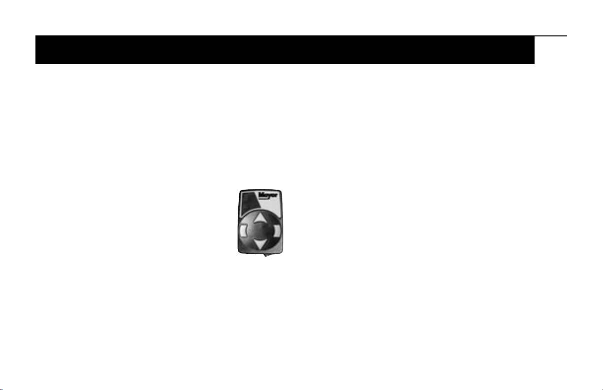
Care should be taken to insure that the Electro-Touch® control switch
is kept dry and free from moisture during normal operation.
When the Electro-Touch® control switch is turned “On,” yellow lights
illuminate the location of the individual touch pads for the functions of
the snow plow: (Up), (Angle Left), (Angle Right), and (Down).
Lowering of the snow plow an inch at a time is possible by tapping
the down arrow in short intervals. Holding down the
down arrow will activate a green light located in the
upper left corner of the Electro-Touch® switch. This
green light indicates the snow plow is now in the
Lower/Float position. In this position the snow plow
will be able to follow the contour of the road and the
snow plow can also be angled to the left or right.
Touching the up arrow automatically cancels the
Lower/Float position.
This switch is short circuit and temperature protected.
All wire connections must be securely plugged together. If any of
these conditions exist, the red overload LED will light. The overload
LED (red light) is located in the upper left corner below the float light
of the Electro-Touch® switch. Reset is accomplished by turning off
the ignition switch or by turning the power switch off momentarily
and then back on. If an overheating temperature condition exists,
it will be necessary to allow the unit to cool down for approximately
2 minutes. If the overload light is still illuminated after attempts to
reset the switch have failed, contact your nearest authorized Meyer
Distributor for repairs.
Electro-Touch Control
CAUTION: When the snow plow is not in operation, the Electro
Touch® Control Switch should be in the “OFF” position.
Over-the-Road Operation
WARNING
Based on the experience of our representatives and other background,
we advise a maximum transporting speed of 40 m.p.h. or locally
regulated speeds, whichever is less, dependent upon road conditions.
The operators should, of course, maintain a safe stopping distance and
adequate passing clearance at all times.
When transporting the snow plow to avoid engine overheating, angle
the moldboard completely, carrying it as low as permitted for safety by
road and surface conditions.
Pistol Grip Controller
The snow plow should only be in operation when the vehicle ignition
switch and the control switch are in the “ON” position. Care should be
taken to insure that the control switch is kept dry and free from moisture
during normal operation.
When the control switch is turned “On,” lights illuminate the location of
the individual touch pads for the functions of the snow plow: (Up), (Angle
Left), (Angle Right) and (Down). Also when the control switch is turned
“On” the snow plow lights are activated.
Lowering of the snow plow an inch at a time is possible by tapping the
down arrow in short intervals. Holding down the down arrow will activate
a float light located in the upper right corner of the control switch. This
Snow Plow Operation

9
light indicates the
snow plow is now in
the Lower/Float posi-
tion. In this position
the snow plow will
be able to follow the
contour of the road
and the snow plow
can also be angled
to the left or right.
Touching the up
arrow automatically
cancels the Lower/
Float position.
While angling left or
right or raising the
snow plow if the button is pressed for more than four seconds the
operation will be cancelled. This feature eliminates unnecessary amp
draw from the vehicle charging system.
This switch is self diagnosing. The monitor light is located in the upper
left corner next to the float light of the control switch. When the moni-
tor light turns on and begins to flash the control switch is sensing a
problem with a specific coil/connection on the hydraulic unit. The label
below is on the back side of your control switch.
Reset is accomplished by turning off the ignition switch or by turning
the power switch off momentarily and then back on. If the monitor
light is still illuminated after attempts to reset the switch have failed,
contact your nearest authorized Meyer Distributor for repairs.
22690
Pistol Grip Controller

10
Meyer Products recommends this maintenance information for regular
service. Sustained heavy operation may call for more frequent
service. Snow plowing subjects a vehicle to exceptionally rugged
use. As a result, it is important to inspect and bring the snow plow
and vehicle up to maximum operating conditions. Inspection should
be made of both the vehicle and snow plow prior to the plowing
season and after each use.
IMPORTANT: Maintenance and repairs should be performed with
the moldboard on the ground.
Pre-Season Maintenance
Scheduled vehicle maintenance should be performed as recommended
by the manufacturer.
Don’t forget that in addition to keeping equipment in order:
1. Keep windshield wipers, heaters and lights working.
2. Use emergency flasher lights for increased visibility and safety.
Meyer offers as standard equipment quartz halogen snow plow lights
for even brighter illumination.
3. Equip vehicles with chains where necessary.
4. Provide operators with protective clothing and with rubber gloves for
handling snow melting chemicals.
VEHICLE ELECTRICAL SYSTEM — For maximum efficiency, the
vehicle supporting the snow plow must be properly serviced. The
system should consist of at least a 70 amp/hr. battery and a 60 amp
alternator. Be sure to check regularly:
1. Battery terminals to assure they’re clean and free of corrosion.
2. Electrical connections, to assure they’re tight and corrosion-free.
Taping may be called for. All wires must be held clear of moving or
hot engine parts or sharp sheet metal.
3. Battery must be in top operating condition.
4. Alternator and regulator, to assure maximum electrical output.
SNOW PLOW
NOTE: Always lower moldboard to ground when vehicle is not
in use. Check the Electro-Touch® Diagnosis Chart, page 13-
15 , and Post Season Maintenance, page 11-12, for advice on
maintaining the unit.
General Maintenance

11
1. Check and maintain hydraulic fluid reservoir level to 1” - 1-1/2” from
top cap. Oil level should be checked with lift ram in the down position.
2. Check entire hydraulic system for leaks. A significant drop in
hydraulic fluid level is evidence of a leak which must be corrected
to prevent serious damage. See page 13.
3. Before and after each season, grease pivot tubes. Lubricate all
pivot points with chassis lube.
4. ADJUSTING TRIP SPRING TENSION - Tighten top
locknut 4 turns beyond the point when spring coils
begin to separate. Tighten bottom locknut to hold
eye bolt in position as shown.
5. RUNNERS
A. Inspect moldboard runners for wear and height
adjustment.
B. Always replace runners as soon as they start to
wear through.
C. Adjust the runners to maintain cutting edge height
of 1/2” above ground in snow plowing position. (Can
be set higher when used on gravel driveways).
6. CUTTING EDGE
Replace the cutting edge as soon as it appears worn approximately
4” on either corner. This will prevent permanent damage to the
moldboard.
7. MOUNTING BOLTS
Retighten all mounting bolts after first snow plowing session and at
regular intervals through the season.
8. SNO-FLO® POWDER COATING, both black and yellow, should be
checked at the beginning and end of each season for any signs of
rust. If any exists, use Meyer special Sno-Flo® powder coat
touch-up available in spray cans.
NOTE: PROTECTION AGAINST RUST AND CORROSION
When the power unit is not used for extended periods, protect the
chromed lift piston by fully extending and coating it with chassis
lubricant. On power angling models, coat the exposed portions
of the power angling cylinder rods with chassis lubricant to protect
against corrosion.
Post Season Summer Maintenance
1. Draining & Replacing Meyer M-1 Hydraulic Fluid
Drain fluid through drain hole in base, shown in Figure 0-3, by
completely retracting cylinder lift position and unbolting unit to pour
fluid out, or use a suction pump. On models without drain plug,
fluid must be drained by removing filler plug and turning unit upside
down. Follow same procedure of retracting cylinder lift piston. On
Power Angling models, disconnect the fittings at the Power Angling
cylinders, completely retract the cylinder rods and purge cylinders
and hoses of all hydraulic fluid. The complete hydraulic system
should then be flushed out with Meyer Hydra-Flush before adding
new Meyer Hydraulic Fluid.
2. Screen-Type Filters - Clean the filters (all models) with mineral
spirits or equivalent and blow out with compressed air. See Figure
0-3.

12
3. Meyer Hydraulic Fluid M-1 is specially formulated with an anti-ice
additive for almost constant viscosity in subzero temperatures.
Because it is free-flowing in extreme cold, the unit’s performance
and efficiency are not affected by winter weather. It is effective
for a maximum of one year. Always carry an extra quart of Meyer
Hydraulic Fluid M-1 or equal fluids. Use of any inferior fluids will
void the Meyer warranty.
4. Refill power unit with Meyer Hydraulic Fluid M-1 by fully retracting
lift piston and filling reservoir to 1-1/2” below the filler hole. On
Power Angling models, fill and bleed hoses and Power Angling
cylinders by loosening hydraulic fittings at cylinders until they leak.
Power angle the plow repeatedly from one side to the other unit
fluid flows steadily from the fittings while maintaining a constant
check on the reservoir fluid level. The filling end of the cylinder
should be higher than the piston end to facilitate removal of air.
Raise and lower the plow several times. With lift rod fully retracted
check fluid level and replace filter plug.
SNOW PLOW STORAGE
1. When snow plow is disconnected, extend lift cylinder to end
of stroke and coat chrome rod with light grease. This fills the
cylinder with hydraulic fluid and protects the interior and exterior
from rust and corrosion.
2. Whenever Moldboard is disconnected, coat the exposed portions of
the power angling cylinder chrome rods with light grease to protect
them from corrosion.
3. Be sure to reconnect optional quick couplers at the P.A. Rams to
keep them clean and prevent contamination of the system.
4. Coat all pivot pins and other wear points with chassis lubricant.
5. Unplug all electical connections at power unit. Coat all connections
with a dielectric compound to prevent corrosion and plug into
their corresponding weather plugs. Unplug the snow plow lights,
tape or use a dielectric compound at light connections to prevent
corrosion.
6. WARNING: LIFT ARM EXTENDS BEYOND BUMPER OF
VEHICLE. TO MINIMIZE DAMAGE FROM A FRONT-END
COLLISION, LIFT ARM SHOULD BE REMOVED FROM VEHICLE
WHEN SNOW PLOW IS REMOVED.
Fig 0-3
E-58H
Filler Hole and Relief Valve Lift Rod
Drain Plug
Filter Port
“B” Solenoid (Red)
“C” Solenoid (Green)
“A” Solenoid (Black)
Non Adjustable
Crossover Relief Valve
Lower Adjustment Screw
Filter Port
(under block)
“B” Check Valve
Left Angle
Cylinder Connection
Right Angle
Cylinder Connection

13
TESTING TIPS
Many tests do not require removing the Power Unit from the vehicle. However,
more thorough testing can be done by using the Meyer Test Stand which allows
direct pressure and Amperage readings.
1. Use a screwdriver or other small tool to check for magnetism of solenoid coils
“A”, “B” & “C”. Place the tool on the side of the coil and have an assistant
operate the switch. You should feel strong magnetic attraction.
2. Use a test light or volt meter to determine whether there is power at harness or
switches. (The wire must be probed)
3. When determining Ampere draw of motor, always obtain the highest value
possible, i.e., at maximum raise or angle with motor running.
4. Proper rotation for motor is indicated by an arrow on the top of the E-58H pump.
5. The pump shaft (all models) of a good pump can be turned smoothly using two
fingers. If it can’t be turned easily, the pump is too tight and must be replaced.
6. Pump pressure can be measured at an angle hose (note pressure at full angle) or
in the pressure filter port (an adapter is necessary for the filter port). (See Figure
0-3.)
7. If hydraulic system is contaminated it is recommended that the hydraulic unit,
power angling rams and hoses be drained and flushed clean. The system
should then be refilled with Meyer M-I oil. See pages 19-20.
GENERAL INFORMATION
Before any troubleshooting is started, make certain the
following conditions are met.
1. The moldboard is pointing straight ahead. This can often
be done by connecting the hose from the left cylinder into
the right cylinder and pushing the snow plow by hand.
2. The power angling cylinders must be installed correctly.
Reverse them if installed on wrong side. (See Figure 0-3)
3. The solenoid coils must be on their proper valve: the
“C”- coil (green and white wire), the “B”-coil (red and
white wire) and the “A” coil (black and white wire).
4. The electrical installation must have been made according
to instructions supplied by Meyer Products.
These charts are intended to be used as an aid in diagnosing problems on Meyer Hydraulic Power Units. They are not a substitute for factory train-
ing and experience. Be certain to read the General Information and Testing Tips sections before attempting any troubleshooting. Additional detailed
information as well as all electrical schematics may be found in Service Manuals 1-822.
DIAGNOSTIC FLOW CHART FOR
ELECTRIC HYDRAULIC POWER UNITS

14
Electric Hydraulic Power Unit Diagnosis
Chart
MODEL CONDITION POSSIBLE CAUSE CORRECTION
All Plow does not lift or lifts 1. Low hydraulic fluid level. 1. Add fluid to proper level
Power slowly - motor operates. 2. Discharged battery. 2. Recharge battery.
Angling 3. Leaking or open “A” cartridge. 3. Clean or replace “A” cartridge.
Models 4. No current to “B” coil. (red and white wire) 4. Locate malfunction and repair.
5. Inoperative “B” coil. (red and white wire) 5. Replace “B” coil. (red and white wire)
6. Malfunctioning motor. 6. Repair or replace motor.
7. Malfunctioning pump. 7. Replace pump.
All Plow does not angle right - 1. Improper coupler arrangement. 1. Engage coupler properly.
Power motor operates. 2. Mechanical bind or interference. 2. Eliminate mechanical bind or interference.
Angling 3. Malfunctioning coupler. (if equipped) 3. Repair or replace coupler.
Models 4. No current to “C” coil. (green and white wire) 4. Locate malfunction and repair.
5. Inoperative “C” coil. (green and white wire) 5. Replace “C” coil. (green and white wire)
6. Inoperative “C” cartridge. 6. Clean or replace “C” cartridge.
7. Leaking or open crossover relief valve. 7. Clean or replace crossover relief valve.
All Plow does not angle left - 1. Improper coupler engagement. 1. Engage coupler properly.
Power motor operates. 2. Mechanical bind or interference. 2. Eliminate mechanical bind or interference.
Angling 3. Malfunctioning coupler. (if equipped) 3. Repair or replace coupler.
Models 4. Leaking or open crossover relief valve. 4. Clean or replace crossover relief valve.
All Plow will not angle - 1. Improper coupler engagement. 1. Engage coupler properly.
Power motor operates. 2. Mechanical bind or interference. 2. Eliminate mechanical bind or interference.
Angling 3. Leaking or open crossover relief valve. 3. Clean or replace crossover relief valve.
Models
All Plow will not hold in 1. Air in cylinders and hoses. 1. Bleed cylinders and hoses. Tighten P.A.
Power angled position. 2. Leaking or open dual pilot check valve. cylinder gland nut.
Angling 3. Leaking crossover relief valve. 2. Clean or replace pilot check valve.
Models 4. Crossover relief valve opening at 3. Clean or replace crossover relief valve.
too low a pressure. 4. Replace crossover relief valve.

15
Electric Hydraulic Power Unit Diagnosis
Chart
MODEL CONDITION POSSIBLE CAUSE CORRECTION
All Motor does not operate. 1. Discharged or defective battery. 1. Recharge or replace battery.
Power 2. Loose or corroded electrical connections. 2. Clean and tighten electrical connections.
Angling 3. Inoperative starter solenoid. 3. Replace starter solenoid.
Models 4. Malfunctioning control switch. 4. Replace control switch.
5. Malfunctioning motor. 5. Repair or replace motor.
All Plow does not lower. 1. No current to “A” coil. (black and white wire) 1. Locate malfunction and repair.
Power 2. “A” cartridge jammed in closed position. 2. Clean or replace “A” cartridge.
Angling 3. Inoperative “A” coil. (black and white wire) 3. Replace “A” coil. (black and white wire)
Models 4. Lower Adj. screw 4. Adj lower Adj. screw
All Plow creeps down. 1. Leaking “A” cartridge. 1. Clean or replace “A” cartridge.
Power 2. Leaking “A” cartridge O-ring. 2. Replace O-ring.
Angling 3. Leaking “B” check valve. 3. Clean or replace “B” check valve.
Models 4. Leaking Ram Packing Cup. 4. Replace Ram Packing Cup.
5. Leaking O-ring at bottom of lift cylinder. 5. Replace O-ring.

16
PREPARING AREAS, USE OF GUIDE MARKERS
Every area to be plowed should be inspected before
snowfall for potential hazards. Holes should be repaired,
raised manhole covers leveled or noted and obstructions
noted to prevent damage to the plow mounting or vehicle
undercarriage.
Markers or stakes with reflectors should be in position to
indicate boundaries of areas to be plowed, location of
shut-off valves, catch basins and other hazards. Markers
should be at least three feet above the ground; higher in
areas of deeper snowfall.
The first step in organizing an efficient plan is to prepare a
map or procure a blueprint of the area. Locate and mark
all utilities, outlets, shutoffs, catch basins and possible
emergency equipment that must be reached from outside.
Figure the square footage of each area and the total area.
Especially note areas from which snow will have to be carried,
call “trapped” areas. Although hauling is expensive, it is
necessary where piled snow would limit access. Indicate
clearing priorities on your map.
This may aid you in preparing a priority plan for your
clearance operation.
KEEP SNOW UNDER CONTROL
Deep or heavy, wet snow, because of its increased weight, calls
for more skillful and powerful plowing than light powder snow.
Always plow in low gear and keep plowing. Heavy snow may
also require clearing a path or area for working room to move
snow to another area. Remember that wet snow weighs about
12 pounds per cubic foot. As it piles up in front of a snow plow
blade, the weight can quickly increase to several tons.
Where packed snow or ice must be plowed, it is sometimes
necessary to lower the cutting blade to rest directly on the
surface. In that situation, plow in lowest gear for greatest power
to the cutting edge. This method also prevents the plow from
“climbing over” the icy surface.
If plowing very deep snow, 12 inches or more, you may have to
plow with the blade partially raised to shear off successive layers
of snow until a working area is clear. Then work small “bites” into
the edge. The “bite” depth should be inversely proportional to
the snow depth. A rule of thumb: 6-inch snow may be plowed
with the entire blade width; 9-inch snow with 3/4 of the blade
width; and 12-inch snow with only 1/2 of the width. Experience
will show what work can be done without stalling or getting
stuck.
Efficient Snow Clearance Starts with Planning

17
It is of utmost importance to remember one basic rule --
Always plow with the storm. Start plowing when snow is 1
to 4 inches deep, depending upon traffic or other limitations.
Heavy wet snow can be very hazardous when just 1 inch is on
the ground. Accumulations of more than 4 inches can be very
difficult to clear.
Angle Moldboard for Optimum Results. You will not be able
to plow snow of any significant depth straight ahead for more
than a short distance. Set the moldboard at the best angle
for rolling snow sideways in the desired direction. The snow
plow path, in the angled position, should exceed the tire track
by at least two inches on either side. Be sure to have enough
slack in the lift chain while plowing so the cutting edge of the
moldboard can follow the ground contour. Use the adjustable
runner shoes to set the bottom edge of the plow just above
the ground for best operation.
It’s important to recognize the significance of even a
few inches of snow. Besides being slippery, especially
when wet, snow can be extraordinarily heavy, and make
auto travel impossible. Snowfall of just 1 to 3 inches will
produce hazardous traffic and roadway conditions even for
experienced drivers.
Snow is heaviest when wet, and most difficult to handle. The
National Weather Service reports that a 6-inch, average weight
snowfall on a 200 x 200 foot parking lot weighs 62 tons.
Heavy, wet snow for the same area might weigh as much as
248 tons. If the heavy snow had to be hauled away, you’d
need 74 full loads on a l0-yard truck.
Obviously, the only way to assure clear traffic areas is to be
prepared with the proper equipment. Remember to keep
current with accurate snowfall information from local weather
bureaus via radio and television.
Plow with the Storm

18
Recommended equipment: A four wheel drive vehicle; a Drive
Pro™ 6’-8” snow plow; snow shovels; and ice control equipment.
Recommended procedure: PLOW WITH THE STORM.
Begin plowing at the suggested accumulation for your type of
establishment. Continue until snow has been cleared. Don’t
forget - snowfall often surpasses weather forecasts. A well
planned clearing schedule will help prevent the necessity for
expensive emergency action.
A typical small-area strategy:
1. Keep in touch with local weather forecasts for preparatory
measures.
2. Notify scheduled personnel.
3. Have vehicles and equipment inspected, fueled and ready.
4. Clear area by pushing snow first to sides of drives. It is
often true that the smaller the establishment, the greater the
proportion of “trapped” areas which will require snow to be
hauled away. Always deposit snow as far back as possible
for greatest use of dumping areas.
5. Use snow shovels to clear walks, gates and doorways.
6. Treat with snow-melting materials as needed.
Established Snow Clearance Plan
Other manuals for Drive Pro
1
Table of contents
Popular Dj Equipment manuals by other brands

ETC
ETC Prodigy FlyPipe Studio installation guide

Chauvet DJ
Chauvet DJ Geyser P6 user manual

thomann
thomann Stairville CLB5 6P RGB WW Compact LED Bar user manual

PR Lighting
PR Lighting PR-8102 product manual

Chauvet
Chauvet Maverick MK2 Wash Quick reference guide

PR Lighting
PR Lighting XR440 BEAM user manual

Triton Blue
Triton Blue MF-7 user manual

Studio Technologies
Studio Technologies 236 user guide

Cobra Lighting
Cobra Lighting P64-180 user manual

Event Lighting
Event Lighting LM60S user manual

VanGaa Lighting
VanGaa Lighting VG-4HS432D user manual

ADB Stagelight
ADB Stagelight EURODIM Twin Tech installation manual