MFB SYNTH Pro User manual

SYNTH PRO
Operating Manual
1

IMPRINT
MFB – Ingenieurbüro Manfred Fricke
Neue Straße 13
14163 Berlin
Germany
www.mfberlin.de
2

Disclaimer
MFB does not assume any liability for completeness or accuracy for
any of the pages in this manual. We reserve the right to change any
of the terms and contents at any time without advance notice. The
content of this manual has been compiled with meticulous care and
to our best knowledge. MFB does not take responsibility for any
warranties for this manual beside the ones being defined by the
corresponding commercial laws.
Any duplication, processing or form of distribution of this manual or
parts of it requires permission of the manufacturer.
Safety Instructions
Please carefully read the following safety instructions! These include
general rules of handling electric products. Carefully read all notes
before operating the unit.
Suitable place of installation
Only use this device in confined spaces, avoid humidity and dust.
Ensure unhindered airflow to all sides of the device. Do not place
the device in direct proximity to heat sources.
Do not expose the device to direct sunlight or strong vibrations.
Electrical connection
Please only use the power supply that comes with the device. It
can be used with a supply voltage of 110 to 240 volts (mains).
If the provided power supply does not suit your power socket,
please consult a qualified electrician.
Unplug the power supply if you are not going to use the device
for a longer period.
Never touch the power supply with wet hands.
While unplugging, always pull the plug not the cable!
3

Operation
Never place containers of liquid on the device.
Ensure a safe and firm stand when in use.
Make sure no objects get inside the device. Should this happen,
switch off the device and remove it from the receptacle. Consult
a qualified dealer.
Maintenance
Do not open the device. Repairing and servicing must only be
carried out by qualified personnel. There are no user serviceable
parts inside the device. In addition, unauthorized opening of the
device renders the warranty void.
Only use dry and soft cloth or a brush for cleaning. Alcohol,
solvents or comparable chemicals will damage the device's
surface.
Intended use
This device has exclusively been designed to generate and process
audio signals as well as control signals corresponding to MIDI-, M-Bus-
and USB-specifications. Any further use is not allowed and will
preclude any warranty claims against MFB.
Disposal
This unit has been manufactured RoHS-conforming in compliance
with the requirements of the European parliament and council and
thus is free from lead, mercury, cadmium and hexavalent chromium.
Nevertheless, disposal of this product is classified as special waste
which must not be disposed with general household waste!
For proper disposal please refer to your dealer or to:
MFB - Neue Straße 13 - 14163 Berlin - Germany
4

Table of Contents
General …................................................................................................6
Starting up …........................................................................................... 6
Operation …............................................................................................ 7
Oscilloscope ........................................................................................... 7
Voice Display ..........................................................................................8
PRESETS – Selection and Storing …........................................................8
MENU Voice Mode ….............................................................................8
OSCILLATORS ….......................................................................................9
•Pitch …........................................................................................ 9
•DCO-mode and Auto Tuning …...............................................10
•Waveforms …............................................................................. 11
•Modulation ….............................................................................11
•Glide …........................................................................................11
•Synchronization …...................................................................... 12
•Frequency Modulation (FM) ….................................................12
•Oscillator Mix ….......................................................................... 12
FILTER ….................................................................................................... 13
•Modulation ….............................................................................14
•Filter Output …............................................................................14
ENVELOPES ….......................................................................................... 15
LFOs …...................................................................................................... 15
VCA …......................................................................................................16
EFFECTS …................................................................................................ 17
MASTER ….................................................................................................17
SEQUENCER …......................................................................................... 18
•Sequence – Selection and Storing …...................................... 18
•Sequence – Input and Playback ….........................................18
ARPEGGIATOR ….................................................................................... 19
•Shuffle and Tempo …................................................................ 19
•Transpose …................................................................................20
MIDI-SETTINGS …......................................................................................20
DATA-TRANSFER ….................................................................................. 20
REAR PANEL – CONNECTIONS .............................................................. 21
MIDI-IMPLEMENTATION …....................................................................... 22
Hint: To provide a better overview, we have added a schematic of
the described section in each chapter. All labelings of the controls,
buttons and jacks are being printed bold in this manual and written
as labeled on the device itself.
5

General
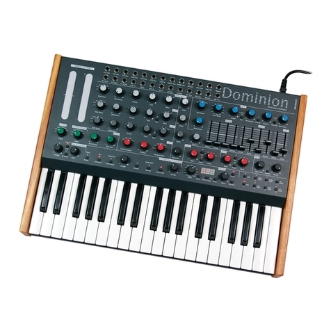
MFB SYNTH PRO is a synthesizer with eight voice polyphony. Its
analog sound engine is based on circuits and techniques which
have been used in synthesizers of the 70s and 80s and have been
updated and expanded by useful functions. Among the special
features of SYNTH PRO are the oscillators which can seamlessly blend
between waveforms. The VCOs can alternatively being used in a
DCO-mode. The filter section offers two separate VCFs (per voice)
with different characteristics which can be coupled to be controlled
simultaneously. In addition, SYNTH PRO offers 240 storage locations, a
polyphonic sequencer, an arpeggiator, extensive controllability via
MIDI-controllers and a digital effects processor.
Starting up
SYNTH PRO is powered by an external power supply which is
connected to the 6V/1,5A jack on the unit’s rear panel. Find the
POWER ON/OFF located alongside. Prior to switching on the device,
connect the AUDIO OUT jack to a mixing console, an audio-
interface or an amplifier. Switch SYNTH PRO on or off using the
corresponding switch.
SYNTH PRO can be played by a keyboard or an external sequencer
using the MIDI protocol. To do so, connect the MIDI IN input or USB
KEYS to the MIDI-output of a keyboard or to a MIDI-interface of a
computer running a DAW.
Hint: Since SYNTH PRO is an analog synthesizer, you should always
allow a warm-up-period of approx. five to ten minutes to achieve
tuning stability.
Presets that have been programmed using the VCO-mode may
sound detuned or “strange” compared to the stored version during
this period. For this period, but not only for that, SYNTH PRO offers the
option to switch to DCO-mode which is always stable in tune.
In case, FM has been used in a preset, make sure the operating
temperature for the circuit has been reached since FM is not
available in DCO-mode.
6

Operation
All sound shaping functions of SYNTH PRO can be adjusted using
dedicated control elements. Parameters and values currently being
changed will be displayed in the topmost display-row.
Additional functions for each section, such as modulation routings,
are available via menus which are selected using the display and
the MENU encoder. Each menu offers (up to) three sub-entries,
which are selected by pressing the VALUE encoder consecutively.
The selected parameter changes in color from red to green and
can be adjusted using the VALUE encoder.
The display shows parameters in six rows.
1 – the function last used: value
2 – selected menu
3 – menu-parameter 1: value
4 – menu-parameter 2: value
5 – menu-parameter 3: value
6 – varying notifications – preset, bank, FM select, MISC-functions
Oscilloscope
By pressing the MENU encoder, the display changes to a real-time
waveform-display.
Below the waveform, trigger and timing-values can be adjusted.
Return to the regular display-menu by pressing the encoder again.
7

Voice Display
Four LEDs below the VALUE encoder display the currently active
voices. Voices 1 to 4 are visualized red, voices 5 to 8 in green.
PRESETS – Selection and Storing
SYNTH PRO offers 240 preset locations. To select, press the PRESET
button. The lowermost display-row shows the current preset 1 to 8
and the bank 01 to 30. Use the VALUE encoder to select a bank.
Subsequently, use the MISC buttons 1 to 8 to call up a preset in that
bank. In doing so, the synthesizer will return back to play-mode.
Pressing the PRESET button instead of buttons 1 to 8 instead, SYNTH
PRO will adapt all current settings of the controls and switches. The
bank selection will remain as is. This function makes programming
new presets easier.
To save a preset, press STORE first. In doing so, the two LEDs above
the button will be lit red/green. Next press the PRESET button (LED lit
red), select a bank using the VALUE control and a press one of the
MISC buttons 1 to 8. The preset is now saved and SYNTH PRO returns
back to play-mode. The LED above PRESET will turn off.
Hint: To avoid possible voice assignment issues or hanging notes, do
not run the internal sequencer or arpeggiator while loading or
saving presets. Also avoid sending MIDI-notes to the MIDI-input.
MENU Voice Mode
The eight voices of SYNTH PRO can be assigned or divided in
different ways. MENU Voice Mode is the first menu. It will be
displayed after switching the device on. It can also be selected by
turning the MENU encoder.
Type: Poly > Poly1+7 > Chord+4 > Mono > Unisono > Rotate
DTune: 00-15 or Legato Off/On (Mono) olso for Poly1+7 and Unisono
Active Voice: 01-08 (display only)
8

The functions of the voice modes are:
Poly: polyphonic playback of the eight voices
Poly1+7: 1 monophonic voice and 7 polyphonic voices, allocated
to two adjacent MIDI-channels
Chord+4: 4 free polyphonic voices and four voices being used for a
chord, allocated to two adjacent MIDI-channels
Mono: 8 monophonic voices, allocated to eight adjacent MIDI-
channels
Unisono: all 8 voices are played monophonic by the same MIDI-
channel
Rotate: the eight voices are addressed by a single MIDI-channel,
but called up one after another
Changes of the voice assignment using Type need to be confirmed
by pressing ENTER to allow the preset to distribute the voices
correctly.
OSCILLATORS
SYNTH PRO offers three equally powerful analog oscillators (VCO).
The functions for VCO 1, VCO 2 and VCO 3 slightly differ in some
parameters.
Pitch
Each oscillator can be separately adjusted in its octave register
using the 16‘ 8‘ 4‘ buttons. The corresponding LED will be lit red for
16‘, green for 8‘ and red/green for 4‘.
9

The TUNE function of VCO 1 sets the overall tuning of the synthesizer.
Tune continuously changes the tuning by ±4 semitones.
For VCO 2 and VCO 3, the INTERVAL control has a range of ±1
octave to vary the tuning in regard to TUNE.
A fine tuning within a range of ±63 cent can be carried out per VCO
using the DTUNE 1/2/3 function in the MISC section. To do so, press
the corresponding button (the corresponding LED will be lit red) and
set the value using the VALUE encoder. Leave the DTUNE 1/2/3
menu by pressing the corresponding button again (LED turns off).
DCO-mode and Auto Tuning
By pressing the button DCO/TUNE, the oscillators can be set to work
in DCO-mode. This is a global function which applies to all oscillators.
With DCO-mode being active, the corresponding LED is lit red. In this
operating mode the oscillators’ tuning is controlled digitally. The
pitches are defined exactly which is advantageous with
temperature changes of the environment. However, DCO-mode will
also change the sound of the sync function and the beating
between the oscillators. FM is not possible when in DCO-mode.
By pressing and holding the DCO/TUNE button for two seconds,
SYNTH PRO carries out an automatic tuning procedure of its
oscillators. This process will take a few moments and is visualized by
the LEDs of the MISC-section switching, representing the voices.
Hint: To take advantage of the auto tune function, SYNTH PRO
should have reached its operating temperature. Using this function
immediately after switching on the device can result in detuning
because the operating temperature has not yet been reached.
10

Waveforms
The oscillators’ waveforms are continuously blended using the WAVE
controls. The succession of the waveforms is: Sub > Saw > Triangle >
Square > Extra.
SUB is a square-sub-oscillator which plays an octave below the
selected register. The EXTRA waveform can be selected from the
VCO-menus.
VCO - modulation sources
MENU VCO1/2/3 are used to select the modulation sources for the
parameters PITCH and WAVE as well as for the EXTRA waveform.
Mod Pitch: LFO1, LFO2, Env1, Env2, Env3, AftT
Mod Wave: LFO1, LFO2, Env1, Env2, Env3, Velo
Extra: Pulse, Ring (VCO1 * VCO2) / Pulse, Noise (for VCO3)
Modulation
The modulation sources being selected for pitch and waveform in
the VCO-menus are adjusted in their intensity using the MOD PITCH
and MOD WAVE controls.
The overall pitch of SYNTH PRO can be controlled using the pitch
wheel of a MIDI-keyboard or the corresponding MIDI control
command.
The range of the pitch-wheel can be adjusted in the MENU
Additional.
Pitchbend: 02, 04, 07, 12 (VCOs), 12 (VCO2, VCO3)
Glide
Glide (Portamento) is set by MISC button 4. With the LED above the
button being lit, the glide-time can be adjusted between 00-31 using
the VALUE control. Accordingly, press MISC button 4 again (LED turns
off).
Via the MENU Additional, the glide curve be set to either linear (Lin)
or logarithmic (Log).
11

Synchronization
VCO2 and VCO3 can be synchronized to VCO1. Press the SYNC
button for the corresponding oscillator to enable this function (LED is
being lit red). In sync-mode, e.g. VCO3 follows the pitch of VCO1. To
achieve the classic sync-sound, you will need to modulate the pitch
of VCO3 , e.g. by an envelope. It is recommended that the DCO-
mode of SYNTH PRO is disabled in this case.
Frequency Modulation (FM)
It is possible to use VCO3 to modulate VCO2
and/or VCO1 in frequency. To do so, press
the FM buttons in the sections VCO1 and
VCO2. The corresponding LEDs will be lit red.
By using the FM SELECT button in the VCO3
section, it is possible to specify the
modulation source.
The lowermost display-row shows the menu:
FM Select: Pot, LFO1, LFO2, Env1, Env2, Env3
The modulation intensity of the selected source is set by the AMOUNT
control in the FM section.
Hint: With the oscillators being in DCO-mode, FM cannot be
activated.
Oscillator Mix
The oscillator section includes the volume control for the VCOs. Use
the LEVEL controls to adjust the VCOs’ levels.
12

FILTER
SYNTH PRO offers two filters that can be used in parallel or in series.
The mix of all VCOs is passed into both filters at equal levels.
12dB VCF 1 is a multi-mode-filter with low-, band- and highpass
characteristics. Use LP/BP/HP to change between the modes. The
corresponding LED is lit red for LP, green for BP and red/green for HP.
24dB VCF 2 is a dedicated lowpass-filter (SSI2144) with a steeper
slope and different sound character.
Use the PAR/SER button to switch the filter routing between serial
(LED lit red) and parallel (LED off).
Each filter has its own set of controls to adjust the CUTOFF filter
frequency and its RESONANCE. Enabling the function GLOBAL
CUTOFF (LED lit red), the VCF 2 control adjusts both filter frequencies.
However, filter 1’s VCF 1 control remains active allowing to specify a
possible offset to VCF 2.
Hint: Unlike the oscillators, the analog filters cannot be calibrated
exactly. Therefore, deviations to the oscillators’ pitch may occur,
even with key follow being set to 100% (see page 14 > Modulation).
13

The resonance of both filters can be calibrated separately to adapt
for the desired sound characteristic via the MENU VCF Extra. The
compensating parameter QComp allows adjusting to what extend
the input signal will be attenuated with progressing resonance
values. A value of 00 will cause the highest attenuation.
VCF1 Reso: 00-31
VCF2 Reso: 00-31
VCF QComp: 00-31
Modulation
The MOD VCF and CONTOUR controls as well as the KEY button
adjust the filters’ modulations. KEY toggles between four key follow
intensities:
LED: off – off ¦ Red – 25% ¦ Green – 50% ¦ Red/Green – 100%
The assignment of the respective modulation sources and a possible
offset for the key follow function is set in MENU VCF1 Setting resp.
VCF2 Setting.
Contour: Env1, Inv1, Env2, Inv2, Env3, Inv3
Modulation: LFO1, Inv1, LFO2, Inv2, ModW, Velo
Key Follow: -32 to +31
Hint: Inv stands for the inverted signal of the respective envelope or
LFO.
Filter Output
The outputs of both filters VCF1 and VCF2 are being summed using
the MIX control. Set this control fully to VCF2 in serial mode, because
VCF1 is slightly offset in phase in this mode.
The STEREO button allows VCF1 and VCF2 to be spread in the stereo
panorama of the output signal. The button toggles between four
values:
LED: off – mono ¦ Red – 25% ¦ Green – 50% ¦ Red/Green – 100%
14

ENVELOPES
SYNTH PRO offers three ADSR-envelopes with loop-functions. The
envelopes can be assigned to any targets. Typically, ENV 1 controls
the VCA level while ENV 2 is routed to control one or both filters in
most presets.
For ENV 1 and ENV 2, the parameters ATTACK, DECAY, SUSTAIN and
RELEASE are adjusted by dedicated controls. With LOOP being
enabled (LED lit red), the ATTACK and DECAY phases are looped
which basically turns the envelope into a LFO. The values of both
controls adjust the course and the speed of the cycle.
Hint: When using a sustain pedal, the release times of ENV 1 and ENV
2 will temporarily be set to their maximum values.
For ENV 3, decay and release are adjusted commonly using the
DEC/REL control. The sustain level can be adjusted from 00-31 via the
MENU Additional.
Hint: Only one of the three envelopes can be run in loop-mode at a
time.
LFOs
LFO1 and LFO2 offer identical features. The RATE controls specifies
the speed within a range of approx. 50 seconds and 200 Hz. The
WAVE control selects the waveform. This control offers a continuous
blend between descending sawtooth, triangle and ascending
sawtooth. Afterwards, the control switches to a square and then to a
sample & hold setting.
15

With the LED above the RESET/1 SHOT button being turned off, the
LFO cycles continuously. In RESET mode (LED being lit red), the LFO-
waveform will be restarted with each received MIDI-note. In 1 SHOT
mode (LED being lit green), the LFO will be restarted with each
received MIDI-note, but will only complete a single cycle. In this
mode, the LFO can be used like a simple envelope, whose course is
defined by the selected WAVE.
Sync-values to the internal or an external clock as well as a
modulation of LFO 1 by LFO 2 can be set in the MENU LFO Setting.
LFO1 Sync: Gate, 1/16, 1/8, 3/16, 1/4, 3/8, 2/4, 3/4, 4/4
LFO2 Sync: Gate, 1/16, 1/8, 3/16, 1/4, 3/8, 2/4, 3/4, 4/4
LFO2 > LFO1: 00-31
VCA
Typically, the VCA is controlled by envelope
ENV 1. An additional modulation is possible by a
second source which acts subsidiary to the
envelope control. Use the MOD AMT control to
set the intensity of the second modulation
source.
The modulation sources for the VCA are assigned in MENU VCA
Setting. Here, the velocity can also be enabled/disabled.
Envelope: Env1, Env2, Env3
Modulation: LFO1, Inv1, LFO2, Inv2, ModW, AftT
Velocity: on, off
16

EFFECTS
From the VCA, the signal of
SYNTH PRO is fed into the
effects processor. Use TYPE to
toggle between the
available algorithms:
Reverb1 (LED off), Reverb2
(LED lit red), Delay (LED lit
green), Chorus Reverb (LED lit
red/green). Use the DRY MIX
WET control to blend
between the pure synthesizer
signal and the processed
signal.
The controls VALUE 1, VALUE 2 and VALUE 3 adjust one dedicated
parameter of the selected effect each.
TYPE VALUE 1 VALUE 2 VALUE 3
Reverb 1 Time HF Filter LF Filter
Reverb 2 Time HF Filter LF Filter
Pitch/Delay Pitch Shift Delay Delay Mix
Chorus/Reverb Reverb Mix Chorus Rate Chorus Mix
MASTER – MAIN OUTPUT
The MASTER OUT control is used to adjust the output level.
17

SEQUENCER
The sequencer of SYNTH PRO can store 240 patterns, each with a
length of up to 16 steps. The sequences can be entered
monophonic or polyphonic using an attached MIDI-keyboard.
Sequence – Selection and Storing
To select a sequence, press the SEQUENCE button. The lowermost
display-row will show the respective sequence 1 to 8 and the
respective bank 01 to 30. Use the VALUE encoder to select a bank.
Subsequently, use the MISC buttons 1 to 8 to call up a sequence in
that bank.
To store a sequence, first press the STORE button – the two LEDs
above are being lit red/green. Subsequently, press the SEQUENCE
button (LED being lit red), select a bank using the VALUE control and
press a MISC button 1 to 8. The sequence is now stored and the LED
above SEQUENCE turns off.
Hint: To avoid possible issues with hanging notes, do not run the
internal sequencer or arpeggiator while loading or saving. Also,
avoid sending MIDI-notes to the MIDI-input.
Sequence – Input and Playback
To program a sequence, press the MISC button SEQ (7) first and
activate the sequencer. The corresponding LED will be lit red.
To start programing, press the RECORD button. The corresponding
LED will be lit red.
Enter single notes or chords step by step using a MIDI-keyboard.
Chord notes need to be pressed simultaneously.
It is possible to insert a pause instead of a note by pressing
PLAY/REST.
18

The lowermost display-row will show the last programmed step. After
entering step 16, record-mode is automatically ended and the
corresponding LED turns off.
If a sequence-length with less than 16 steps is required, programming
can be stopped at any time by pressing the RECORD button.
Subsequently, the sequence can be started and stopped by
pressing PLAY/REST.
In order to be able to let a sequence run independently, the clock
of SYNTH PRO needs to be set to internal. The clock can be changed
from Int to Ext via MENU MIDI in case an external clock of a DAW or
a drum machine needs to be used as reference.
Hint: A different sequence can be loaded while the sequencer is
running. The change will not occur until the current sequence has
been completed.
ARPEGGIATOR
The arpeggiator can be used as an alternative to the sequencer. By
pressing the MISC button ARP (6), SYNTH PRO changes to
arpeggiator-mode – the corresponding LED will be lit red. Press the
PLAY/REST button to enable the arpeggiator. The corresponding LED
will be lit green.
Repeated pressing of the ARP button changes between the
arpeggiator-modes. The lowermost display-row as well as the ARP-
LED will show the mode:
LED: off – off ¦ Red – Up ¦ Green – Down ¦ Red/Green – Up/Down
The arpeggiator will continue playing as long as MIDI-notes are
present at the input. By pressing the RECORD/HOLD button, the
arpeggio can automatically continue to play until the hold-function
is deactivated – the corresponding LED will be lit red.
Shuffle and Tempo
When using the internal clock, a tempo and shuffle for the
sequencer and arpeggiator can be set. To accept an input, SYNTH
PRO must not be in SEQ-/ARP-mode.
19

By pressing the MISC button TEMPO (8) – the corresponding LED will
be lit red – the lowermost display-row changes to a tempo-
indication. It can be adjusted between 040 and 239 (BPM) using the
VALUE control. Exit the tempo-menu by pressing TEMPO (8) again –
the corresponding LED turns off. The display setting remains visible
until a different MISC function is called up.
By pressing the MISC button SHUFFLE (5) – the corresponding LED will
be lit red – the lowermost display-row changes to a shuffle indication
which can be adjusted between 00 and 09 using the VALUE control.
A value of 00 means that the shuffle-function is inactive. Leave the
shuffle-menu after carrying out your adjustments by pressing the
same button – the corresponding LED will turn off. The display setting
remains visible until a different MISC function is called up.
Hint: It is recommended to stop the sequencer when changing the
shuffle-settings, because synchronization may else be lost.
Transpose
An arpeggio with the hold-function being enabled can be
transposed freely using the keys of a connected MIDI-keyboard.
MIDI-SETTINGS
The MENU MIDI allows adjustments for the send- and receive-
channel, clock and controllers.
Channel: 01-16
Clock: Int, Ext
CChg/PChg: Off, Send, Receive (sending and receiving controller
data at the same time is not possible)
DATA-TRANSFER
Presets, sequences and voice-updates can be transmitted or
exchanged with a computer using the USB PC port. This is done from
the MENU USB Transfer. In addition, newer firmware versions can be
loaded into SYNTH PRO. (Find the corresponding manuals on the
MFB-website)
Preset: Off, Send, Receive
Sequence: Off, Send, Receive
Update: Off, Voices
20
Other manuals for SYNTH Pro
1
Table of contents
Other MFB Synthesizer manuals
