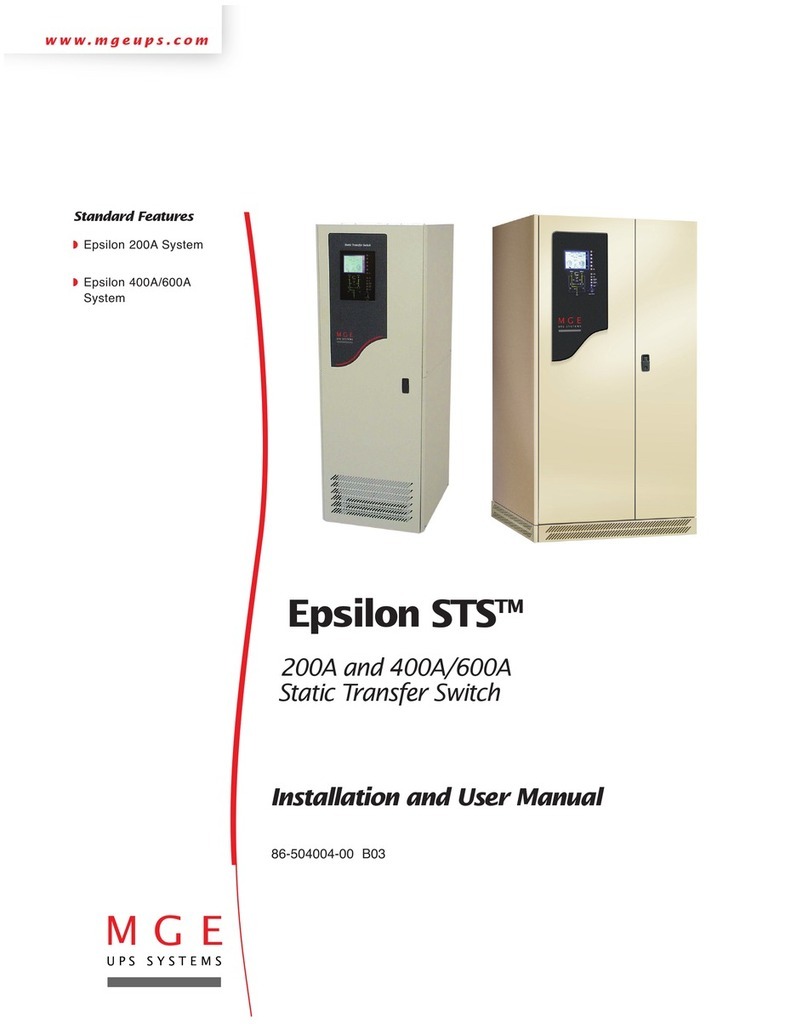
MGE UPS Systems Pulsar STS User manual

MGE UPS SYSTEMS - 5102761700/AC
THE MERLIN GERIN KNOW-HOW
Pulsar STS Système de transfert
de source
Manuel d'installation
et␣ d'utilisation
Source transfer
switch
Installation and user
manual
Nothing will stop you now
S1
S2
Pulsar STS

0MGE UPS SYSTEMS - 5102761700/AC
............................... i
Français ..................... 1
English ....................15
Deutsch ...................29
Italiano ....................43
Español....................57
Nederlands..............71

MGE UPS SYSTEMS - 5102761700/AC

0MGE UPS SYSTEMS - 5102761700/AC
5102761700/AC
MGE UPS SYSTEMS
140, Avenue Jean Kuntzmann
ZIRST - Montbonnot Saint Martin
38334 - ST ISMIER CEDEX-FRANCE
www.mgeups.com
Nothing will stop you now
Publication : MGE UPS SYSTEMS, 09/99.
S1
S2
Pulsar STS

i
5102761700/AC -MGE UPS SYSTEMS
Consignes de sécurité
L'installation et l'exploitation du module Pulsar
STS peuvent être réalisées par toute personne se
conformant aux indications portées dans le présent
manuel. Cependant, si vous rencontrez un
problème, nous vous recommandons de consulter
notre service après-vente.
Il est impératif de suivre les procédures
décrites. Leur non respect peut entraîner
des dangers pour les personnes,
occasionner des dommages et annuler la
garantie constructeur.
Toute opération de dépannage ou de
maintenance doit être effectuée par nos
services.
Pour plus de détails concernant les ASI, se référer
au "manuel d’installation et d’utilisation" fourni avec
les appareils.
Sicherheitshinweise
Die Installierung und die Nutzung des Pulsar STS-
kastens können von jeder Person vorgenommen
werden, die sich an die Anweisungen des
vorliegenden Handbuchs hält. Doch, sollte es
Probleme geben, setzen Sie sich bitte mit dem
MGE UPS SYSTEMS Kundendienst in
Verbindung.
Es ist wichtig, die Einzelschritte zu
befolgen. Ein Nichtbeachten kann zu
Gefährdung von Personen, Schäden an
der Anlage, sowie dem Verlust der
Herstellergarantie führen.
Arbeiten, die das Öffnen der Geräte
notwendig machen, dürfen nur von Elektro-
Fachpersonal durchgeführt werden.
Für weitergehende Informationen zur USV-
Anlagen möchten wir auf die Bedienungs- und
Installationsanleitung USV hinweisen.
Consegne di sicurezza
L'installazione e la gestione del modulo Pulsar
STS possono essere realizzate da qualsiasi
operatore che si conformi alle indicazioni riportate
nel presente manuale. Eppure, se incontrate
difficoltà, noi vi raccomandiamo di consultare il
nostro servizio assistenza dopo vendita.
E’ imperativo seguire rigorosamente le
procedure descritte.
Se non si rispettano queste procedure puo’
essere pericoloso per le persone,
cagionare danni ed annullare la garanzia
del costruttore.
Tutte le operazioni di riparazione o di
manutenzione devono essere effettuate
dai nostri servizi.
Per maggiori dettagli concernente le UPS, riferirsi
al "libretto d’installazione e d’istruzioni" fornito con
questi apparecchi.
Consignas de seguridad
Cualquier persona que se conforme a las
indicaciones establecidas en el presente manual
podrá realizar la instalación y la explotación del
módulo Pulsar STS. Si ocurre un problema al
poner en práctica los procedimientos descritos en
este manual, le recomendamos consultar nuestro
servicio de postventa.
Es imperativo respetar rigurosamente los
procedimientos descritos. No respetar
estos procedimientos puede acarrear
peligro para las vidas humanas, ocasionar
perjuicios y anular la garantía del
fabricante.
Toda operación de reparación o
mantenimiento debe ser efectuada por
nuestros servicios.
Para mayores detalles sobre los SAI, consultar el
"manual de instalación e instrucciones"
suministrado con los aparatos.
Regras de segurança
A instalação e a exporação da caica Pulsar STS
podem ser realizadas por qualquer pessoa que
cumpra as indicações mencionadas no presente
manual. Caso algum problema se apresente,
recomendamos consultar nosso serviçio apõs
venda. É imperativo que os procedimentos
descritos sejam seguidos rigorosamente.
O desrespeito dos mesmos procedimentos
pode ocasionar perigos para as pessoas,
causar avarias no aparelho, e anular a
garantia do fabricante.
Toda operação de conserto ou de
manutenção deve ser efetuada por nossos
serviços.
Para mais detalhes concernentes aos aparelhos,
referir-se ao "manual de instalação e de utilização"
fornecido com os aparelhos.
Safety guidelines
The Pulsar STS module can be installed and
operated by all persons following the instructions
given in this manual. However, if you encounter a
problem, we recommend that you contact our after-
sales support service.
It is imperative that the instructions be
followed strictly.
Not adhering to these instructions may
endanger personnel, result in damage and
render the manufacturer’s warranty void.
All repair or maintenance operations must
be carried out by our after-sales support
personnel.
For more information on the UPSs, please refer to
their "installation and user manual".

MGE UPS SYSTEMS - 5102761700/AC
ii
Veiligheidsvoorschriften
De Pulsar STS-kast kan worden geïnstalleerd en
bediend door elke persoon die de instructies in
deze handleiding strikt opvolgt. Indien u een
probleem, kunt u het beste contact opnemen met
onze service afdeling.
Het is noodzakelijk dat u de instructies
strikt opvolgt. Het niet opvolgen van deze
instructies kan het personeel in gevaar
brengen, resulteren in schade en de
garantie komt te vervallen.
Alle reparatie- en
onderhoudswerkzaamheden moeten
uitgevoerd worden door ons service
personeel.
Voor meer informatie betreffende de UPS, zie de
"installatie- en gebruikershandleiding".
Sikkerhedsforskrifter
Pulsar STS-boksen kan Installeres og bruges af
allepersoner, der følger instruktionerne i denne
manual. Pas på ! Skulle De støde på problemer, til
trods for at De har fulgt anvisningerne i vores
instruktionsbog, bør De henvende Dem til vores
kundeservice.
Det er absolut nødvendigt at følge
anvisningerne i instruktionsbogen.
Hvis De ikke overholder dem, risikerer De
at udsætte Deres personal for fare, at
apparatet bliver beskadiget, og at
garantien i så fald bordfalder.
Reparation og vedligeholdelse bør kun
foretages af vore teknikere.
Ønsker De mere detaillerede oplysninger
vedrørende apparatet, kan De finde dem i vores
instruktionsbog, som bliver leveret sammen med
apparatet.
Sikkerhedsforskrifter
Pulsar STS-boksen kan installeres og brukes av
alle personer som følger instruksjonene i denne
veiledningen. Dersom det oppstår problemer, bør
du ta kontakt med vår serviceavdeling.
Det er ytterst viktig at du følger
fremgangsmåten som er beskrevet i
håndboken, til punkt og prikke.
Operasjoner utført i strid med disse
retningslinjerne kan forårsake
personskader eller skader på apparatet og
annullere fabrikantens garanti.
Alle reparasjons-og vedlikeholdsinngrep
må utføres av vårt servicepersonale.
Trenger du flere opplysninger om apparatet, kan
du slå opp i "Håndbok for installering og bruk" som
følger med apparatet.
Säkerhetsföreskrifter
Pulsar STS-boxen kan installeras och användas
av alla som följer de instruktioner som ges i den
här manualen. Om Du stöter på problem,
rekommenderar vi att Du kontaktar vår
serviceverkstad.
Det är mycket viktigt att Du noggrant följer
instruktionerna i denna bruksanvisning.
Om instruktionerna inte följs kan materialet
skadas och bli farlig att använda.
Dessutom upphör tillverkarens garanti att
gälla.
Reparationer och underhåll får endast
utföras av kvalificerad fackman.
Mer utförlig information om materialet hittar Du i
bruksanvisningen för installation och användning.
Turvallisuusohjeet
Pulsar STS-yksikön voi asentaa ja sitä voivat
käyttää kaikki henkilöt tämän käyttöohjeen ohjeiden
mukaisesti. Jos törmäätte ongelmiin
seuratessanne käsikirjassa kuvattuja
toimintaohjeita, suosittelemme huoltopalvelumme
puoleen kääntymistä.
On ehdottoman tärkeää seurata tarkkaan
käsikirjassa kuvattuja toimintaohjeita.
Laiminlyönti saattaa aiheuttaa henkilölle
vaaratilanteen, laite voi vaurioitua ja
rakentajan takuu peruuntua.
Kaikki korjaus-ja huoltotoimet on
suoritettava oman henkilökuntamme
kautta.
Laite mukana tulevasta "asentamista ja käyttöä
käsittelevästä käsikirjasta" löydätte lisätietoja
laitteesta.

15
MGE UPS SYSTEMS - 5102761700/AC
Contents of package ................................ 16
Storage .................................................... 16
Recycling of packing ................................ 16
Function ................................................... 17
Characteristics ......................................... 17
Overall views............................................ 18
Setting the input voltage .......................... 20
Installation ................................................ 21
Cconnections ........................................... 22
Communication ........................................ 23
................................................................. 25
................................................................. 26
Glossary ................................................... 27
Index ........................................................ 27
Presentation
Contents
All MGE UPS SYSTEMS products are protected by patents. They implement original technology which is not available to other
competitors of MGE UPS SYSTEMS.
To take evolving standards and technology into account, the technical characteristics contained in this document are not
binding unless confirmed by MGE UPS SYSTEMS.
This document may be reproduced only with the consent of MGE UPS SYSTEMS. Authorised copies must be marked “MGE
UPS SYSTEMS Pulsar STS installation and user manual N°5102761700”.
Installation
Operation
Appendices
Troubleshooting

MGE UPS SYSTEMS - 5102761700/AC
16
Contents of package
The Pulsar STS package contains the
following (see figure 1):
◗Pulsar STS module,
◗installation and user manual
(this document),
◗four adhesive footpads,
◗four M6 bolts with four cage nuts,
◗two communications cables.
Storage
If the Pulsar STS module is stored prior to
installation, it should remain in the original
packing in a dry place (storage temperature
range: –40°C to +70°C).
Recycling of packing
Packing materials must be disposed of in
compliance with applicable laws and
regulations.
Presentation
Fig. 1
Manuel d'installation et
d'utilisation
Installation and user
manual
LE SAVOIRFAIRE MERLIN GERIN
MultiSlot
Expansion module
for communication
cards
Module d'extension
pour cartes de
communication
Pulsar STS S1
S2
www.mgeups.com

17
MGE UPS SYSTEMS - 5102761700/AC
Function
MGE UPS SYSTEMS developed
Pulsar STS to guarantee the uninterrupted
operation of your sensitive equipment. The
Pulsar STS source transfer switch is a
simple and effective solution to manage the
redundancy provided by two independent
power sources.
Pulsar STS handles the automatic or
manual transfer of your loads between two
independent power sources without
interrupting the supply of power (< 6
milliseconds). Either of the two sources may
be designated as the preferred source with
the other becoming the alternate source. In
the event of a failure, transfer from one to
the other is automatic and instantaneous.
Automatic transfer to the alternate source
takes place if the voltage of the preferred
source goes outside a tolerance of 12%
above or below the nominal value. Return to
the preferred source is automatic when the
voltage returns within the ±12% tolerance
range.
To provide a maximum level of protection for
the connected sensitive equipment, both
power sources should be UPSs (on-line or
off-line) providing a sinusoidal output.
However, the Pulsar STS module can also
be supplied by one UPS and another type of
source (AC system, engine generator set,
etc.), or by two non-UPS sources.
Characteristics
The Pulsar STS module has the following
characteristics:
◗208 / 220 / 230 / 240V versions (input
voltage): Pulsar STS 10 and
Pulsar STS 16,
◗120 V version (input voltage):
Pulsar STS 1400,
◗input current: 10A (Pulsar STS 10),16A
(Pulsar STS 16), 12A (Pulsar STS 1400),
◗protection by thermal circuit breakers
(10A, 16A or 12A depending on the version),
◗threshold before transfer from preferred to
alternate source: ±12%,
◗maximum operating temperature: 35°C,
◗dimensions: 1U x 19 inches (44.45 mm x
482.6 mm);
◗weight: 5 kg.

MGE UPS SYSTEMS - 5102761700/AC
18
Overall views
Figure 2 shows in detail the front and rear
panels of the various Pulsar STS versions.
Key to figure 2:
1voltage indication LEDs for the two
power sources S1 and S2:
green LED: voltage OK, within tolerances,
red LED: voltage NOK, outside ±12%
tolerances,
2button used to select the preferred
source:
: source S1 is the preferred source,
: source S2 is the preferred source,
3status LEDs for the source currently
supplying power:
OFF: source not used.
green: preferred source supplying power,
yellow: alternate source supplying power,
Note: only one of these LEDs is ON at a
time,
4 red LED indicating a Pulsar STS fault,
5 buzzer OFF pushbutton,
6 buzzer,
7 connection cables between the module
and the two power sources S1 and S2,
8 connection sockets for the sensitive
equipment.
◗Pulsar STS 10 and Pulsar STS 16:
8 IEC-type sockets,
◗Pulsar STS 1400: 6 NEMA-type sockets,
9 output protection circuit breakers on
Pulsar STS 16,
10 SUB-D 9-pin connector, for
communication (UPS S1 type) from source 1,
11 SUB-D 9-pin connector, for
communication (UPS S2 type) from source 2,
12 SUB-D 9-pin connector, for outgoing
communication (Basic type),
13 SUB-D 9-pin connector, for outgoing
communication (STS COM type, i.e. dry
contacts),
14 Pulsar STS input voltage selector
(European versions),
15 protection circuit breakers on the inputs
from the two sources.

19
MGE UPS SYSTEMS - 5102761700/AC
Fig. 2 : front and rear panels of the Pulsar STS modules
Pulsar STS S1
S2
1 32 4 5 6
7
Pulsar STS 10
Pulsar STS 16
Pulsar STS 1400
www.mgeups.com
8 8
15
Pulsar STS 1400
1210
11 13
S2
S1
8 8 14
15
Pulsar STS 10
1210
1311
7
S2
S1
8 8 149
15
Pulsar STS 16
10 12
11 13
7
S2
S1
14 7

MGE UPS SYSTEMS - 5102761700/AC
20
Installation
Setting the input
voltage
Before making any connections, make sure
that the sources selected to supply the
Pulsar STS are compatible with its
characteristics.
Pulsar STS 10 and Pulsar STS 16: 208V -
220V - 230V - 240V.
Pulsar STS 1400: 120V.
The factory input voltage setting for Pulsar
STS 10 and Pulsar STS 16 is 230V. If
necessary, set the voltage to another value
(208V, 220V, 230V or 240V) using the
voltage selector 14 (see figure 3).
In the event of an electrical fault, a circuit
breaker on each of the source inputs
protects the Pulsar STS module.
The voltage selector 14 may be
used only when the Pulsar STS
module is de-energized, i.e. power
cables 7not connected to the
sources.
Once the module has been correctly set up,
connect the two power cables 7to the two
sources.
230V input
voltage
240V input
voltage
208V input
voltage
220V input
voltage
Fig. 3
14
7
1 2 3 4 5 6 7 81 2 3 4 5 6 7 8
1 2 3 4 5 6 7 8 1 2 3 4 5 6 7 8

21
MGE UPS SYSTEMS - 5102761700/AC
Installation
Rack mounting
Figure 4 shows how to install the Pulsar
STS module in a 19-inch bay using the four
M6 bolts and the cage nuts positioned at the
desired height in the cabinet uprights.
The module is not as wide as the bay and
therefore does not obstruct the flow of air.
If the temperature inside the bay can
rise above 35°C, ventilation is
required. If this is not possible, the
Pulsar STS module should be
installed outside the bay.
On a flat surface
Figure 5 shows how to attach the adhesive
footpads under the Pulsar STS module for
installation on a flat surface.
Fig. 5
Fig. 4
Pulsar STS S1
S2 www.mgeups.com
Pulsar STS S1
S2
www.mgeups.com

MGE UPS SYSTEMS - 5102761700/AC
22
Connections
Connect the power cables 7to the two
electrical sources (S1 and S2) supplying
Pulsar STS.
Connection to UPSs
Connect the power cables 7to one of the
output sockets on each UPS.
Pulsar STS is energized as soon as one of
the sources (S1 or S2) is in operation.
Fig. 6
to the sensitive
equipment supplied
by Pulsar STS
Pulsar STS 10A
8
Basic
T 6.3A
250V~
Ue/In/Eing
Amp: 25A
Volt: 38Vdc
I max 4.3A
Us/Out/Ausg
UPS S2
Basic
T 6.3A
250V~
Ue/In/Eing
Amp: 25A
Volt: 38Vdc
I max 4.3A
Us/Out/Ausg
UPS S1
8
7
S2 S1

23
MGE UPS SYSTEMS - 5102761700/AC
Communication
Use of the communications ports on the
Pulsar STS module is optional and not
required for correct operation of the module.
Pulsar STS is equipped as standard with a
Basic communications port for incoming
data from both sources S1 and S2 (both
UPSs must have a free Basic port), as well
as with an STS COM communications port.
Basic communication
For a High Availability Pack configuration,
the Basic Pulsar STS communications port
receives the data from both UPS sources S1
and S2. To activate the port, it is necessary
to connect the UPS S1 and UPS S2
communications ports on the module to the
Basic communications ports on the UPSs S1
and S2, using the cables supplied with
Pulsar STS (see figure 7).
The Basic port of the Pulsar STS always
forwards the status information provided by
the Basic port of the UPS currently supplying
the equipment.
Fig. 7
Basic
T 6.3A
250V~
Ue/In/Eing
Amp: 25A
Volt: 38Vdc
I max 4.3A
Us/Out/Ausg
Pulsar STS 10A
Basic
T 6.3A
250V~
Ue/In/Eing
Amp: 25A
Volt: 38Vdc
I max 4.3A
Us/Out/Ausg
UPS S1
UPS S2 Basic
11 12
10
Basic S2
Basic S1

MGE UPS SYSTEMS - 5102761700/AC
24
Fig. 8
The pin-out of the Basic Pulsar STS port
12 is the following:
◗pin 1 – frame earth,
◗pin 4 – normal operation,
◗pin 5 – common,
◗pin 6 – operation on bypass,
◗pin 7 – low battery shutdown warning,
◗pin 8 – operation on inverter,
◗pin 9 – operation on battery.
Fig. 10
Fig. 9
12
NO
NC NO NONO
54321
9876
common
UPS with "Protocol
Interface" (option)
This option converts Basic type information
into the RS232 serial protocol. It is then
possible to use the administration and
system shutdown capabilities of Solution
Pac software.
Pulsar STS
STS COM
13
Breaking capacity of relays:
V max = 30 V
I max = 100 mA
NO = normally open,
NC = normally closed.
MultiSlot (optional)
When the MultiSlot option is installed, the
Pulsar STS and the two UPSs act as a one.
MultiSlot, equipped with two MetaUPS
acquisition cards, concentrates the data
coming from the U-Talk ports on the UPSs
and from the STS COM port on Pulsar STS.
Communication with the protected systems
is optimized through use of a U-Talk, J-Bus
or SNMP card.
In this case, the protected application will
shutdown only when all available energy has
disappeared, i.e. the batteries on both UPSs
have been depleted. See the MultiSlot user
manual for information on connections.
STS COM communication
This communications port 13 supplies
status information on Pulsar STS.
Pin-out of the STS COM port:
◗pin 1 – frame earth,
◗pin 4 – source S2 preferred,
◗pin 5 – common,
◗pin 6 – source S1 within tolerances,
◗pin 7 – source S2 within tolerances,
◗pin 8 – no fault in Pulsar STS,
◗pin 9 – source S1 preferred.
13
NO
NC NO NONO
54321
9876
common

25
MGE UPS SYSTEMS - 5102761700/AC
Operation
1
S1
S2
2 3 4 5 6
It is assumed here that source S1 is the
preferred source (button 2in the up
position).
The LEDs 1indicate the voltage status of
the sources S1 and S2.
◗green indicates that the voltage is within
tolerances (±12% of the rated voltage).
◗red indicates that the voltage is outside
tolerances.
The LEDs 3 indicate the operating status
of the sources S1 and S2.
◗OFF: source not used.
◗green: preferred source supplying power.
◗yellow: alternate source supplying power.
The applications are supplied with power if
either of the two LEDs is ON.
LED 4is red if an internal fault has
occurred in the Pulsar STS module. Contact
the MGE UPS SYSTEMS after-sales
technical support.
In addition to the LEDs, the buzzer 6
sounds in the following events:
◗source S1 or source S2 outside
tolerances;
◗internal fault in the Pulsar STS module.
Once the problem has been identified, the
buzzer may be turned off by pressing button
5 .
Note: to make source S2 the priority source
(for example, if maintenance is required on
source S1), simply press button 2 .
Fig. 11
Fig. 12
AC
source
rectifier
battery
inverter
to the
sensitive
equipment
AC
source
rectifier
battery
inverter
UPS S1
UPS S2
Pulsar STS
S1
S2

MGE UPS SYSTEMS - 5102761700/AC
26
Troubleshooting
All LEDs on the front panel of the Pulsar
STS are OFF. The power sources S1 and S2 are absent.
One of the voltage-status LEDs 1for the
sources is red.
The red fault LED 4is OFF.
The corresponding power source is absent
or outside tolerances.
On Pulsar STS 16, the two voltage-status
LEDs 1for the sources are green.
The red fault LED 4is OFF and the
application is not supplied with power.
There is an overload on the output circuits.
Check power sources S1 and S2.
Reset the circuit breakers 15 on the rear
panel of Pulsar STS (if the fault has been
cleared).
Check the concerned power source. Reset
the circuit breaker 15 on the rear panel of
Pulsar STS.
Reset the circuit breaker 9.
Front-panel display Problem Solution
The red fault LED 4is ON. Internal fault in Pulsar STS.Contact the after-sales technical support.

27
MGE UPS SYSTEMS - 5102761700/AC
Appendices
Index
Adhesive footpads: 21,
Bay (installation): 21,
Buzzer (operation and reset): 18, 25,
Circuit breakers (reset): 18, 26,
Communications pin-outs: 24,
Contents of module: 16,
Input voltage selector: 18, 20,
LEDs (meaning): 18, 25,
Packing: 16,
Power supply (characteristics): 17,
Selection of preferred source: 18, 25,
UPS: 17, 22,
Warnings ( ): i, 15.
Glossary
Alternate source: power source S1 or S2
for Pulsar STS module, selected as
alternate using button 2,
Basic: data exchange protocol for status
information on sources S1 and S2,
Operation on bypass: source S1 or S2
supplying power directly from their AC
source,
Operation on inverter: source S1 or S2
supplying protected, quality power via their
inverter,
Preferred source: power source S1 or S2
for Pulsar STS module, selected as
preferred using button 2,
Selector: set of eight DIP switches used to
select the input voltage for the Pulsar STS
module,
Sensitive equipment: devices supplied and
protected by the Pulsar STS module,
STS COM: data exchange protocol for
status information on the Pulsar STS
module, via dry contacts,
SUB-D 9-pin connector: connector with
nine pins, used for communications signals,
UPS: uninterruptible power supply.

MGE UPS SYSTEMS - 5102761700/AC
28
Table of contents
Languages:
Other MGE UPS Systems Switch manuals
Popular Switch manuals by other brands

DeviceWell
DeviceWell HDS7106 user manual

Helwett Packard
Helwett Packard 5140 Disassembly instructions
TRENDnet
TRENDnet TPE-TG44G Quick installation guide
DCN
DCN S4600-10P-SI manual

CNET
CNET CGS-500E Specifications
Omnitron Systems Technology
Omnitron Systems Technology OmniConverter 10GPoE+/Sx user manual
