MGL Avionics Vega TP-3 User manual
Other MGL Avionics Avionic Display manuals
MGL Avionics
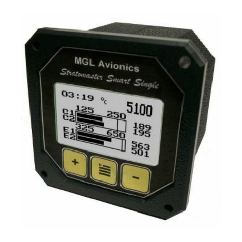
MGL Avionics Stratomaster Smart Single EMS-503 User manual
MGL Avionics
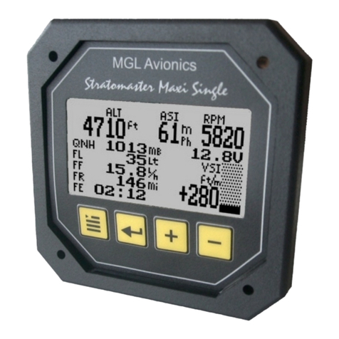
MGL Avionics Stratomaster Maxi Single Flight II User manual
MGL Avionics
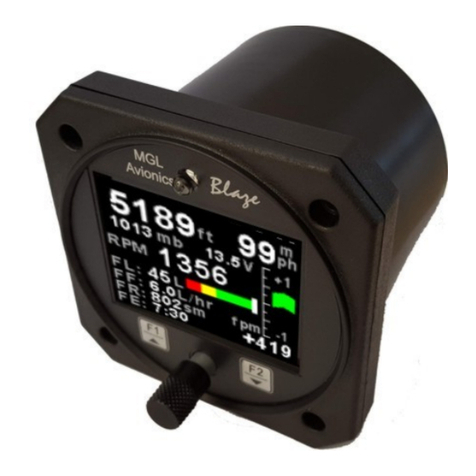
MGL Avionics Blaze FLIGHT-3 User manual
MGL Avionics
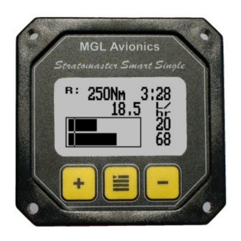
MGL Avionics FF-1 User manual
MGL Avionics
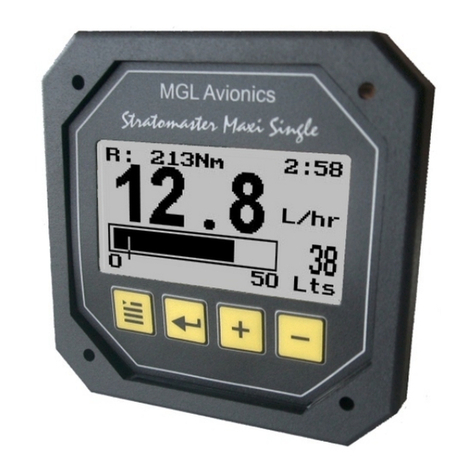
MGL Avionics Stratomaster Maxi Single FF-3 User manual
MGL Avionics
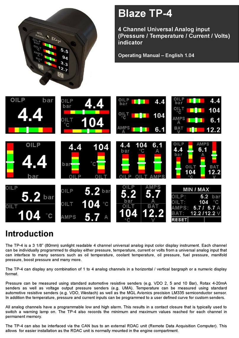
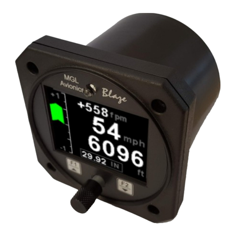
MGL Avionics Blaze TP-4 User manual
MGL Avionics
MGL Avionics Blaze ASV-2 User manual
MGL Avionics
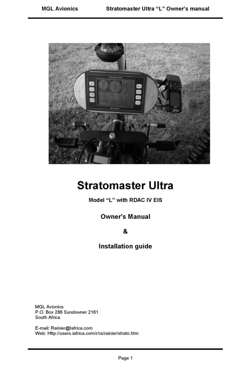
MGL Avionics Stratomaster Ultra L Troubleshooting guide
MGL Avionics
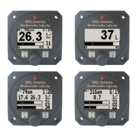
MGL Avionics FF-1 User manual
MGL Avionics
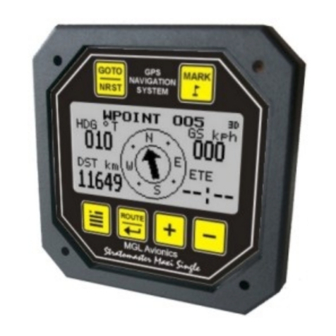
MGL Avionics Stratomaster Maxi Singles GPS-1 User manual
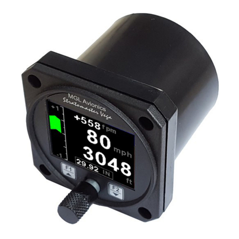
MGL Avionics
MGL Avionics Vega ASV-1 User manual
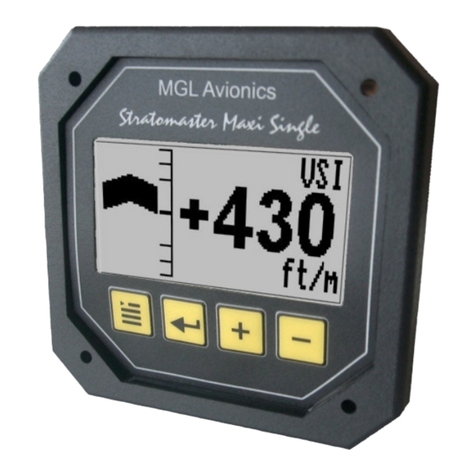
MGL Avionics
MGL Avionics Stratomaster Maxi Single VSI-2 User manual
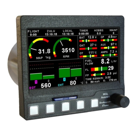
MGL Avionics
MGL Avionics XTreme - EMS User manual
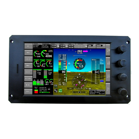
MGL Avionics
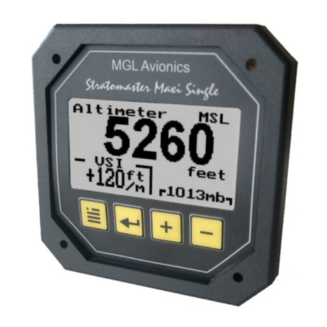
MGL Avionics iEFIS Lite User manual
MGL Avionics
MGL Avionics Stratomaster Maxi Single ALT-3 User manual
MGL Avionics
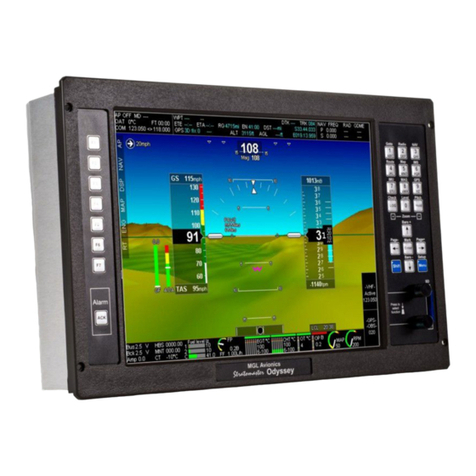
MGL Avionics EFIS G2 User manual
MGL Avionics
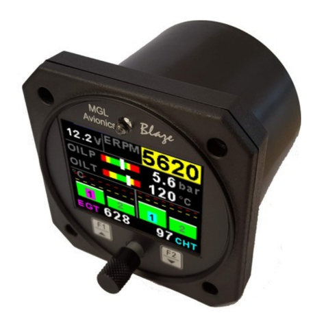
MGL Avionics Blaze EMS-2 User manual
MGL Avionics
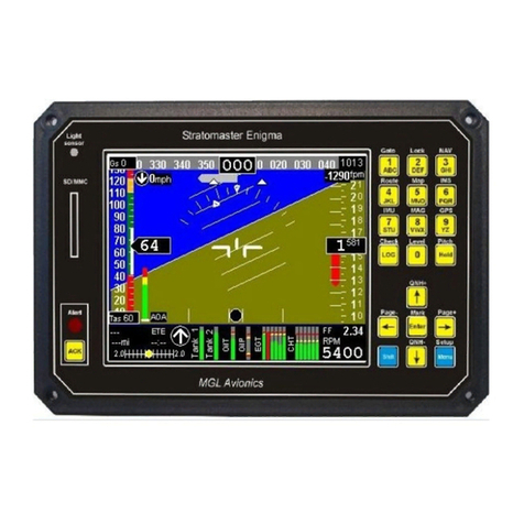
MGL Avionics Stratomaster Enigma User manual
MGL Avionics
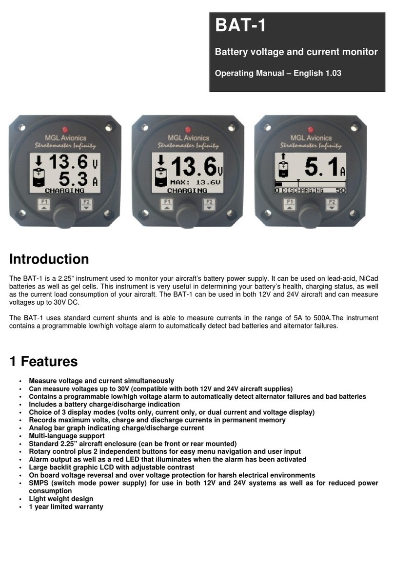
MGL Avionics BAT-1 User manual
MGL Avionics
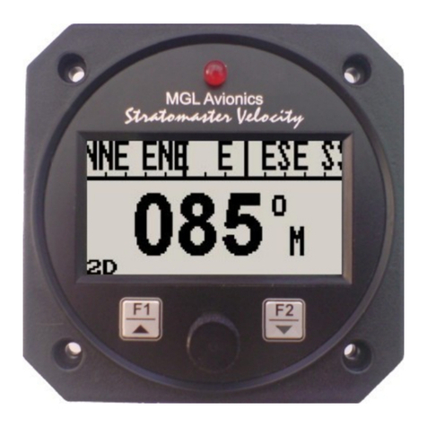
MGL Avionics AV-2 User manual
Popular Avionic Display manuals by other brands
Smart Avionics
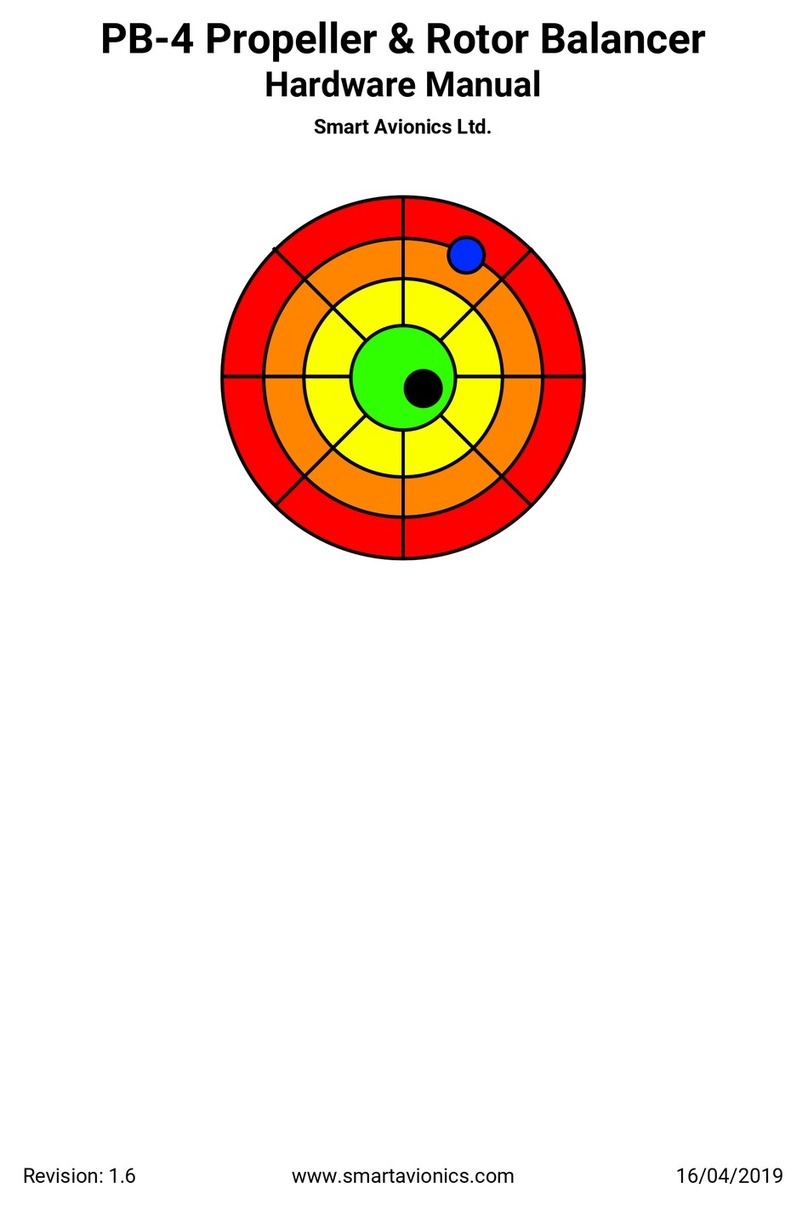
Smart Avionics PB-4 Hardware manual
Midcontinent
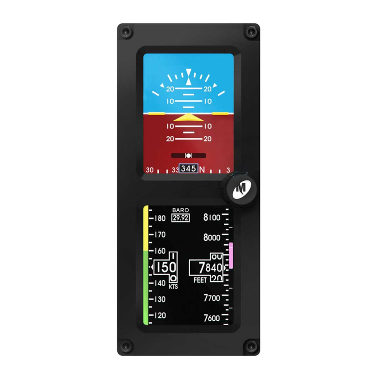
Midcontinent SAM MD302 pilot's guide
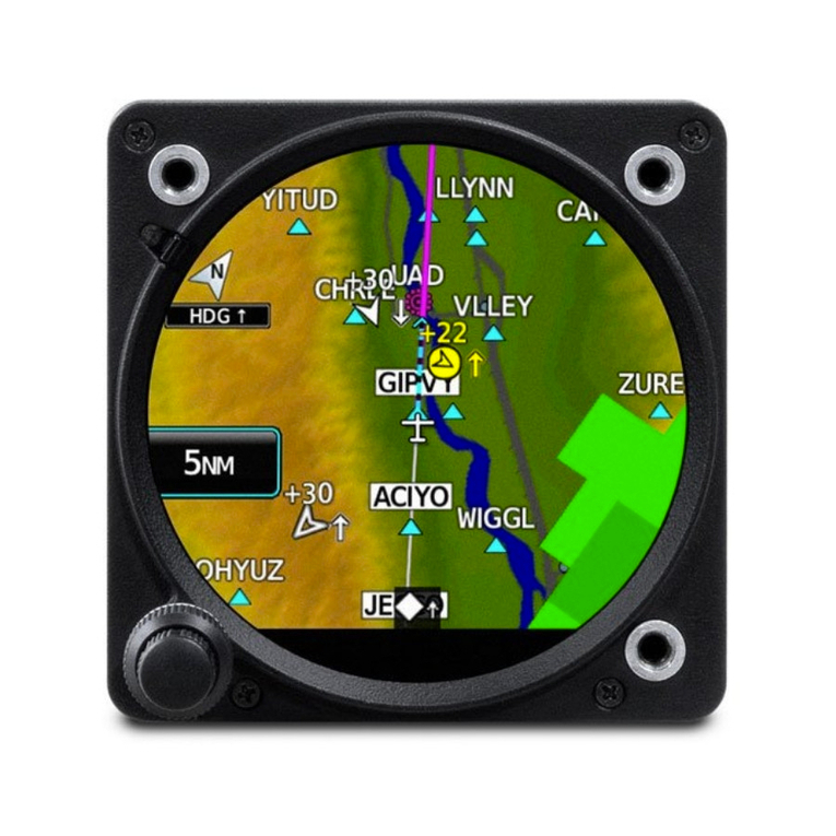
Garmin
Garmin GI 275 installation manual
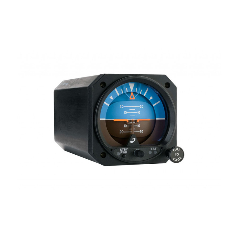
Mid-Continent Instruments
Mid-Continent Instruments 4300 Series pilot's guide
Avidyne
Avidyne 700-00182 Series Instructions for Continued Airworthiness
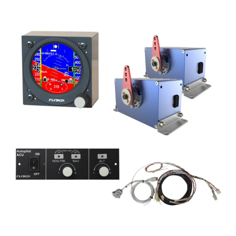
Flybox
Flybox Oblo manual
