5. Technical Data ThermiStar L .. SP 01/03/10
20
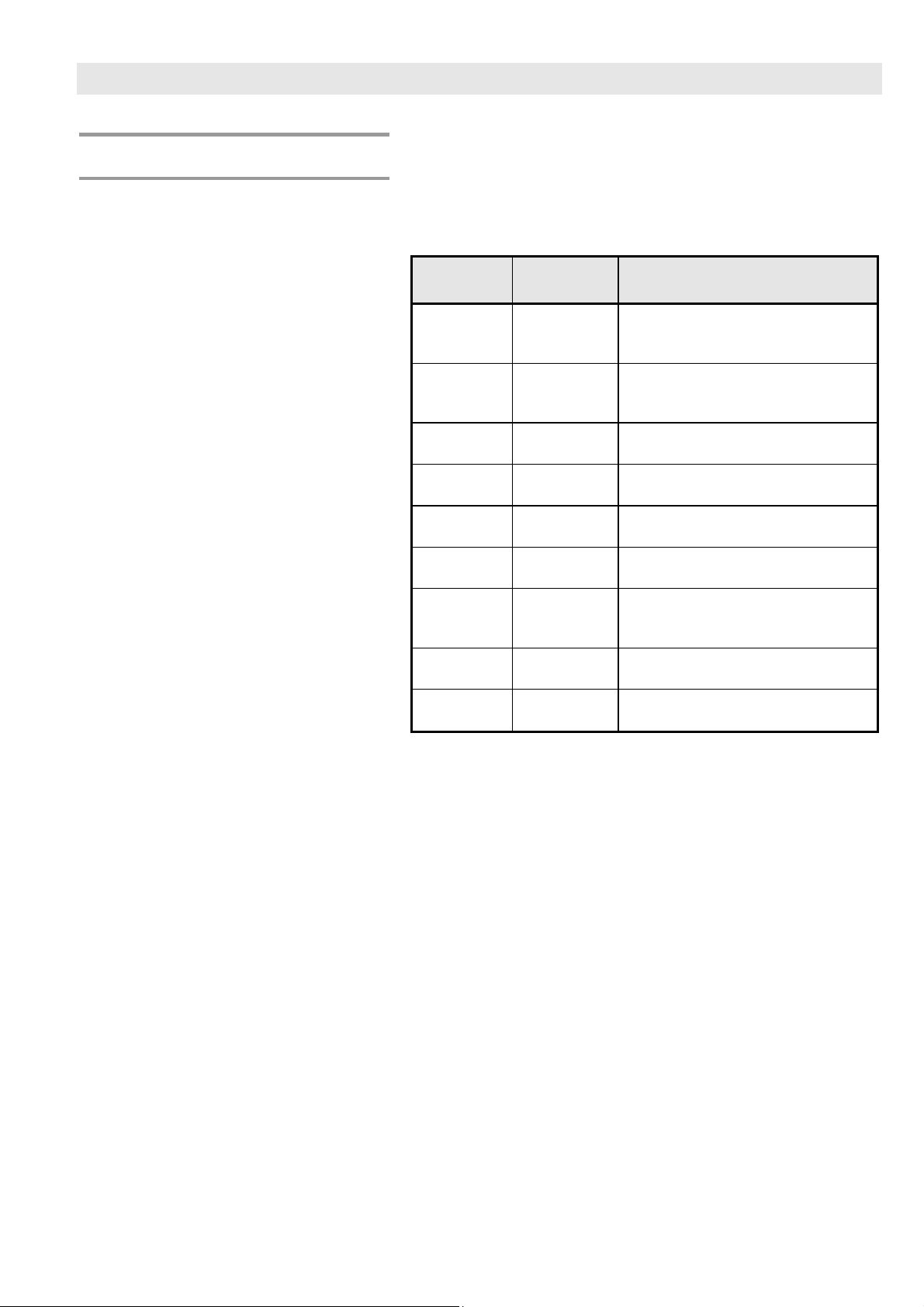
5.3 Technical data
Air/water heat pumps* Thermistar L 05 SP to L 41 SP
ThermiStar L .. 05 SP 07 SP 10 SP 13 SP 15 SP 19 SP 28 SP 34 SP 41 SP
Output A2/W35* Nominal heating
capacity kW 5,2 7,1 10,4 13,0 15,3 19,4 27,4 33,6 40,9
Power consumption condenser kW 1,3 1,7 2,4 3,0 3,5 4,8 6,4 7,9 9,6
Cooling capacity kW 4,0 5,6 8,1 10,0 12,0 14,9 21,3 26,1 31,8
Performance no. COP 3,7 3,9 4,0 3,7 4,0 3,9
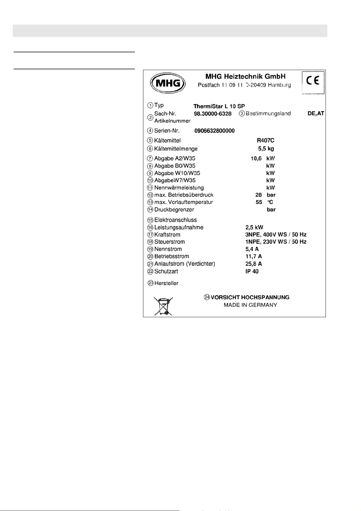
Refrigerant R 407 c for hot water temperatures up to 55°C
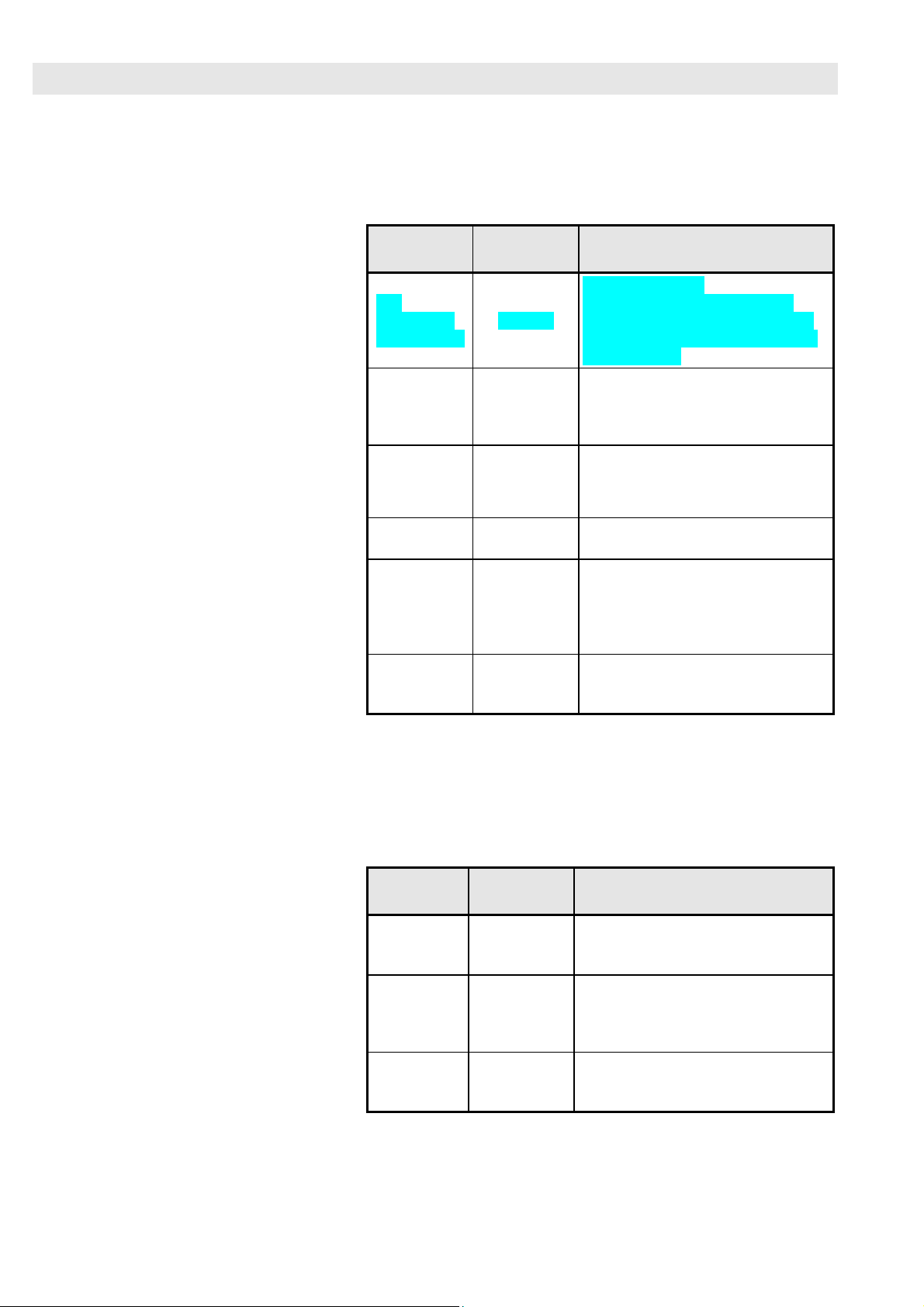
Refrigerant dosage
for max. 20 m line length** kg 3,5 4,2 5,5 8,5 10,0 12,0 15,5 20,2 20,7
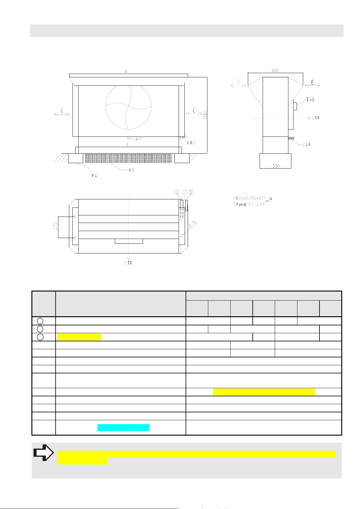
Refrigerant lines Liquid (1) mm 10 12 15 18 22
Suction gas (2) 15 22 28 35 42
Thawing (3) 10 12 15 18
Nominal current consumption A 3,0 4,0 5,4 6,5 7,4 12,6 14,3 16,2 18,6
Operating current, max. A 5,0 5,2 8,2 10,1 11,8 16,0 21,0 25,0 32,0
Starting current with soft-start A 13,0 20,0 25,8 32,0 37,0 49,5 63,5 83,5 99,0
Blocked rotor current A 26,0 40,0 51,5 64,0 74,0 99,0 127,0 167,0 198,0
Power circuit breaker / Automatic
circuit breaker, slow A 3x10 3x16 3x20 3x25 3x32 3x40 3x63
Recommended wire gauge mm² 1,5 2,5 4,0 6,0 10,0
Electrical connection
Compressor
Control current
3NPE, 400 V
1NPE, 230 V
Protection class heat pump IP 40 (according to EN 60529)
Protection class split evaporator IP 54 (according to EN 60529)
Evaporated air flow rate, nominal m³/h 2645 2570 3330 5220 5220 6670 10820 16010 14800
Sound pressure at 5 m dB(A) 32 32 38 35 35 41 43 53 53
Mass flow heating system nomi-
nal kg/h 900 1220 1790 2240 2630 3340 4700 5780 6900
Pressure loss heating water at
nominal flow rate kPa 3,0 3,4 4,7 5,3 5,8 3,2 4,5 4,2 5,2
Heating connection ET“ 1 1½
Outside dimensions WxDxH in-
ner part mm 690x600x900 1030x730x900
Outside dimensions WxDxH
outer part mm 1230x880x1030 2155x880x1030 3080x880x1030
Weight of inner part kg 107 120 140 160 175 200 207 217 225
Weight of outer part kg 66 73 80 138 152 202 223
* Heating capacity and COP at A2/W35 as well as source side 3 K and heating side 10 K spread
** When changes to refrigerant lines lead to lengths exceeding 20 m, refrigerant dosage will change as follows:
Pipe with max. Ø 22 mm +/- 100 g/m, pipe with max. Ø 28 mm +/- 150 g/m, pipe with max. Ø 35 mm +/- 200 g/m
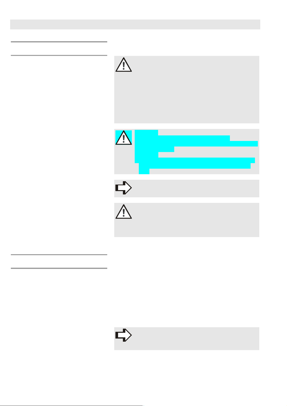
NOTE!
Refrigerant R407C for heating water temperatures up to H55°C.