Salda SIG 6-17 Manual

Subject to technical modi•cation
SIG 6-17
BRINE-WATER HEAT PUMPS
INSTALLATION AND MAINTENANCE MANUAL

2
SIG 6-17
www.salda.lt
TABLE OF CONTENTS
1.BasicInformation...........................................................................................................3
1.1. Safety Notes.............................................................................................................3
1.2 Intended Use.............................................................................................................3
1.3. Legal Provisions and Guidelines.............................................................................3
1.4. Legal Guidelines, Rules, Warranty Terms, Receiving Inspection.............................3
1.4.1. General information............................................................................................3
1.4.2. Legal Guidelines and Rules...............................................................................3
1.4.3. Receiving Inspection..........................................................................................4
1.5. Energy-Ef!cient Use of the Heat Pump..........................................................4
2.BaselineUnit..................................................................................................................4
2.1. Application and main information..............................................................................4
2.2. Principle of Operation................................................................................................4
2.3. Main components......................................................................................................5
3. Transport.......................................................................................................................5
4. Installation.....................................................................................................................6
4.1. General information..................................................................................................6
4.1.1 Place for instalation............................................................................................6
4.1.2. Acoustic Emissions............................................................................................6
4.2. Heating System Connetion........................................................................................6
4.3. Heat Source Connection...........................................................................................7
4.3.1.Filling and venting the collector system..............................................................8
4.4. Electrical, Probes and Other Components Connections..........................................8
5. Start - up......................................................................................................................10
6. Maintenance and cleaning........................................................................................10
6.1. Cleaning the Heating System..................................................................................10
6.2. Cleaning the Heat Source System...........................................................................11
6.3. Sight glass inspection..............................................................................................11
7.Faults/Trouble-Shooting.............................................................................................11
8.Decommissioning/Disposal.......................................................................................12
9.DeviceInformation.......................................................................................................12
10.Appendix....................................................................................................................13
10.1. Dimension Drawings.............................................................................................13
10.2. Diagrams...............................................................................................................14
SIG 6 (400).................................................................................................................14
SIG 8 (400).................................................................................................................15
SIG 10 (400)...............................................................................................................16
SIG 12 (400)...............................................................................................................17
SIG 14 (400)...............................................................................................................18
SIG 17 (400)...............................................................................................................19
10.3. Circuit Diagrams....................................................................................................20
10.4. Plumbing Diagram.................................................................................................24
10.5. Declaration of Conformity......................................................................................28

3
SIG 6-17
www.salda.lt
• Setup, installation, con!guration, and initial start up of the heat pump system must be carried out by a quali!ed tech-
nician applying the relevant statutory rules, regulations, and guide- lines, as well as the operating instructions.
• The use of the heat pump must be reported to the local utility or electric company.
• Any work on the heat pump may only be performed by an authorized and quali!ed customer service.
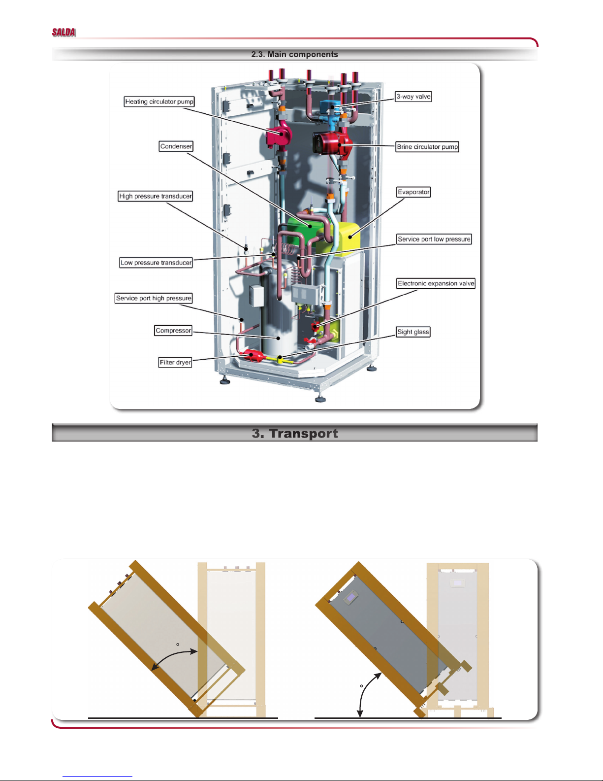
• The heat pump must not be tilted more than max. 45° (in either direction).
• Avoid exposing the heat pump to any type of moisture or humidity.
• Protect the heat pump from damage and dirt during all construction phases
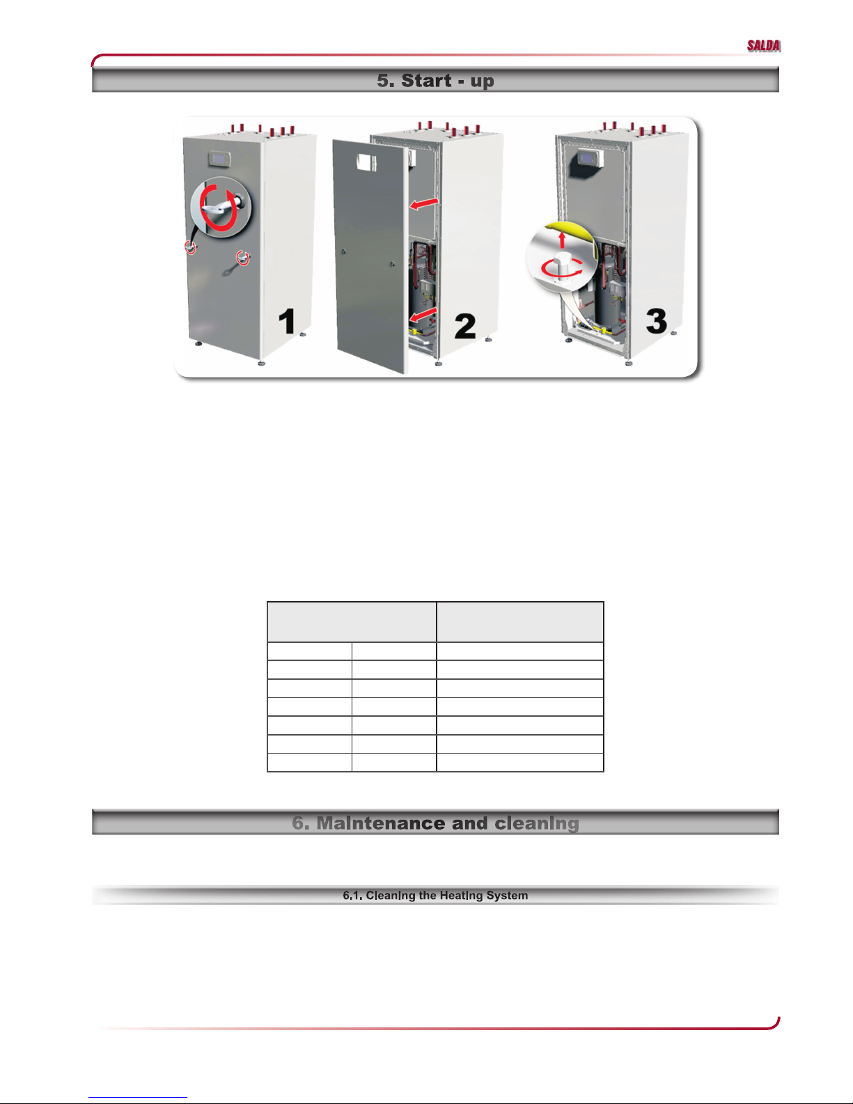
• The transport securing devices must be removed prior to commissioning.
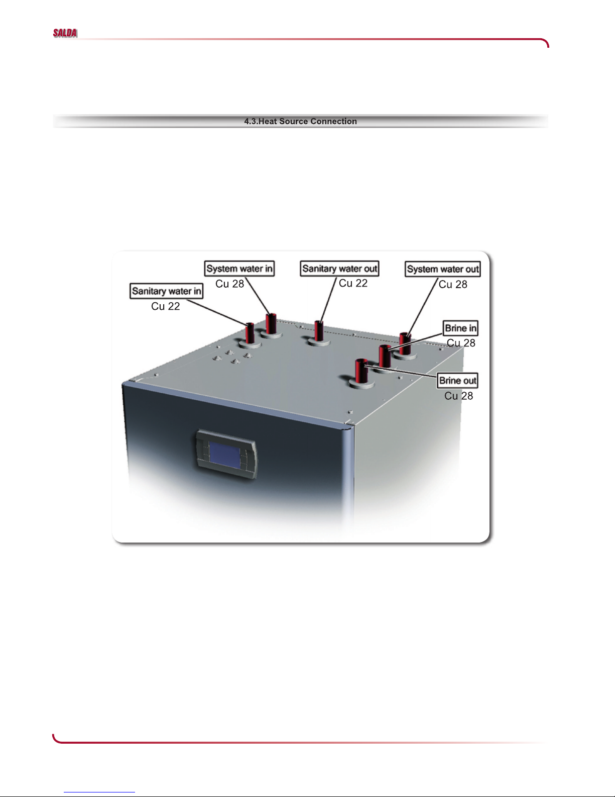
• The heating system must be "ushed prior to connecting the heat pump.
• The strainer must be !tted in the heat source inlet of the heat pump in order to protect the evaporator against the
ingress of impurities
• The brine solution must contain at least 25 % of an antifreeze agent on a mono-ethylene glycol or propylene glycol
basis and must be mixed prior to !lling.
• The clockwise phase sequence must be observed when connecting the load lines (the heat pump will deliver no out-
put and will be very noisy when the phase sequence is incorrect).
• To prevent the accumulation of deposits (e.g. rust) we recommend using a suitable corrosion protection system.
• Disconnect all electrical circuits from the power supply before opening the enclosure.
• Components and piping of the cooling circuit may never be used for transport.
• All work on the cooling circuit must be carried out by trained technicians who must be familiar with and trained in the
use and handling of the coolant.
• Never use harsh, abrasive, acidic or chlorine-containing cleansers on the surface of the equipment.
This device is only intended for use as speci!ed by the manufacturer. Any other use beyond that intended by the
manufacturer is prohibited. This requires the user to abide by the manufacturers product information. Please refrain
from tampering with or altering the device.
This heat pump is designed for use in a domestic environment according to Article 1, Paragraph 2 k) of EC direc-
tive 2006/42/EC (machinery directive) and is thus subject to the requirements of EC directive 2006/95/EC (low-voltage
directive). It is thus also intended for use by non-professionals for heating shops, of!ces and other similar working
environments, in agricultural establishments and in hotels, guest houses and similar / other residential buildings.
This heat pump conforms to all relevant DIN/VDE regulations and EU directives. For details refer to the EC Declara-
tion of Con formity in the appendix.
The electrical connection of the heat pump must be performed according to and conforming with all relevant VDE,
EN and IEC standards. Beyond that, the connection requirements of the local utility companies have to be observed.
The heat pump is to be connected to the heat source and heat distribution systems in accordance with all applicable
provisions.
Persons, especially children, who are not capable of operating the device safely due to their physical, sensory or
mental abilities or due to their inexperience or lack of knowledge, must not operate this device without supervision or
instruction by the person in charge.
Children must be supervised to ensure that they do not play with the device.
These operating instructions serve the correct installation, adjustment, and maintenance of the equipment.
The following information must therefore be read carefully and the heat pump must be installed, inspected, and
maintained by correspondingly trained technicians.
The manufacturer is not liable for mechanical, hydraulic, or electrical modi!cations after the warranty expires. The
warranty becomes null and void in case of not explicitly authorized actions carried out contrary to or in violation of
these operating instructions.
All applicable safety standards must be observed during installation. Check whether the properties of the power
supply system match those of the heat pump (type plate).
These operating instructions and the electrical scheme (diagram) of the heat pump must be stored carefully and
made available to the operating personnel if needed.
All guidelines based on CE standards were observed during design and manufacture of the heat pump. (See CE
Conformity Declaration (page 28)).
Compliance with the corresponding SEV, EN, and IEC standards is required for the electrical connection of the heat
pump. The connection speci!cations of the local utility or electric company must be complied with as well.

4
SIG 6-17
www.salda.lt
Our warranty does not cover damages caused by or due to the following reasons:
• Unsuitable or improper use or operation;
• Incorrect setup, adjustment, or incorrect initial startup by buyer or third parties;
• Installation of third party parts;
• Operating the equipment under overpressure or in excess of the speci!cations indicated by the factory;
• Noncompliance with the notes and information of the operating instructions.
The heat pumps have a warranty period of 24 months after the day of delivery. The sales, delivery, and war-
ranty terms and conditions according to the order con!rmation apply in all other instances.
The equipment is shipped on a wooden pallet and a corresponding protective cover. The equipment must be
checked for completeness and transport damage upon receipt.
If damages are detected, the corresponding damage must be noted immediately on the shipping document
and identi!ed with the following phrase: “Conditional acceptance due to obvious damage.”
By operating this heat pump you contribute to the protection of our environment. A prerequisite for an ef!cient op-
eration is the proper design and sizing of the heating system and the heat source system. In particular, it is important
to keep water "ow temperatures as low as possible. All energy consumers connected should therefore be suitable
for low "ow temperatures. A 1 K higher heating water temperature corresponds to an increase in power consumption
of approx. 2.5 %. Low-temperature heating systems with "ow temperatures between 30 °C and 40 °C are optimally
suited for energy-ef!cient operation.
The brine-to-water heat pump is to be used exclusively for the heating of heating water. It can be used in new or
previously existing heating systems. Brine is used as the heat transfer medium in the heat source system. Borehole
heat exchangers, ground heat collectors or similar systems can be used as the heat source.
The basic device consists of a ready-to-use heat pump for indoor installation, complete with sheet metal casing,
control panel and integrated heat pump manager. The refrigerant circuit is hermetically sealed. It contains the Kyoto
protocol approved refrigerant R407C with a GWP value of 1610.It is CFC-free, does not deplete ozone and is non-
"ammable.
All components required for the operation of the heat pump are located in the control box. A sensor for the external
temperature including mounting hardware supplied with the heat pump. The voltage supply for the load and control
current must be provided by the customer.
The heat generated by the sun, wind and rain is stored in the ground. This heat stored in the ground is collected at
low temperature by the brine circulating in the ground collector, ground coil or similar device.
A circulating pump then conveys the warmed brine to the evaporator of the heat pump. There, the heat is given off
to the refrigerant in the refrigeration cycle. When so doing, the brine cools so that it can again take up heat energy in
the brine circuit.
The refrigerant is drawn in by the electrically driven compressor, is compressed and “pumped” to a higher tempera-
ture level. The electrical power needed to run the compressor is not lost in this process, but most of the generated
heat is transferred to the refrigerant.
Subsequently, the refrigerant is passed through the condenser where it transfers its heat energy to the heating wa-
ter. Based on the thermostat setting, the heating water is thus heated to up to 62 °C.

5
SIG 6-17
www.salda.lt
Before every transport, make sure the lifting or transport equipment has the lifting power needed to transport the re-
spective equipment weight. All of the tasks described here must be carried out based on the relevant safety standards.
This applies to tasks associated with the equipment as well as the process or procedure of each task itself.
Insert forks lengthwise under the wooden pallet. When lifting, make sure the weight is equally distributed. Never tilt
the heat pump beyond max. 45 º (in any direction) when transporting it. Avoid exposing the heat pump to any type of
moisture or humidity. (Also applies to setup and installation!)
Never stack objects on the heat pump or hang up wet clothes over it.
ATTENTION!
The heat pump is not secured to the wooden pallet.
The heat pump must not be tilted more than 45° (in any direction)
45
45
Pic. 2.1
Pic. 3.1

6
SIG 6-17
www.salda.lt
The unit may only be installed indoors in rooms with low humidity on a level, smooth and horizontal surface. The en-
tire base of the frame should lie directly on the floor to ensure a good soundproof seal. If this is not the case, additional
sound insulation measures may be necessary.
20cm
30cm 30cm
1m
The heat pump operates silently due to efficient sound insulation. To prevent noise transmission to the foundation, a
suitable, sound dampening rubber mat should be placed underneath the base frame of the heat pump.
To prevent any sound from being transmitted to the heating system, we recommend connecting the heat pump to
the heating system by means of hose sections.
ATTENTION!
Flush the heating system prior to connecting the heat pump.
Before connecting the heating water system to the heat pump, the heating system must be flushed to remove any
impurities, residue from sealants, etc. Any accumulation of deposits in the liquifier could cause the heat pump to com-
pletely break down.
Once the heating system has been installed, it must be filled, deaerated and pressure-tested.
The sensors which are delivered already connected and loosely placed in the switch box must be mounted and
insulated according to the block diagram.
Minimum heating water flow rate
The minimum heating water flow rate through the heat pump must be assured in all operating states of the heating
system. This can be accomplished, for example, by installing either a manifold without differential pressure or an over-
flow valve. The procedure for adjusting an overflow valve is described in the Chapter Start-Up. (page 10).
Pic. 4.1

7
SIG 6-17
www.salda.lt
Antifreeze protection for installation locations prone to frost
The antifreeze function of the heat pump controller is active whenever the controller and the heat circulating pumps
are ready for operation. If the heat pump is taken out of service or in the event of a power failure, the system has to
be drained. The heating circuit should be operated with a suitable antifreeze if heat pump systems are implemented in
buildings where a power failure can not be detected (holiday home).
The following procedure must be observed when connecting the heat source:Connect the brine pipe to the heat
pump flow and return. The hydraulic plumbing diagram must be adhered to.
ATTENTION! The dirt trap must be inserted in the heat source inlet of the heat pump to protect the
evaporator against the ingress of impurities.
In addition, a micro bubble air separator must be installed in the heat source system.The brine liquid must be pro-
duced prior to charging the system. The liquid must have an antifreeze concentration of at least 25 % to ensure frost
protection down to -14 °C.The heat source system must be de-aerated and checked for leaks.
ATTENTION! The brine solution must contain at least a 25 % concentration of a monoethylene glycol
or propylene glycol-based antifreeze, which must be mixed before "lling.
Pic. 4.2

8
SIG 6-17
www.salda.lt
ATTENTION! Setup, installation, con!guration, and initial start up of the heat pump system must be carried
out by a quali"ed technician applying the relevant statutory rules, regulations, and guidelines, as well as the operat-
ing instructions.
Electrical circuit diagrams are shown in chapter 10.4.
The following electrical connections must be established on the heat pump:
1.Main cable to the control panel of the heat pump (see pic. 4.5);
2.DHW control temperature probe B3 (connection ports 45 and 46, see pic. 4.5);
For additional functions the probes and components can be connected:
1. Outside air temperature probe B6 (connection ports 49 and 50, see pict. 4.5);
2. Mixed system outlet temperature probe B8 (connection ports 53 and 54, see pic. 4.5);
3. System 3-way valve (connection ports 38,39 and 40, see pic. 4.5);
4. Flow switch (brine) (connection ports 29 and 30, see pic. 4.5);
5. DHW storage integrated heater (8A resistive) (connection ports 10 and 11, see pic. 4.5);
6. System integrated heater/boiler (8A resistive) (connection ports 15 and 16, see pic. 4.5);
7. Mixed circuit pump (connection ports PE,N and 9, see pic. 4.5).
The main cable and all additional cables must be connected as shown in picture 4.4.
In SIG type heat pump is installed scroll type compressor. It can only compress in one rotational direction. Three-
phase compressors can rotate in either direction depending upon phasing of the power. There is a 50/50 chance of
connecting power incorrectly in such a way to cause rotation in the reverse direction and damage compressor. To
avoid this, there is instaled a 3-phase control measurement relay. When pluging the main power suply cable, 3-phase
control measurement relay lights yelow (green) color, if light "ashes (or lights red) it is necessary to reverse two
phases.
When !lling the collector system mix the water with antifreeze in an open container. The mixture should be protect-
ed against freezing down to about -15 °C. The brine is !lled by connecting a !lling pump.
1. Check the collector system for leakage.
2. Connect the !lling pump 7 and return line on the collector system’s service connections as shown in picture 4.3.
3. Close the valve 4 between the service connections.
4. Open the valves 5 and 6 on the service connections.
5. Start the !lling pump 7 and !ll until there is "uid in the return pipe.
6. Swith on a brine circulation pump from control board.
7. The !lling pump and the heat pump’s brine pump are now operational. The "uid should circulate via the mixing
container until it emerges from the return hose without being mixed with air.
8. Stop the !lling and heat pump’s brine pump and clean the particle !lter.
9. Start the !lling pump, open the valve between the service connections.
10. Close the valve 5 on the service connection’s return line. Now pressurise the system (to max 3 bar) with the !ll-
ing pump.
11. Close the valve 6 on the service connection.
12. Stop the !lling pump 7.
Pic. 4.3

9
SIG 6-17
www.salda.lt
All electrical components required for the operation of the heat pump are located on the control panel.For detailed
instructions concerning the connection and functioning of the heat pump controller refer to the operating manual sup-
plied with the controller.
An disconnecting device with a contact gap of at least 3 mm (e.g. utility blocking contactor or power contactor) as
well as a 1-pole circuit breaker have to be provided by the customer. The required conductor cross section is to be se-
lected according to the power consumption of the heat pump, the technical connection requirements of the respec-
tive utility company as well as all applicable regulations. Details on the power consumption of the heat pump are
listed on both the product information sheet and the type plate.
Pic. 4.5
Pic. 4.4

10
SIG 6-17
www.salda.lt
The ingress of oxygen into the heating water circuit may result in the formation of oxidation products (rust), particu-
larly if steel components are used. This oxygen enters the heating system via the valves, the circulating pumps and/or
plastic pipes. It is therefore essential - in particular with respect to the piping of underfloor heating systems - that only
diffusion-proof materials are used.
ATTENTION! We recommend the installation of a suitable corrosion protection system to prevent the
formation of deposits (e.g. rust) in the condenser of the heat pump.
The heat pump is started up via the heat pump controller.
ATTENTION!
The heat pump must be started up in accordance with the installation and operating instructions of the heat
pump controller.
If an overflow valve is fitted to assure the minimum heating water flow rate, the valve must be set in accordance with
the requirements of the respective heating system. Incorrect adjustment can lead to faulty operation and increased
energy consumption. We recommend carrying out the following procedure to correctly adjust the overflow valve:
Close all of the heating circuits that may also be closed during operation (depending on the type of heat pump us-
age) so that the most unfavourable operating state - with respect to the water flow rate - is achieved. This normally
means the heating circuits of the rooms on the south and west sides of the building. At least one heating circuit must
remain open (e.g. bathroom).
The overflow valve should be opened far enough to produce the maximum temperature spread between the heating
flow and return flow listed in the table below for the current heat source temperature. The temperature spread should
be measured as close as possible to the heat pump. The heating element of mono energy systems should be discon-
nected.
Heat source temperature
Max. temperature spread be-
tween heating flow and return
flow
From To
-5°C 0°C 10 K
1°C 5°C 11 K
6°C 9°C 12 K
10°C 14°C 13 K
15°C 20°C 14 K
21°C 25°C 15 K
Any faults occurring during operation are displayed on the heat pump controller and can be corrected as described
in the operating manual of the heat pump controller.
The heat pump is maintenance-free. To prevent faults due to sediment in the heat exchangers, care must be taken
to ensure that no impurities can enter either the heat source system or the heating system. In the event that operating
malfunctions due to contamination occur nevertheless, the system should be cleaned as described below.
ATTENTION! Remove the transportation screw before starting the heat pump (see pic. 5.1).
Pic. 5.1

11
SIG 6-17
www.salda.lt
ATTENTION! The dirt trap must be inserted in the heat source inlet of the heat pump to protect the
evaporator against the ingress of impurities.
Clean the dirt trap’s !lter screen one day after start-up and subsequently in weekly intervals. If no more signs of
contamination are evident, the !lter can be removed to reduce pressure drops.
Sometimes when the heat pump has started you can see the "uid in the refrigerant circuit bubble for a few minutes
in the sight glass. This is completely normal. However, if it bubbles continuously you should contact your dealer.
If the sight glass shows green this means there is no moisture in the system. If it is yellow there is moisture in the
system. If this happens, contact your dealer.
Residue from lubricants and sealants may also contaminate the heating water.
In the case of severe contamination leading to a reduction in the performance of the liqui!er in the heat pump, the
system must be cleaned by a heating technician.
According to today’s state of knowledge, we recommend using a 5 % phosphoric acid solution for cleaning purpos-
es. However, if cleaning needs to be performed more frequently, a 5 % formic acid solution should be used.
In either case, the cleaning "uid should be at room temperature. We recommend "ushing the heat exchanger in
the direction opposite to the normal "ow direction. To prevent acidic cleaning agents from entering the heating system
circuit, we recommend connecting the "ushing device directly to the "ow and return "ow of the liqui!er. It is important
that the system be thoroughly "ushed using appropriate neutralising agents to prevent any damage from being caused
by cleaning agent residue remaining in the system.
Acids must be used with great care and all relevant regulations of the employers’ liability insurance associations
must be adhered to.
If in doubt, contact the manufacturer of the chemicals#
This heat pump is a quality product and is designed for trouble- free operation. In the event that a fault should occur,
it will be indicated on the heat pump manager display. Simply consult the Faults and Trouble-Shooting page in the op-
erating instructions of the heat pump controller. If you cannot correct the fault yourself, please contact your after-sales
service technician.
ATTENTION!
Any work on the heat pump may only be performed by authorised and quali"ed after-sales service techni-
cians.
ATTENTION!
Disconnect all electrical circuits from the power source prior to opening the device.
Pic. 6.1

12
SIG 6-17
www.salda.lt
Before removing the heat pump, disconnect it from the power source and close all valves. Observe all environmen-
tally-relevant requirements regarding the recovery, recycling and disposal of materials and components in accordance
with all applicable standards. Particular attention should be paid to the proper disposal of refrigerants and refrigeration
oils.
Heat Pump Type SIG(400) 6 8 10 12 14 17
Model Type Compact Heat Pump
Degree of protection according to EN 60 529 IP 20
Performance data:
Heating capacity at B0/35¹ kW 5,6 7,6 9,6 11,1 13,6 16,3
Electric power consumption kW 1,3 1,7 2,1 2,5 3 3,6
COP 4,2 4,4 4,4 4,4 4,4 4,4
Heating capacity at B0/50² kW 5,2 7,1 8,9 10,3 12,7 15,2
Electric power consumption kW 1,8 2,3 2,8 3,3 4 4,8
COP 2,8 3 3 3 3,1 3,1
Operating range,heating medium circuit ºC From 20 to 60
Operating range,brine circuit ºC From -10 to 20
Brine Ethylene Glycol – Water, Ethanol – Water, Propylene
Glycol – Water
Minimum brine concentration 25%
Brine flow (3.0 K "t with B0/35) m³/h 1,25 1,76 2,23 2,55 3,15 3,76
Min brine flow m³/h 0,63 0,86 1,1 1,27 1,57 1,8
Pressure loss (3.0 K "t with B0/35) kPa 8 7 7 8 9 9
Residual pressure with (3.0 K "t with B0/35) kPa 31 41 44 40 60 57
Heating medium Water
Heating medium flow (5.0 K "t with B0/35) m³/h 0,96 1,31 1,67 1,9 2,35 2,8
Min heating medium flow m³/h 0,5 0,65 0,83 0,95 1,17 1,3
Pressure loss (5.0 K "t with B0/35) kPa 4 4 3 3 4 5
Residual pressure with (5.0 K "t with B0/35) kPa 23 34 30 45 40 34
Refrigerant; total #ling weight R407c
/ kg 1,7 1,9 2,3 2,4 2,6 2,9
Electrical Data
Operating voltage, feed 380/420V – 3~50Hz
Max. operating current A 5 5,2 6,8 8,2 10,1 11,8
Current with blocked rotor (LRA) A 26 32 46 51,5 64 74
Power consumption circulating pumps (max) kW 0,14 0,21 0,23 0,32 0,43 0,43
Starts per hour (max) Max 6
Dimensions / Connections
Weight of the transportable unit inc. Packing kg
Device dimensions without connections (Width x
Depth x Hight) mm 600 x 655 x 1415
Device connections to brine circuit Cu 28 28 28 28 28 28
Device connections to heating system Cu 28 28 28 28 28 28
Device connections to sanitary water heating
system Cu 22 22 22 22 22 22
Subject to technical modi#cation
1-Brine in temperature 0OC heating medium temperature 35OC;
2-Brine in temperature 0OC heating medium temperature 50OC;

13
SIG 6-17
www.salda.lt
Pic. 10.1
Outside temperature
sensor
Temperature sensor

14
SIG 6-17
www.salda.lt
-6 -4 -2 0 2 4 6 8 10 12
3
4
5
6
7
8
Heating capacity
Heating Tout – 35º C Heating Tout – 50ºC
Brine in Cº
Power, kW
-6 -4 -2 0 2 4 6 8 10 12
1
1,5
2
Power consumption
Heating Tout – 35ºC Heating Tout – 50ºC
Brine in Cº
Power ,kW
-6 -4 -2 0 2 4 6 8 10 12
2
3
4
5
6
Coefficient of performance
Heating Tout – 35ºC Heating Tout – 50ºC
Brine in Cº
COP
Pic. 10.3.1

15
SIG 6-17
www.salda.lt
-6 -4 -2 0 2 4 6 8 10 12
3
4
5
6
7
8
9
10
11
12
Heating capacity
Heating Tout – 35º C Heating Tout – 50ºC
Brine in Cº
Power, kW
-6 -4 -2 0 2 4 6 8 10 12
1
1,5
2
2,5
Power consumption
Heating Tout – 35ºC Heating Tout – 50ºC
Brine in Cº
Power ,kW
-6 -4 -2 0 2 4 6 8 10 12
2
3
4
5
6
7
Coefficient of performance
Heating Tout – 35ºC Heating Tout – 50ºC
Brine in Cº
COP
Pic. 10.3.2

16
SIG 6-17
www.salda.lt
-6 -4 -2 0 2 4 6 8 10 12
6
7
8
9
10
11
12
13
14
Heating capacity
Heating Tout – 35º C Heating Tout – 50ºC
Brine in Cº
Power, kW
-6 -4 -2 0 2 4 6 8 10 12
1
1,5
2
2,5
3
3,5
Power consumption
Heating Tout – 35ºC Heating Tout – 50ºC
Brine in Cº
Power ,kW
-6 -4 -2 0 2 4 6 8 10 12
2
3
4
5
6
7
Coefficient of performance
Heating Tout – 35ºC Heating Tout – 50ºC
Brine in Cº
COP
Pic. 10.3.3

17
SIG 6-17
www.salda.lt
-6 -4 -2 0 2 4 6 8 10 12
6
8
10
12
14
16
18
Heating capacity
Heating Tout – 35ºC Heating Tout – 50ºC
Brine in Cº
Power, kW
-6 -4 -2 0 2 4 6 8 10 12
1
1,5
2
2,5
3
3,5
4
Power consumption
Heating Tout – 35ºC Heating Tout – 50ºC
Brine in Cº
Power ,kW
-6 -4 -2 0 2 4 6 8 10 12
2
3
4
5
6
7
Coefficient of performance
Heating Tout – 35ºC Heating Tout – 50ºC
Brine in Cº
COP
Pic. 10.3.4

18
SIG 6-17
www.salda.lt
-6 -4 -2 0 2 4 6 8 10 12
8
10
12
14
16
18
20
Heating capacity
Heating Tout – 35º C Heating Tout – 50ºC
Brine in Cº
Power, kW
-6 -4 -2 0 2 4 6 8 10 12
2
2,5
3
3,5
4
4,5
Power consumption
Heating Tout – 35ºC Heating Tout – 50ºC
Brine in Cº
Power ,kW
-6 -4 -2 0 2 4 6 8 10 12
2
3
4
5
6
7
Coefficient of performance
Heating Tout – 35ºC Heating Tout – 50ºC
Brine in Cº
COP
Pic. 10.3.5

19
SIG 6-17
www.salda.lt
-6 -4 -2 0 2 4 6 8 10 12
2
3
4
5
6
7
Coefficient of performance
Heating Tout – 35ºC Heating Tout – 50ºC
Brine in Cº
COP
-6 -4 -2 0 2 4 6 8 10 12
10
12
14
16
18
20
22
24
Heating capacity
Heating Tout – 35º C Heating Tout – 50ºC
Brine in Cº
Power, kW
-6 -4 -2 0 2 4 6 8 10 12
2
3
4
5
6
Power consumption
Heating Tout – 35ºC Heating Tout – 50ºC
Brine in Cº
Power ,kW
Pic. 10.3.6

20
SIG 6-17
www.salda.lt
Pic. 10.4.1
Table of contents
Popular Heat Pump manuals by other brands

Carrier
Carrier 38YRA Installation and start-up instructions

LG
LG LC188HHV4 Engineering manual

Sanyo
Sanyo FH1822 instruction manual

Airrex
Airrex AHSC-12 Operating instructions and parts manual

Nibe
Nibe VEDEX 3300 Installation and maintenance instructions

Dimplex
Dimplex LA 17TU Installation and operating instructions

FHP
FHP AP025 installation manual

Trane
Trane 4TWR6 Installer's guide

Friedrich
Friedrich VPR VRP07K Installation & operation manual

Carrier
Carrier 38AQ024 Installation, Start-Up and Service Instructions

Robur
Robur GAHP-GS Installation, use and maintenance manual

Bryant
Bryant 549J 07A Series installation instructions