Mi-Flues SYSTEM 7 User manual

Tel: +353 46 95 58030
Fax: +353 46 95 58034
Web: www. miflues.ie
SYSTEM 7
Vitreous Enamelled
Steel Stove Pipes
System7 Single.indd 1 28/06/2013 14:58
September 2014

2
MI-Flues System 7 Vitreous Enamelled Stove Pipe
APPROVALS
COMPONENTS
INSTALLATION
Mi-Flues System 7 vitreous enamelled stove pipe
has been specifically engineered to give an authentic
visual look, whilst at the same time being
manufactured using the latest technology to ensure
years of trouble free use.
All enamelled components are made from 1.2mm
thick zero carbon steel. All joints are fully welded
which provides an excellent gas sealed joint and
offers minimum resistance to flue gas flow.
The system then has two coats of Class A quality
enamel applied to both the inside and the outside of
the pipes and accessories.
Components have been designed to be installed
quickly, safely and simply. The system comprises of
plain pipes, pipes with high temperature ceramic
sealed doors, bends, tees complete with cleaning
inspection caps, appliance adaptors and wall
rosettes.
Mi-Flues System 7 should be fitted at least four times
the diameter of the pipe away from any combustible
materials.
All sockets (female end) should be upward, with the
male end dropping into the socket
(see illustration below).
This ensures that no condensate
can escape and spoil the
appearance of the finished
installation.
The diameter specified by the
appliance manufacturer dictates the
chimney diameter and this should
never be reduced.
Mi-Flues recommend a maximum
run of 1.8m of System 7.
In all cases the product must be
installed in accordance with Local
Building Regulations Document J and the
manufacturers installation instructions.
APPLICATION
Mi-Flues System 7 stove pipe should only be used to
connect from the appliance into an existing lined
chimney, or to our System 2 twin wall insulated
stainless steel chimney, using an appropriate adaptor
(as per illustrations on page 8).
System 7 flue should not be used externally or
should not be used to line an existing chimney.
INTRODUCTION
PRODUCT DESCRIPTION
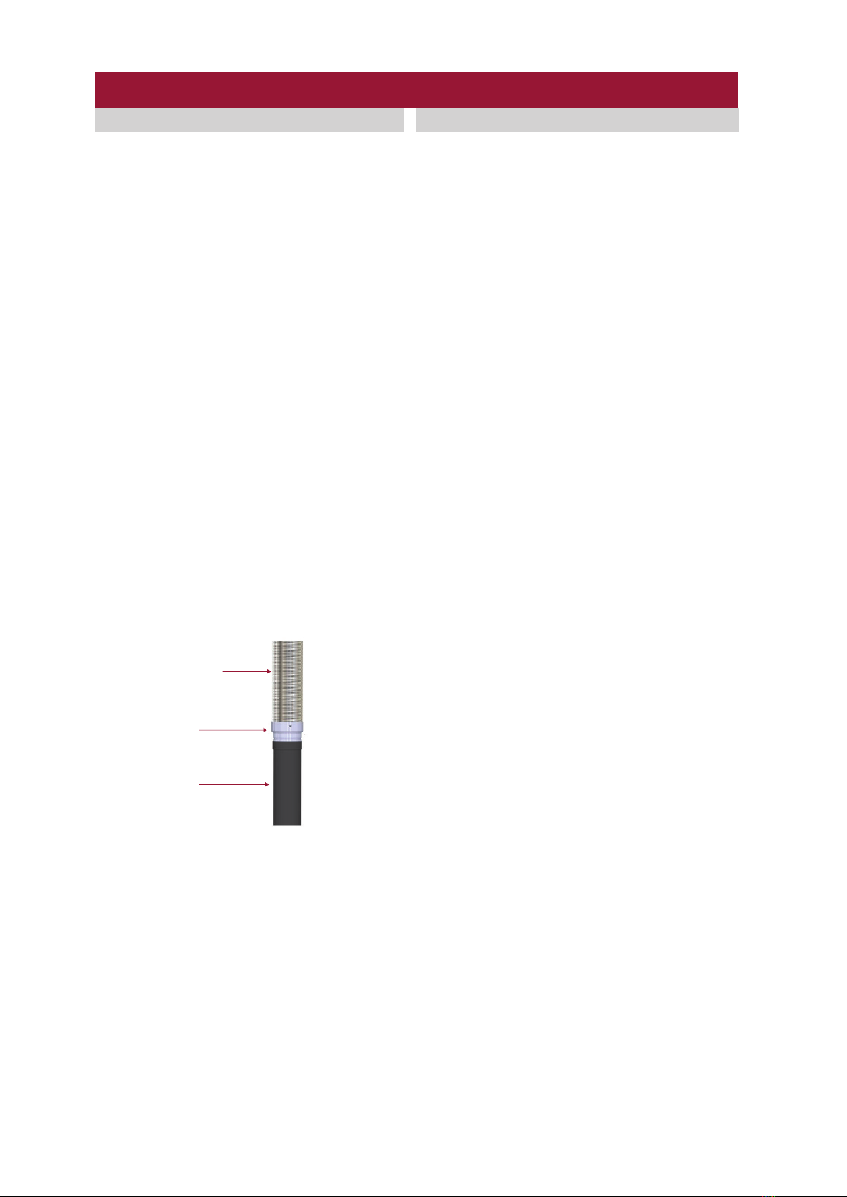
JOINT ASSEMBLY
The male end of the pipe should sit inside the spigot
outlet of the stove and should be sealed with Mi-Flues
high temperature sealant (rated to 1000°C) or fire
cement in accordance with appliance manufacturers
guidelines.
There is a hole in the spigot end of the pipe. This hole
is used in the manufacturing process and is in no way
used for installation purposes.
If the fit is quite loose it is possible to pack the joint with
fire rope prior to using the high temperature sealant
(rated to 1000°C) or suitable fire cement.
Produced in zero carbon steel, it has two coats, both
internally and externally, of superior class A quality
enamel applied.
The system is available in five standard diameters
100mm, 125mm, 150mm, 175mm and 200mm.
Mi-Flues System 7 is available in three standard
colours, Matt Black, Gloss Black and Brown.
System 7 is not suitable for condensing applications.
Locking Clips are available to
suit 100mm, 125mm and
150mm System 7 pipes. They
are recommended on runs of
more than three components.
Mi-Flues do not recommend cutting vitreous enamel
pipes. This is because it is the vitreous enamel
coating that protects the mild steel pipe underneath
from corrosion and attack from combustible deposits.
Once the pipe is cut the mild steel will be exposed.
Adjustable lengths are available to assist in
achieving an exact required length.
Mi-Flues System 7 should not be used on Insert
Stoves. If a connecting flue pipe is required for an
Insert Stove Mi-Flues System 1 or Mi-Flues Insert
Stove kits should be used.
Flue Gas
Direction
To install the locking clip fit the male end of the pipe
into the socket end of the pipe as shown below. Seal
the joint using Mi-Flues high temperature sealant (rated
to 1000°C) or fire cement. Once sealed, fit the locking
clip around the pipe ensuring connection is made with
both pipes. Once in correct position secure the
locking clip by tightening the tensioning screw with a
suitable allen key or flat head screw driver.
Socket (Female)
Male
Mi-Flues System 7 conforms to:
BS 1344 Part 1 Thermal shock resistance
BS 1344 Part 7 Heat resistance
BS EN 14483 Part 1 Acid resistance
BS 6999 Specification for VE low carbon steel flue
pipes
EN 1443:2003 Chimney General Requirements
EN1856-2 T600 N1 D Vm L80180 G(**)
Note: ** 4 x diameter of the flue
3
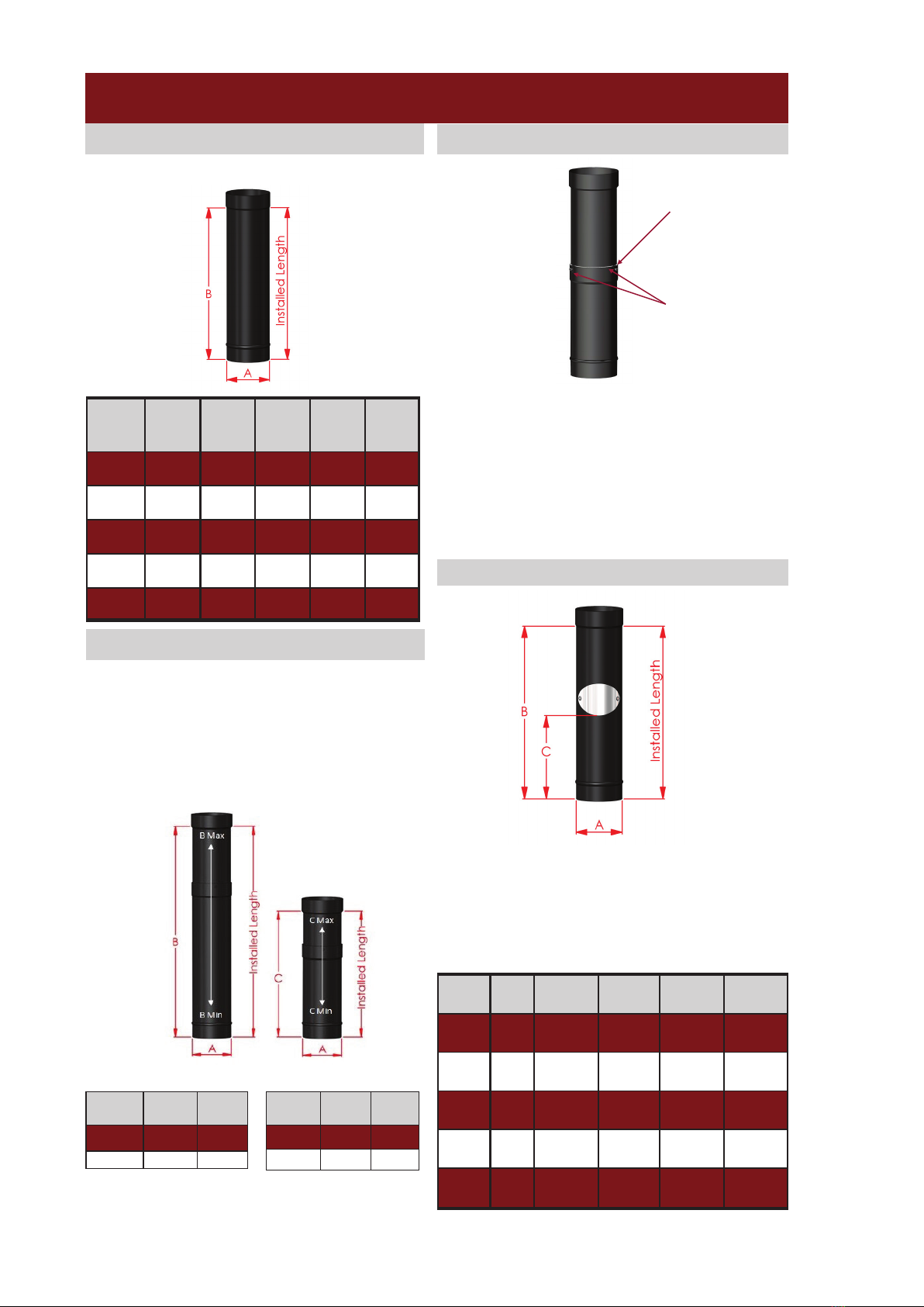
LENGTH -WITH CLEAN OUT DOOR
Provision for inspecting a chimney system must be
made. Lengths with doors are provided for this
purpose. Manufactured with a non corrosive stainless
steel access door with high temperature gasket and
corrosion proof re-usable locking nuts. Lengths are
available in 300mm, 500mm, 1000mm and 1200mm.
LENGTHS
Code Dia. (A)
300
Length
(B)
500
Length
(B)
1000
Length
(B)
1200
Length
(B)
Sys. 7 100 260 460 960 1160
Sys. 7 125 260 460 960 1160
Sys. 7 150 260 460 960 1160
Sys. 7 175 260 460 960 -
Sys. 7 200 260 460 960 -
Code Dia.
(A)
300
Length
500
Length
1000
Length
1200
Length
Sys. 7 100 B=260
C=97
B =460
C =197
B=960
C=447
B=1160
C=547
Sys. 7 125 B=260
C=97
B=460
C=197
B=960
C=447
B=1160
C=547
Sys. 7 150 B=260
C=97
B=460
C=197
B=960
C=447
B=1160
C=547
Sys.7 175 -B=460
C=197
B=960
C=447 -
Sys. 7 200 -B=460
C=197
B=960
C=447 -
Mi-Flues do not recommend cutting vitreous enamel
pipes. Adjustable lengths are available to assist in
achieving the exact length required.
They are available in 125mm and 150mm diameters.
Adjustable lengths are available in a matt black,
gloss black or brown finish. The short component is
adjustable from 310 -480mm. The long component
is adjustable from 510 -880mm.
Available in 300mm, 500mm, 1000mm and 1200mm.
MI-Flues System 7 Vitreous Enamelled Stove Pipe
ADJUSTABLE LENGTHS
Dia (A) 125 150
B Max. 880 880
B Min. 510 510
Long Adjustable Short Adjustable
Dia (A) 125 150
C Max. 480 480
C Min. 310 310
ADJUSTABLE LENGTHS
Telescopic Joint
Locking
Screws
To fit an adjustable length, loosen the locking screws
with a suitable screw driver. Adjust the telescopic
pipes to the required length, ensuring that the overlap
between the two pipes must not be less the 80mm.
Once adjusted to required length, secure the telescopic
lengths by fastening the locking screws. Seal the
telescopic joint using Mi-Flues high temperature
sealant (rated to 1000°) or fire cement.
4
MI-Flues System 7 Vitreous Enamelled Stove Pipe
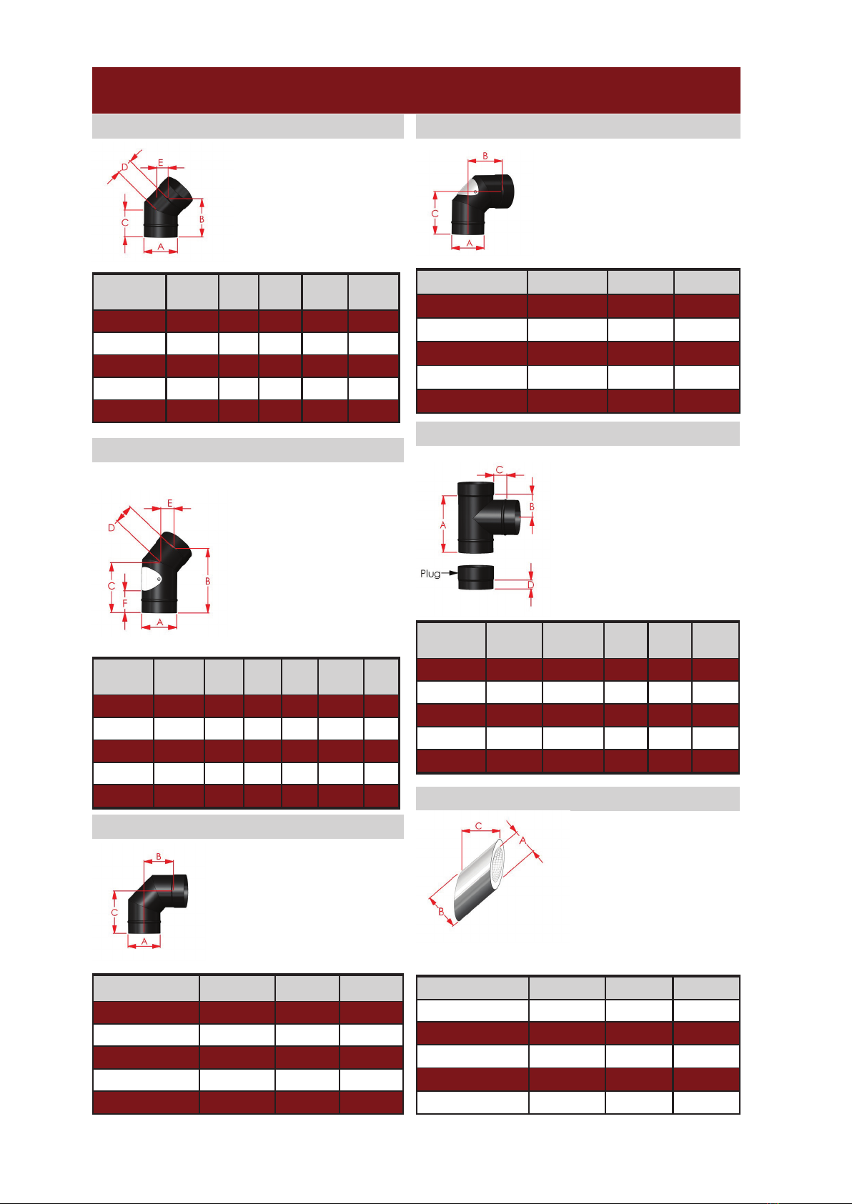
90°TEE -with Cleaning Inspection Cap
A 90°Tee is used at the bottom
of a flue run and allows the flue
system to be easily cleaned. It
is only to be used when
installing the flue at the rear
outlet of a stove. This is also
designed to take a draught
stabiliser.
45° Bend
45° Bend -with clean out door
Product
Code Dia.(A) (B) (C) (D) (E)
Sys. 7 100 145 105 65 45
Sys. 7 125 155 110 70 50
Sys. 7 150 150 110 65 40
Sys. 7 175 170 116 76 54
Sys. 7 200 183 122 87 61
Product
(A) (B) (C) (D) (E) (F)
Sys. 7 100 215 165 65 45 73
Sys. 7 125 215 167 70 50 73
Sys. 7 150 210 160 65 45 73
Sys. 7 175 202 149 76 54 63
Sys. 7 200 215 154 86 61 73
Product
Code Dia. (A) (C)(B) (D)
Sys. 7 100 204 4080 35
Sys. 7 125 251 40108 35
Sys. 7 150 267 40113 35
Sys. 7 175 260 110 40 35
Sys. 7 200 320 140 40 35
90° Bend With Door
Product Dia.(A) (B) (C)
Sys. 7 100 114 154
Sys. 7 125 128 168
Sys. 7 150 132 173
Sys. 7 175 148 188
Sys. 7 200 164 199
Product Dia.(A) (B) (C)
Sys. 7 100 114 154
Sys. 7 125 128 168
Sys. 7 150 132 173
Sys. 7 175 148 188
Sys. 7 200 164 199
90° Bend
45° Insulated Sleeve
Product Dia.(A) (B) (C)
Sys 7 100 150 140
Sys. 7 125 180 140
Sys. 7 150 200 140
Sys 7 175 225 140
Sys 8 200 250 140
Used to provide a 45°
change of direction or can
be used in pairs as an
offset. Two by 45° bends
can be used to create a 90°
bend.
Used to provide a 90°
change of direction. It
may be taken to be
equal to two 45° bends.
Used to provide a 90° change
of direction and includes a
non corrosive stainless steel
access door to facilitate
cleaning of the chimney
system. It may be taken to be
equal to two 45° bends.
Where System 7 passes
through a non combustible
wall, Mi-Flues recommend
that an insulated sleeve is
used around the pipe. An
insulated sleeve is used to
pass the pipe through the
wall thus providing a
continuous uninterrupted
run through it.
This component provides
access for cleaning and
inspection. It is used to
provide a 45° change of
direction. Manufactured
with a non corrosive stain-
less steel access door with
high temperature
gasket and corrosion proof
re-usable locking nuts.
5
MI-Flues System 7 Vitreous Enamelled Stove Pipe
COMPONENTS
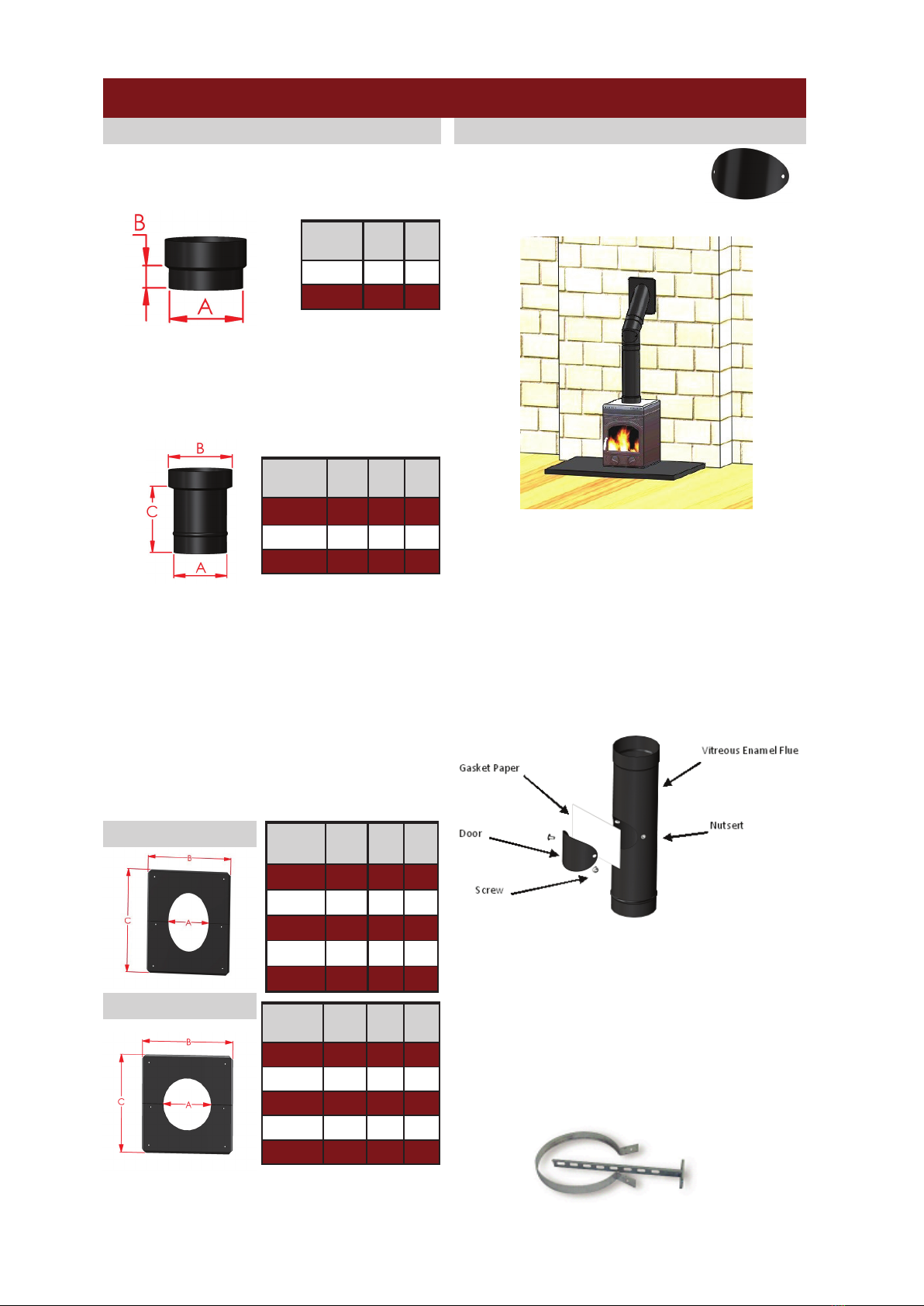
Increasing Adaptor
Designed to enable three diameters of System 7
pipe to be stepped up one diameter as appropriate.
It increases the diameter from 100mm to 125mm,
125mm to 150mm and 150mm to 175mm.
Rosette Plates
A rosette plate is used for aesthetic purposes to
improve the finish of a flue as it penetrates a wall.
Available in diameters from 100 mm to 200mm.
Rosette plates are available in 90° and 45°
angles. They are also available in split form for retro
fitting. Each rosette plate comes individually
packaged. The pack contains one plate, two half
plates in the case of the split rosette, plugs and
screws.
To install, fit the plate/plates around the flue pipe and
secure to a non combustible wall using the fixings
provided.
Adjustable Wall Bracket
A wall bracket provides lateral support to a chimney
run. It is not a load bearing support. Available in
various diameters— Wall bracket length can be
adjusted from 50mm to 250mm by cutting extended
bar.
Brackets are supplied with a stainless steel band and
galvanised stem as shown.
Brackets are not available in a vitreous enamel finish.
They can however be sprayed using a suitable enamel
paint which is available from your local merchant.
Product Dia.
(A) (B) (C)
Sys. 7 100 125 155
Sys. 7 125 150 155
Sys. 7 150 175 155
Product Dia.
(A) (B) (C)
Sys. 7 100 207 207
Sys. 7 125 230 230
Sys. 7 150 254 254
Sys. 7 175 281 281
Sys. 7 200 307 307
45° Rosette Plate
90° Rosette Plate
Coloured finish access door
Start Off Adaptor
This is used to connect an appliance to a System 7
pipe. It is available in 125mm and 150mm.
Product Dia.
(A) (B)
Sys. 7 115 35
Sys. 7 140 35
Product Dia.
(A) (B) (C)
Sys. 7 100 207 250
Sys. 7 125 230 284
Sys. 7 150 254 318
Sys. 7 175 281 356
Sys. 7 200 305 392
To install Mi-Flues System 7 door (as shown below),
firstly remove original door by opening the screws with
a suitable sized Allen key. Ensure surface of pipe is
clean and smooth before fitting new door. To fit the
new door, mate the gasket paper up with the inner face
of the door and pierce two holes to allow for the fitting
of the new screws. While firmly pushing the door
against the pipe in order to maintain a good seal, tight-
en the two screws, fastening the door to the pipe.
Mi-Flues System 7 door comes complete with the
following components: 1x Vitreous enamelled door and
1x Gasket Paper
Mi-Flues can supply a coloured
finished door (on request) as an
alternative to the standard steel finish.
Coloured finish door plus Rosette plate
6
Cleaning / Maintenance
Adequate provision should be made for inspecting and
cleaning the chimney system. Lengths and bends are
available with access doors in the product range. A
90° Tee is also available as an Inspection/Cleaning
component. Cleaning/Inspection access should be
provided to suit the installation, unless sweeping can
be undertaken through the appliance.
The chimney should be inspected regularly and
cleaned at least twice a year, depending on usage and
type of fuel used. This should be carried out with the
use of a brush which should not be made from black
steel.
The chimney should be maintained to ensure that the
construction remains in good condition.
Any components showing signs of deterioration which
may affect performance should be replaced under
professional advice, any evidence of leakage identified
by smoke staining should be rectified immediately.
If removing the access door during the cleaning
process the existing gasket paper should be removed
and replaced.
Replacement gasket paper is available through your
local merchant.
MI-Flues System 7 Vitreous Enamelled Stove Pipe
When a System 7 flue pipe is joined to our System 2
twin wall insulated chimney which penetrates a
combustible ceiling, the upper end of the System 7
pipe should terminate four times the diameter of the
pipe below a combustible ceiling level
Connecting flue pipe components should extend a
distance of 600mm off a solid fuel appliance.
This connection can be sealed using Mi-Flues high
temperature sealant (rated to 1000°C) or a fire
cement and the connection must be made in the
same room as the appliance itself.
Safety / Installation / Regulations
Distance to Combustible materials
Mi-Flues System 7 should be fitted at least four times
the diameter of the pipe away from any
combustible materials.
Chimney Plate
The chimney plate provides information regarding the
Manufacturer, designation, nominal size, distance to
combustibles, Installer name, installation date, chimney
location and thermal distance.
It is to be completed by the Installer and securely fixed
in an unobtrusive but obvious position within the
building such as next to the electricity or gas consumer
unit, next to the chimney hearth or next to the water
supply stop-cock.
Connection to the Chimney
Safety / Installation / Regulations
System 7 must only be used to make the
connection between the appliance outlet spigot and
the chimney. It should not pass through any roof
space, partition wall or floor, except to pass directly
into a chimney through a wall of the chimney (see
installation illustration on final page).
System 7 should be guarded if there could be a risk
of damage or if the burn hazard it presents is not
immediately apparent.
Connection to System 2 twin wall chimney
Connection to Flexible liner through a non
combustible wall
Connection to Mi-Flues System 35 flexible flue liner
can be made either from directly under the chimney
where the appliance is positioned within a fireplace
or through the side of the chimney using one of our
System 35 adaptors suitable for the purpose (see
installation illustration on final page).
Connection to the appliance
System 7 is designed to fit straight into the
appliance outlet spigot without the need for an
adaptor. However, for smaller fitting diameter
spigots, where the joint between the appliance
outlet spigot and the flue pipe is quite loose, an
adaptor is available to improve the tightness of the
joint.
When making the connection between the appliance
outlet and the System 7 pipe Mi-Flues high
temperature sealant (rated to 1000°C) or fire cement
should be applied.
Height of Connecting flue pipe
A run of System 7 Vitreous Enamel pipe should be
limited to no more than a maximum of 1.8 metres.
Bends in Connecting Flue pipes
Top Outlet Appliance—System 7 should have no more
than two bends in its length with an angle no greater
than 45° when measured from the vertical.
Where possible System 7 flue pipe should rise
vertically straight.
Rear Outlet Appliance—Connection to a rear
outlet appliance may be made using the 90° Tee or
bend. The maximum horizontal distance from the
outlet of the spigot should be no more than 150mm on
solid fuel appliances, subject to the appliance
manufacturers installation instructions.
System 7 length
System 35 Adaptor
System 35 flexible flue
7
Life Expectancy
Under normal operating conditions, and providing the
system is installed and maintained correctly,
Mi-Flues System 7 should provide many years
service and is provided with a 10 year conditional life
expectancy. Prolonged periods of slow burning can
however reduce the life expectancy of the product.
Handling and Storage
All System 7 components are individually boxed or
packaged and labelled. Relevant information from the
label should be transferred to the chimney plate.
Product should be stored in a dry suitable storage
location.
The product is easy to handle, but care should be
taken when holding, fitting or assembling any part of
the system.
Users are advised to use suitable precautions such as
gloves, eye/face protection, protective clothing etc to
avoid injury.
Installers should be aware of the Safety, Health and
Welfare at Work Act 2005 & Safety, Health and
Welfare at Work (general application) regulations 2007.
Installers should be aware of the possibility of
disturbing asbestos when working in older properties.
This should be dealt with in accordance with the strict
guidance documents. Particular attention should be
taken to ensure suitable PPE is used when applying
certain fireclays which can be of a caustic nature, as
well as when using any other substances which may
be harmful.
System 7 Technical Data
Fuel Solid Fuel, Oil, Gas
Material
1.8mm Double sided vitreous
enamelled steel
Min. Distance to
combustibles Four times diameter of flue
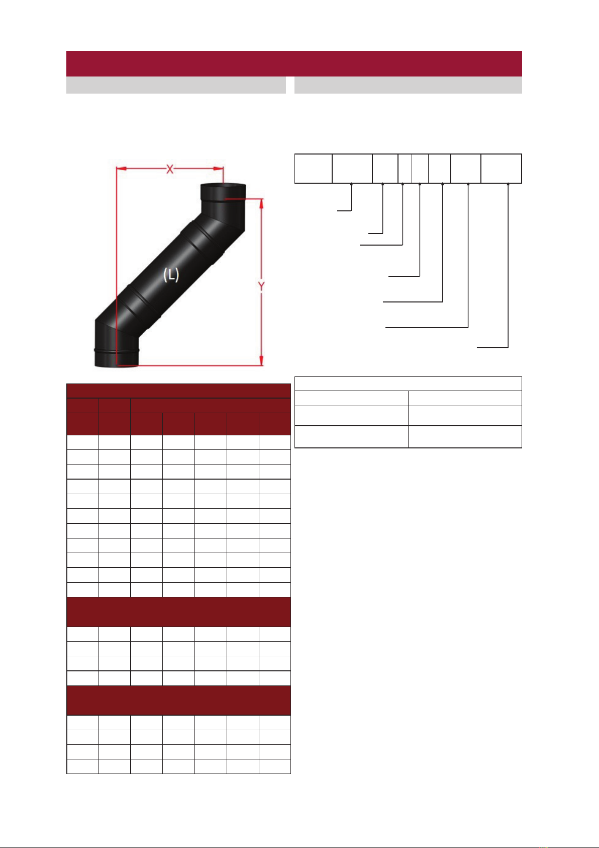
OFFSET CHART
The offset chart below is using the
recommended Mi-Flues System 7 45° bends.
Within a run of system 7 flue no more than two
bends should be used. Two bends are used to
create one offset.
PRODUCT DESIGNATION
Mi-Flues System 7 carries the following product
designation code.
EN1856-2 T600 N1 D Vm L80180 G (**)
Note: **4 x diameter of the flue
System 7 EN1856-2T600 N1 DVm L80180 G(**)
Standard
Temperature Level
Pressure Level
N, P or H
Condensate Resistance
W:Wet or D:Dry
Corrosion Resistance
(durability against corrosion)
Material specification
Sootfire resistance and distance to combustibles
G:Yes or O:No / distance to combustibles in mm
System 7 Offset Chart
Diameter
(L) Offset
100m
m
125m
m
150m
m
175m
m
200m
m
0X118 123 125 137 144
Y284 308 302 337 352
300 X302 311 309 325 331
Y468 492 486 524 540
500 X443 453 450 466 472
Y610 634 628 666 681
1000 X797 801 804 820 826
Y963 987 981 1020 1034
1200 X938 948 945 961 967
Y1105 1129 1123 1161 1176
300mm Adjustable
Length
X Min 309 319 316 332 338
X Max 429 439 437 452 458
Y Min 475 500 494 532 546
Y Max 596 620 614 652 667
500mm Adjustable
Length
X Min 450 460 458 473 480
X Max 712 722 719 735 741
Y Min 617 641 635 673 688
Y Max 878 903 897 935 950
MI-Flues System 7 Vitreous Enamelled Stove Pipe
8
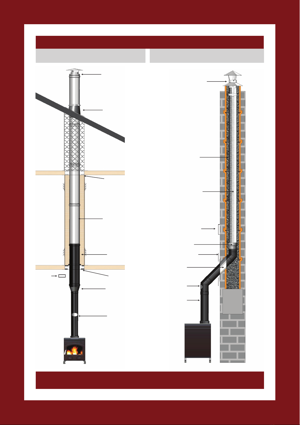
MI-Flues System 7 Vitreous Enamelled Stove Pipe
System 7 Length
with cleaning door
System 2 Twin Wall
Tapered Adaptor
System 2 Firestop
System 2
Length Black
System 2 Length
System 2 Firestop
System 2 Flashing
with Storm Collar
System 2 Cowl
System 7 Length
System 7 Bend
with cleaning door
System 7 Mesh
Insulated Sleeve
System 7 Rosette Plate
System 35 Adaptor
System 35 Flexible Flue
System 35 Pot Hanger Cowl
All flue systems must be installed according to current Building Regulations. Mi-Flues has adopted a policy of continuous product review, and in
the interests of development and improvement the Company reserves the right to vary the appearance and performance of any of its products
without prior notice. Correct at time of print (September 2014). For updates please check our website.
Mi-Flues Ltd , Summerhill Enterprise Ctr., Summerhill, County Meath, IRELAND
Telephone: +353 46 95 58030 Fax: +353 46 95 58034
System 7 connection to an existing brick chimneySystem 7 connection to System 2 twin wall
insulated stainless steel chimney
Back Fill flexible flue
Chimney
Plate
Chimney
Plate
Table of contents
Other Mi-Flues Ventilation Hood manuals


Popular Ventilation Hood manuals by other brands


Electrolux
Electrolux EFT 50466 user manual

Whirlpool
Whirlpool RH7630XL installation instructions

LG
LG DC9201SAU Installation and operating instructions

Electrolux
Electrolux LFG315X user manual

Sirius Range Hoods
Sirius Range Hoods SCH31A installation instructions

ELICA
ELICA Circus Instruction on mounting and use

Franke
Franke FDF 6354 XS Instructions for use and installation

Prizer Hoods
Prizer Hoods CFM300 installation instructions

EF
EF CK-SPECCHIO user manual

NuTone
NuTone RANGEMASTER RM60000 Series Installation instructions and user manual

Miele
Miele DA 6690 W Operating and installation instructions

Franke
Franke FBI 537 XS Instructions for use and installation