Mi-Flues SYSTEM 1 User manual

Tel: +353 46 95 58030
Fax: +353 46 95 58034
Web: www. miflues.ie
SYSTEM 1
Single Wall Connecting
Flue Pipe for Multi-Fuel
Appliances
System1 Single.indd 1 28/06/2013 14:47
September 2014
2
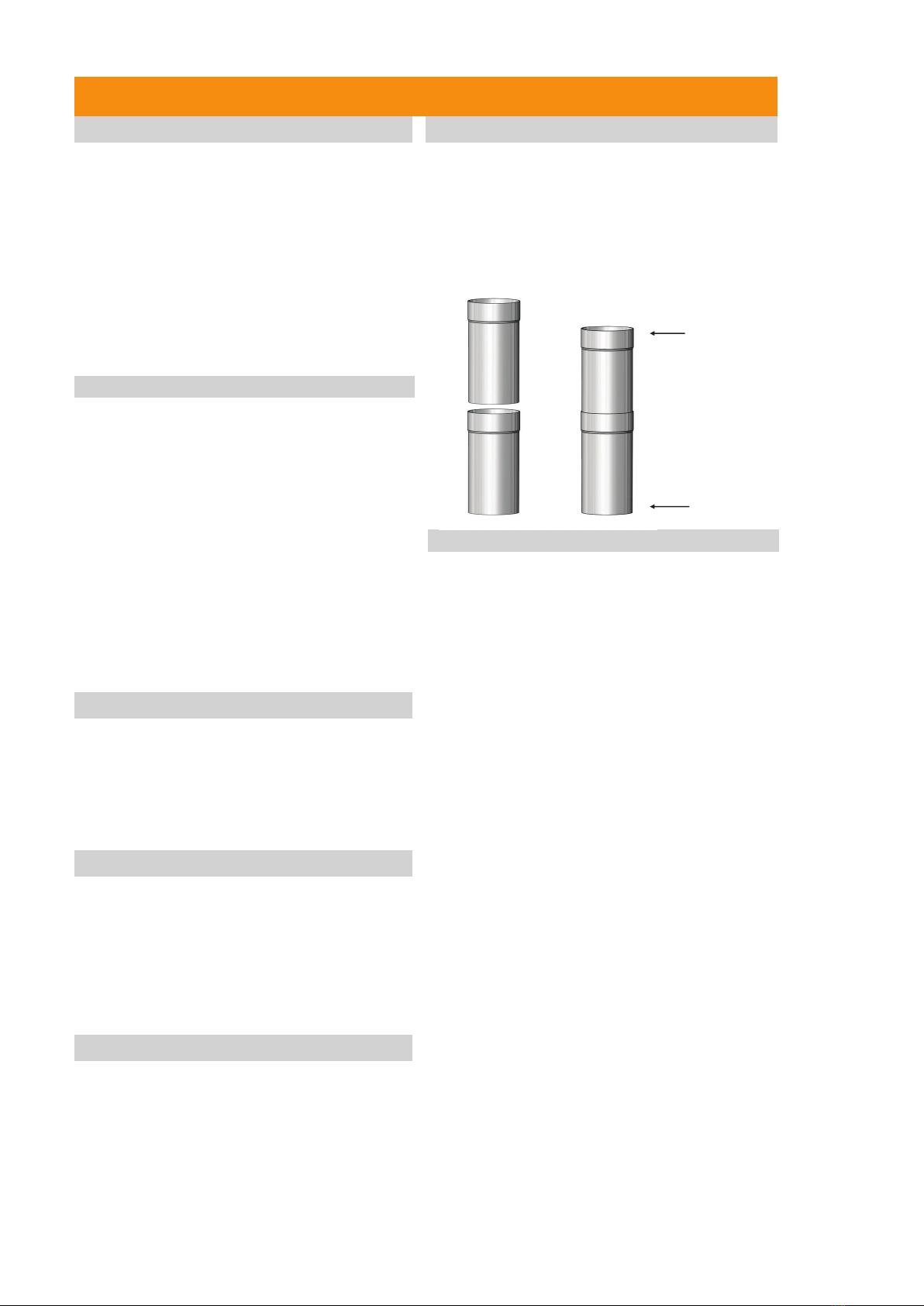
Mi-Flues System 1 allows for a 50mm overlap distance
per joint. All sockets (female end) should be installed
upwards, with the male end dropping into the socket.
To install Mi-Flues system 1 components simply
position the male end into the female socket end and
seal with Mi-Flues high temperature sealant (rated to
1000°C) designed specifically for flues, stoves or fires,
or similar rated fire cement.
PRODUCT DESCRIPTION
JOINTING SYSTEM
Mi-Flues System 1 is a 1mm thick 316 grade
stainless steel single wall connecting flue pipe
suitable for gas, oil, wood and multi-fuel appliances.
It can also be used as a rigid flue liner.
It has been specifically engineered to give an
authentic visual look, whilst at the same time being
manufactured using the latest technology to ensure
years of trouble free use.
The system is available in four standard diameters
125mm, 150mm, 180mm and 200mm.
System 1 is not suitable for condensing applications.
APPLICATION
Mi-Flues System 1 is a single wall connecting flue
pipe suitable for multi-fuel appliances.
It is also suitable for relining existing chimneys.
System 1 pipes are not insulated. Their use as an
external flue is not permitted as they can generate
excessive condensation and disrupt the draw due to
cold outside temperatures.
Mi-Flues System 1 316 grade stainless steel single
wall is suitable for use on applications fired by gas, oil
and solid fuel .
The longitudinal seam on all components is fully
welded to prevent leakage and to ensure a uniform
high quality of manufacture throughout.
Components have been designed to be installed
quickly, safely and simply. Mi-Flues System 1 single
wall flue is designed to be installed with the socket
(female end) directed upwards.
By fitting the flue components together in this manner
ensures debris and moisture will run internally down
the flue.
INTRODUCTION
Mi-Flues System 1 Single Wall Connecting Flue Pipe and Rigid Flue Liner
APPROVALS
COMPONENTS
MI-Flues System 1 components have been designed
to be installed quickly, safely and simply.
The system comprises of plain lengths, adjustable
lengths, bends, bends with inspection/cleaning
access, tees complete with cleaning inspection caps,
cowls and support brackets.
INSTALLATION
Installation in a Masonry Chimney
System 1 is also suitable for relining existing chimneys.
If relining a masonry chimney it should firstly be
cleaned to ensure free passage of the pipe.
The space between the flue and the masonry liner
should be back filled to improve the performance of the
chimney. Mi-Flues System 1 can be connected directly
to the appliance and can also be used to reline a
chimney when installed with the manufacturers
installation instructions. When using as a rigid liner
System 1 should be installed from the bottom up
ensuring that all joints are adequately sealed. The
weight of the System 1 rigid liner should be supported
at the lower end of the chimney with the use of two
rigid members (two metal beams—not supplied by
Mi-Flues) and a half bracket (see page 4 for details).
System 1 has been specifically designed for use as a
connecting flue pipe to facilitate connection from the
outlet of a multi-fuel appliance to the chimney.
Where appropriate it can be used to connect to either
our twin wall System 2 product or in the case of an
existing brick chimney, our System 35 Multi fuel flexible
liner .
In all cases the product must be installed in
accordance with Local Building Regulations Document
J and the manufacturers installation instructions.
The diameter of the pipe used must be equal to or
greater than the outlet of the appliance.
The diameter of pipe used should not be less than the
diameter specified by the appliance manufacturer.
Mi-Flues System 1 is manufactured and conforms to
EN 1856-2 and has the following designation code:
EN 1856-2 T600 N1 D Vm L50100 G(**)
Note: ** 3 x diameter of the flue
Socket-
Female end
Male End
Mi-Flues System 1 should be fitted at least three times
the diameter of the pipe away from any combustible
materials. For example 125mm pipe should be a
minimum of 375mm away from any combustible
material. All sockets (female end) should be upward,
with the male end dropping into the socket .
This ensures that no condensate can escape and spoil
the appearance of the finished installation.
3
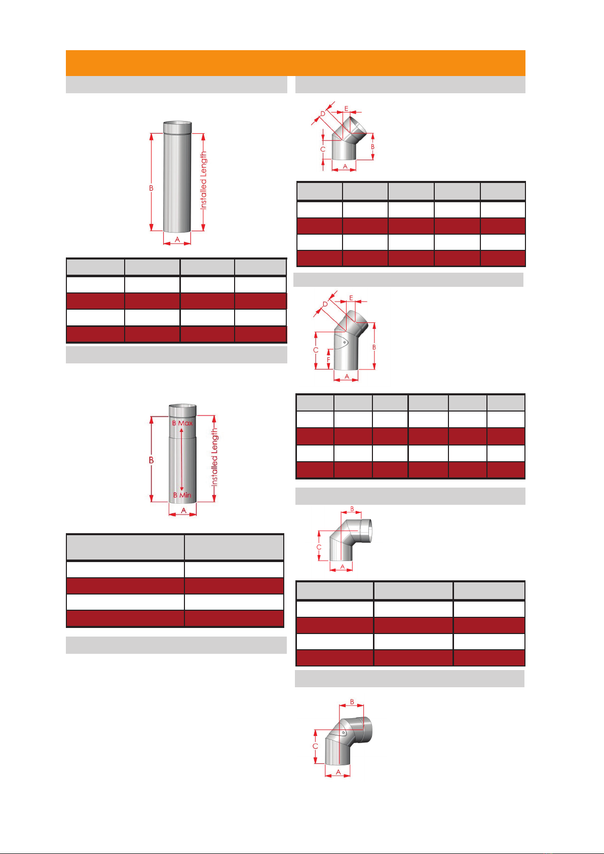
90 ° BEND
LENGTHS 45 ° Bend
Dia(mm) ‘A’ 250(B) 500(B) 1000(B)
125 200 450 950
150 200 450 950
180 200 450 950
200 200 450 950
Dia (A) (B) (C) (D) (E)
125 143 100 55 40
150 155 110 60 42
180 165 118 70 45
200 175 125 70 50
Diameter (A) (B) (C)
125 105 162
150 120 170
180 145 195
200 148 198
ADJUSTABLE LENGTHS
Diameter (mm) (A) ADJ Short
(B) Min—Max
125 255-370
150 255-370
180 255-370
200 255-370
45 ° BEND & DOOR
Dia. (A) (B) (C) (F)(E)(D)
125 200 165 694055
150 200 160 704360
180 235 185 994867
200 250 200 1205070
Lengths are available in 250mm, 500mm and
1000mm.
An adjustable length is used to achieve an exact
required length where a standard length is not
suitable.
Used to provide a 45°
change of direction or can
be used in pairs to create
an offset. Two by 45°
bends can be used to
create a 90° bend.
Used to provide a 90°
change of direction. It
may be taken to be
equal to two 45°
bends.
Mi-Flues System 1 Single Wall Connecting Flue Pipe and Rigid Flue Liner
90 ° BEND & DOOR
ADJUSTABLE LENGTH INSTALLATION
To install an adjustable length, adjust the telescopic
component to the required length, keeping caution
that the overlap between the two pipes must never
be less than 80mm. Seal telescopic joint using
Mi-Flues high temperature sealant (rated to 1000°C)
or fire cement. Once adjusted to the required length,
secure the telescopic length with the use of an
Mi-Flues wall bracket located directly above the
overlap.
This component provides
access for cleaning and
inspection. It is used to provide
a 45° change of direction.
Manufactured with a non
corrosive stainless steel access
door with high temperature
gasket and corrosion proof
re-usable locking nuts.
Used to provide a 90° change
of direction and includes a non
corrosive stainless steel
access door to facilitate
cleaning of the chimney
system. It may be taken to be
equal to two 45° bends. (For
dimensions see above table for
90° bend)
4
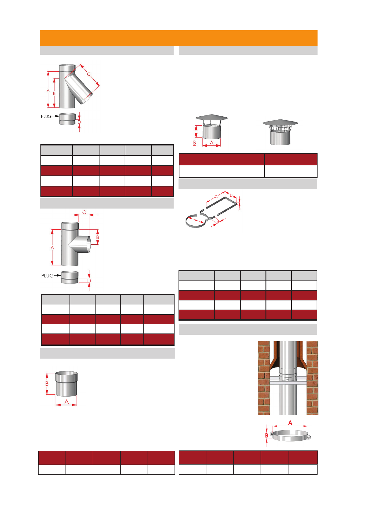
45 ° TEE
90 ° TEE
Diameter (B) (C) (D)(A)
125 235 240 35281
150 270 270 35334
180 298 307 35364
200 335 332 35418
COWL
Dia (A) (B)
125mm, 150mm,180mm,200mm 90
SUPPORT COMPONENT—WALL BRACKET
(A) (B) (C) (D)Diameter
233 93 80 35125
260 106 80 35150
281 116 80 35180
308 130 80 35200
Used to provide lateral
support for the System 1
components. This
component is adjustable
between 60mm—250mm of
a wall face.
START OFF ADAPTOR
Mi-Flues System 1 Single Wall Connecting Flue Pipe and Rigid Flue Liner
Diameter (A) 125 150 180 200
B45 45 45 45
C258 258 258 258
D152 152 152 152
E20 20 20 20
Each bracket comes individually packaged with the
following included:
Wall Section x 1, Joiner Section x 1
Clamping Section x 1, M6x25mm Hex Head Bolt x 2
M6x12mm Hex Head Bolt x 4, M6 Nut x 6
Diameter
(A) 121.5 146.5 176.5 196.5
B130 130 130 130
Mi-Flues System 1 Start Off
Adaptor is used on smaller fitting
diameter spigots, where the
standard size component diameter
will not fit the appliance. This
adaptor is available to ensure
Mi-Flues System 1 pipes can be
fitted. When making the joint
between the appliance outlet and
the System 1 pipe Mi-Flues high
temperature sealant (rated to 1000°
C) or fire cement should be applied.
Tapered reducing adaptors are also
available on request.
A 45° Tee is used to create
a bend in a flue run. It can
be used to change a
chimney run from a
horizontal to a vertical run
when used with a 45° bend.
This component minimises
the resistance to flow
because of the angle
created with the vertical
axis. This component
comes complete with a
removable inspection cap.
A 90° Tee is used to
create a bend in a flue
run. It is used to change
a chimney run from a
horizontal run to a
vertical run.
This component comes
complete with a
Removable inspection
cap . It may also be used
for the fitting of a draught
stabilizer device.
A cowl is the top rain cap for a chimney. Its purpose is
to stop the infiltration of rain or snow to the inside of the
chimney. It does not impede the movement of the
products of combustion. It is pushed down into the last
length of the installation and sealed using Mi-Flues
high temperature sealant (rated to 1000°C).
This cowl is also available with a solid fuel bird guard
protection.
SUPPORT COMPONENT— HALF BRACKET
When using as a rigid liner
System 1 should be
installed from the bottom up
ensuring that all joints are
adequately sealed. The
weight of the System 1 rigid
liner should be supported at
the lower end of the chimney
with the use of two rigid
members (two metal beams—
not supplied by Mi-Flues) and
a half bracket as shown. Each
half bracket comes bubble
wrapped and labelled. Included
are the required two screws and
two nuts for assembling.
Diameter
(A) 125 150 180 200
B20 20 20 20

5
Mi-Flues System 1 should be fitted at least three times
the diameter of the connecting flue pipe away from any
combustible materials.
Excessive runs of single wall connecting flue pipe
should be avoided and limited to no more than a
maximum of 1.8 metres.
Connection to the appliance
Height of Connecting flue pipe
Bends in Connecting Flue pipes
Top Outlet Appliance—The connecting flue pipe
should have no more than two bends in its length
with an angle no greater than 45° when measured
from the vertical.
Where possible the connecting flue pipe should rise
vertically straight.
Rear Outlet Appliance—Connection to a rear
outlet appliance may be made using the 90° Tee
where the removable tee cap will be accessible.
The maximum horizontal distance from the outlet of
the spigot should be no more than 150mm on solid
fuel appliances, subject to the appliance
manufacturers installation
Distance to Combustible Materials
Connection to System 2 twin wall chimney
Connection to Flexible liner within a brick
chimney
Connection to Mi-Flues System 35 flexible flue liner
can be made either from directly under the chimney
where the appliance is positioned within a fireplace
or through the side of the chimney using a System
35 adaptor (see illustration on front cover).
Mi-Flues System 1 Single Wall Connecting Flue Pipe and Rigid Flue Liner
System 1 is designed to fit straight into the
appliance outlet spigot without the need for an
adaptor.
System 1 should only be used to make the
connection between the appliance outlet spigot and
the chimney. It should not pass through any roof
space, partition wall or floor, except to pass directly
into a chimney through a wall of the chimney (see
installation illustration on page 6).
All System 1 joints should be sealed with Mi-Flues
high temperature sealant (rated to 1000°C) or fire
cement should be applied.
Safety / Installation / Regulations
Chimney Plate
On completion of installation a chimney plate should be
completed. The chimney plate provides information
regarding the Manufacturer, designation, nominal size,
distance to combustibles, Installer name, installation
date, chimney location and thermal distance.
It is to be completed by the Installer and securely fixed
in an unobtrusive but obvious position within the
building such as next to the electricity or gas consumer
unit, next to the chimney or hearth or next to the water
supply stop cock.
Cleaning / Maintenance
Adequate provision should be made for inspecting and
cleaning the chimney system. Access components are
available in the product range (bends with doors and
tees) and should be installed to suit the installation,
unless sweeping can be undertaken through the
appliance.
The chimney should be inspected regularly and
cleaned at least twice a year, depending on usage and
type of fuel used. This should be carried out with the
use of a brush which should not be made from black
steel.
The chimney should be maintained to ensure that the
construction remains in good condition.
Any components showing signs of deterioration which
may affect performance should be replaced under
professional advice, any evidence of leakage identified
by smoke staining should be rectified immediately.
Handling and Storage
All System 1 components are labelled. Fitting
instructions appear on the label where applicable.
These labels should be removed from the product prior
to installation and relevant information transferred to
chimney plate. Products should be stored in a dry
suitable storage location.
The product is easy to handle, but care should be
taken when holding, fitting or assembling any part of
the system.
Users are advised to use suitable precautions such as
gloves, eye/face protection, protective clothing etc to
avoid injury.
Installers should be aware of the possibility of
disturbing asbestos when working in older properties.
This should be dealt with in accordance with the strict
guidance documents. Particular attention should be
taken to ensure suitable PPE is used when applying
certain fireclays which can be of a caustic nature, as
well as when using any other substances which may
be harmful.
Life Expectancy
Under normal operating conditions, and providing the
system is installed and maintained correctly,
Mi-Flues System 1 should provide many years
service and is provided with a 10 year life
expectancy.
Structural Considerations
As System 1 does not rely on Locking Bands to
secure the joint, it is critical that the system is
installed between two fixed and secured points
(appliance outlet and chimney inlet).
Where an offset is installed, each bend must be
adequately braced using suitable support
components to restrict any movement of the joint.
Safety / Installation / Regulations
When a System 1 flue pipe is joined to our System 2
twin wall insulated chimney which penetrates a
ceiling, the System 2 chimney should protrude
425mm below the ceiling on a 125mm diameter
chimney and three times the diameter for 150mm,
180mm and 200mm .
Connecting flue pipe components should extend a
distance of 600mm off a solid fuel appliance.
This connection can be sealed using Mi-Flues high
temperature sealant (rated to 1000°C) or a fire
cement and the connection must be made in the
same room as the appliance itself.

6
Mi-Flues System 1 Product Designation
System 1 Technical Data
Fuel—Solid Fuel, Oil and Gas
Material 1mm 316 stainless steel
Min. Distance to
combusbles 3 mes diameter of the ue
Mi-Flues System 1 products carry the following
designation code:
EN 1856-2 T600 N1 D Vm L50100 G (**)
Note: ** 3 x diameter of the flue
System 1 EN1856-2T600 N1 DVm L50100 G(**)
Standard
Temperature Level
Pressure Level
N, P or H
Condensate Resistance
W:Wet or D:Dry
Corrosion Resistance
(durability against
corrosion)
Material specification
Sootfire resistance and distance to
combustibles
G:Yes or O:No / distance to combustibles
in mm
NM (Not Measured) or M (Measured)
OFFSET CHART
This offset chart uses
the recommended
Mi-Flues System 1 45°
bends. Within a run of
system 1 flue no more
than two bends should
be used. Two bends
are used to create one
offset.
System 1 Oset Chart
Diameter
(L) Oset 125mm 150mm 180mm 200mm
0X119 126 135 140
Y285 303 327 338
250 X264 271 280 285
Y430 448 472 483
500 X436 447 457 462
Y607 625 648 660
1000 X794 801 811 815
Y961 978 1002 1013
Adjustable Length
X Min 299 306 316 320
X Max 377 384 393 398
Y Min 466 483 507 518
Y Max 539 556 580 591
Mi-Flues System 1 Single Wall Connecting Flue Pipe and Rigid Flue Liner
System 1 connection to System 2 twin wall
insulated stainless steel chimney
System 1 used as Rigid Flue Liner
System 1 length
System 1 bend with door
System 2 Adaptor
System 2 Insulated sleeve
System 2 Base
Wall Support
System 2 45° Tee
with removable
cap
System 2 length
System 2 bracket
System 2 45° bend
System 2 Cowl
Mi-Flues Ltd , Summerhill Enterprise Centre, Summerhill, County Meath, IRELAND
Telephone: +353 46 95 58030 Fax: +353 46 95 58034
All flue systems must be installed according to current Building
Regulations. Mi-Flues has adopted a policy of continuous product
review, and in the interests of development and improvement the
Company reserves the right to vary the appearance and performance
of any of its products without prior notice. Correct at time of print
(September 2014). For updates please check our website.
Chimney
Plate
System 1 length
System 1 Cowl
System 1 length
System 1 45° bend
Two metal beams (not
supplied by Mi-Flues)
and half bracket used to
support weight of System
1 when used as rigid
liner (see page 4).
System 1 45° bend
Chimney Plate
System 1 length
Table of contents
Other Mi-Flues Ventilation Hood manuals


Popular Ventilation Hood manuals by other brands


Frigidaire
Frigidaire FJWA369TBIS instruction manual

KOBE
KOBE CH2230SQ Installation instructions and operation manual

Electrolux
Electrolux EFC 9411 Operating and installation instructions

Gaggenau
Gaggenau AI 230 700 use and care manual

Hob2Hood
Hob2Hood X79263MV1 user manual

Electrolux
Electrolux EFG50021 user manual