Mi-Flues SYSTEM 39 User manual
Tel: +353 46 95 58030
Fax: +353 46 95 58034
Web: www. miflues.ie
SYSTEM 39
Single Wall 304
Grade Stainless Steel
Connecting and
Relining Flue Pipe
APPLICATION
PRODUCT DESCRIPTION
Mi-Flues System 39 is a factory made single wall flue
system comprising of a range of lengths, tees, bends
and associated fittings and supports.
System 39 is available in five standard diameters:
100mm, 125mm, 150mm, 180mm and 200mm.
All lengths and flue gas carrying fittings are made
from 304-grade stainless steel. This is a high quality
annealed austenitic stainless steel.
The pipe seams are continuously seam welded
which provides an excellent gas sealed joint and
offers minimum resistance to flue gas flow.
System 39 is suitable for the following applications :
Flue gas system for gas and oil fired appliances, as
recommended by the appliance manufacturer
For relining existing chimneys using oil and gas
fired appliances
Ventilation—boiler rooms, laundries and kitchens
Fume extraction
It has been designed for flue gas temperatures not
exceeding 300°C.
It is not suitable for condensing applications.
INTRODUCTION
Mi-Flues System 39 Single Wall Stainless Steel Chimney
APPROVALS
COMPONENTS
Mi-Flues System 39 has been designed to be
installed quickly, safely and simply.
The system comprises of plain lengths, adjustable
lengths, bends, bends with inspection/cleaning
access, tees complete with cleaning inspection caps,
cowls and support brackets.
Mi-Flues System 39 is manufactured and conforms
to :
EN1856-2 T300 N1 D Vm L20040 O(**)
Note : **3 times diameter of the flue
Mi-Flues System 39 is designated suitable for a
connecting flue pipe and rigid chimney liner.
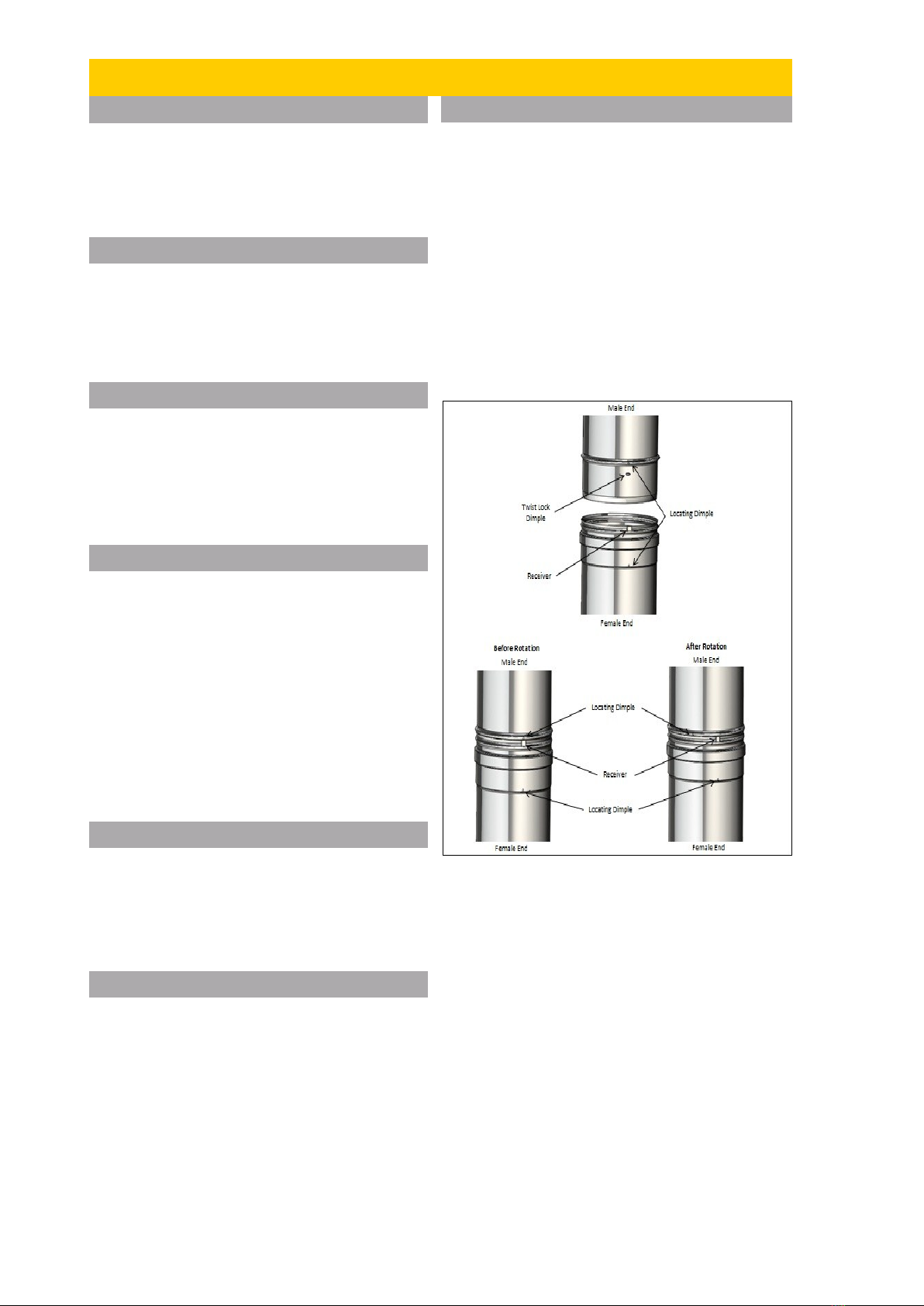
INSTALLATION
1. Select the components required for installation.
2. Ensure the male end of the liner chimney system
always points downwards in the direction of the heating
appliance.
3. Align the locating dimple and twist-lock dimple on
the male end of the chimney liner system with the
locating dimple and receiver on the female end of the
chimney system as shown below.
4.Firmly push both chimney sections together ensuring
to keep locating dimple system in complete alignment .
5. Hold lower chimney section and gently twist
uppermost section to achieve desired twist lock system
Seal using Mi-Flues high temperature sealant (rated
to 1000°C) or a suitable fire cement.
See illustration below
Installation must be in accordance with Building
Regulations Document J.
System 39 operates most efficiently where there is a
vertical run from the appliance to the terminal.
A selection of bends are available to provide an offset
from the vertical. The chimney should not make an
angle more than 45° with the vertical, except where the
flue is connected to the back outlet of the appliance.
To prevent excess condensation of the flue gases and
potential freezing, System 39 is not permitted for
external runs.
Components are joined together by fitting the male
end of the first section into the female end of the
second section (as shown opposite).
Mi-Flues System 39 has a unique press fit jointing
system, which provides structural stability.
This jointing system ensures a quick and easy
installation offering excellent gas tightness
properties.
System 39 has a unique clik clak system which
does not require the use of a locking band.
JOINTING SYSTEM

LENGTHS
Lengths are available in 250mm,
500mm, 1000mm and 1250mm.
(A) Dia (B)250 (B)500 (B)1000 (B)1250
100 196 446 946 1196
125 196 446 946 1196
150 196 446 946 1196
180 196 446 946 -
200 196 446 946 -
Product (A) (B) (C) (D) (E)
Sys.39 100 130 100 50 35
Sys.39 125 138 105 57 42
Sys.39 150 142 109 60 43
Sys.39 180 155 115 67 45
Sys.39 200 162 115 75 54
45° BENDS WITH DOOR
ADJUSTABLE LENGTH
DIA(A) (B) (C) (D) (E) (F)
100 173 135 52 35 35
125 195 163 55 35 69
150 195 165 61 35 70
180 242 185 67 48 99
200 250 200 70 50 120
Product Dia. (A) (B) (C)
Sys.39 100 94 150
Sys.39 125 110 150
Sys.39 150 115 165
Sys.39 180 140 190
Sys.39 200 148 205
90° BENDS WITH DOOR
90° BEND
Product Dia. (A) (B) (C)
Sys.39 100 94 150
Sys.39 125 110 150
Sys.39 150 115 165
Sys.39 180 140 190
Sys.39 200 148 205
45° BEND
Product Diameter (A) ADJ Short (B) Min
-Max
Sys.39 100 340-490
Sys.39 125 340-490
Sys.39 150 340-490
Sys.39 180 340-490
Sys.39 200 340-490
Adjustable lengths are available to
assist achieving the exact length
required where a standard length is
not suitable. Adjust the pipe to the
required length and secure directly
above the overlap joint using a
support bracket. The joint is sealed
using Mi-Flues high temperature
sealant (rated to 1000°C) or a
suitable fire cement. Caution must
be taken that the overlap between
the two pipes must never be less
than 80mm.
Used to provide a 45°
change of direction or can
be used in pairs to create an
offset. Two by 45° bends
can be used to create a 90°
bend.
Used to provide a 45° change of
direction or can be used in pairs
to create an offset. The
inspection door provides access
for cleaning.
Used to provide a 90°
change in direction. It can
be taken to be equal to 2 x
45° bends.
Used to provide a 90°
change in direction. The
inspection door provides
access for cleaning. It can
be taken to be equal to 2 x
45° bends.
Mi-Flues System 39 Single Wall Stainless Steel Chimney

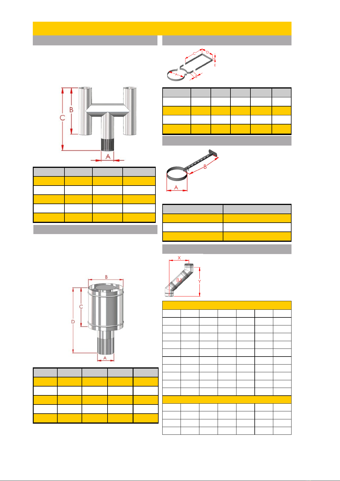
45° TEE
Product (A) (B) (D) (C) Dia.
Sys.39 255 100 25 30 100
Sys.39 255 100 25 30 125
Sys.39 255 100 30 25 150
Sys.39 280 112 30 25 180
Sys.39 305 125 25 30 200
90° TEE
Dia. (A) (B) (C) (D) Product
100 255 206 160 25 Sys.39
125 275 220 200 25 Sys.39
150 336 270 220 25 Sys.39
180 366 298 257 25 Sys.39
200 420 335 290 25 Sys.39
CHIMNEY TERMINATION—COWLS
Used to provide a 45° change
of direction. Also used as an
inspection/cleaning
component.
Used to provide a 90° change
of direction. Also used as an
inspection/cleaning
component.
A cowl is the top rain cap for a chimney. Its purpose is
to stop the infiltration of rain or snow to the inside of the
chimney. For oil fired appliances a stainless steel cowl
is attached to the end of the flue pipe (cowls with bird
guards are not available for oil appliances). For gas
appliances a cowl with mesh should be used.
ADAPTORS—START OFF
Product (A) (B)
Sys.39 100 85
Sys.39 125 85
Sys.39 150 85
Sys.39 180 85
Sys.39 200 85
ADAPTOR—REDUCING (Tapered)
Mi-Flues System 39 Single Wall Stainless Steel Chimney
STORM COWL
The Storm Cowl offers the
greatest protection against rain
and adverse weather
conditions. It reduces the
possibility of wind affecting the
appliance. It can be used on oil
fired appliances. It should be
secured in position with the use
of stainless steel self
tappers or rivets (not provided
by Mi-Flues)
Product (A) (B) (C)
Sys.39 100 272 155
Sys.39 125 295 155
Sys.39 150 320 155
Sys.39 180 347 155
Sys.39 200 370 155
Dia. (A) (B)
100 76
125 76
150 76
180 76
200 76
Product (A) (B) (C)
Sys.39 100 80 130
Sys.39 125 100 130
Sys.39 150 125 130
Sys.39 180 150 130
Sys.39 200 180 130
The System 39 start off adaptor
can only be used on oil and gas
appliances where recommended
by the appliance manufacturer.
(The table below gives the
nominal diameter prior to
crimping).
The System 39 reducing adaptor
can only be used on oil and gas
appliances where recommended by
the appliance manufacturer.
Product (A) (B) (C) (D) (E)
Sys.39 125 45 258 152 20
Sys.39 150 45 258 152 20
Sys.39 180 45 258 152 20
Sys.39 200 45 258 152 20
WALL BRACKET
Mi-Flues System 39 Single Wall Stainless Steel Chimney
A Wall Bracket provides
lateral support. It should
be used at 1.5mtr intervals.
This component is
adjustable between 60mm
and 250mm off a wall face.
H COWL
A H Cowl is used to reduce the possibility of down
draught problems occurring. The H Cowl slides
telescopically inside the previous length. It can be
used on oil fired appliances. It can be secured in
position with the use of stainless steel self tappers or
rivets (not provided by Mi-Flues)
ANTI DOWNDRAUGHT COWL
An Anti Downdraught cowl is used to reduce the
possibility of a down draught problem. It slides
telescopically inside the previous length. It can be
secured in position with the use of stainless steel
self tappers or rivets (not provided by Mi-Flues)
(A) (B) (C) (D) Product
100 205 250 529 Sys.39
125 230 250 545 Sys.39
150 276 305 564 Sys.39
180 322 356 764 Sys.39
200 369 405 919 Sys.39
ECONOMY WALL BRACKET
Product (A) (B) (C)
Sys.39 100 350 592
Sys.39 125 457 751
Sys.39 150 457 751
Sys.39 180 490 795
Sys.39 200 560 900
Dia. (A) (B)
100 250
125 250
150 250
The Economy Wall Bracket
provides lateral support. The
T piece is fixed to the wall
with fittings adequate for the
purpose. The wrap around
section is clamped around
the flue section and fastened
to the T Piece with the nut
and bolt supplied.
This offset chart uses the
recommended Mi-Flues System
39 45° bends. Within a run of
system 39 flue no more than two
offsets should be used. Two
bends are used to create one
offset.
(L) 100mm 125mm 150mm 180mm 200mm
0 X
Y
250 X
Y
500 X
Y
1000 X
Y
1250 X
Y
OFFSET CHART

Distance to Combustible materials
Mi-Flues System 39 should be fitted at least three
times the diameter of the pipe away from any
combustible materials.
Cleaning / Maintenance
Adequate provision should be made for inspecting
and cleaning the chimney system. Lengths and
bends are available with access doors in the product
range. A 90° Tee is also available as an Inspection/
Cleaning component. Cleaning/Inspection access
should be provided to suit the installation, unless
sweeping can be undertaken through the appliance.
The chimney should be inspected regularly and
cleaned at least twice a year, depending on usage
and type of fuel used. This should be carried out with
the use of a brush which should not be made from
black steel.
The chimney should be maintained to ensure that the
construction remains in good condition.
Any components showing signs of deterioration
which may affect performance should be replaced
under professional advice, any evidence of leakage
identified by smoke staining should be rectified
immediately.
Please ensure that labels are removed from
product prior to installation and relevant
information transferred to chimney plate.
SAFETY /INSTALLATION/REGULATION
Handling and Storage
All System 39 components are individually labelled.
They should be stored in a dry suitable storage
location. The product is easy to handle, but care
should be taken when holding, fitting or assembling
any part of the system.
Users are advised to use suitable precautions such
as gloves etc to avoid injury.
Life Expectancy
Under normal operating conditions, and providing the
system is installed and maintained correctly,
Mi-Flues System 39 should provide many years
service and is provided with a 10 year conditional life
expectancy.
Mi-Flues System 39 Single Wall Stainless Steel Chimney
Mi-Flues Ltd , Summerhill Enterprise Centre., Summerhill, County Meath, IRELAND
Telephone: +353 46 95 58030 Fax: +353 46 95 58034
Email: sales@miflues.ie Website www.miflues.ie
All flue systems must be installed according to current Building Regulations. Mi-Flues has adopted a policy of continuous product review, and in the interests of
development and improvement the Company reserves the right to vary the appearance and performance of any of its products without prior notice. Correct at time of
print. For updates please check our website.
System 39 EN1856-2 T300 N1 D Vm L20040 O(**)
System 39 EN1856-2 T300 N1 D Vm L20040 O
Standard
Temperature Level
Pressure Level
N, P or H
Condensate Resistance
W:Wet or D:Dry
Corrosion Resistance
(durability against
corrosion)
Material specification
Sootfire resistance and distance to combustibles
G:Yes or O:No / distance to combustibles in mm
NM (Not Measured) or M (Measured)
PRODUCT DESIGNATION
Technical Data
SYSTEM 39 CONNECTION TO EXISTING CHIMNEY
Note: **3xdiameter of the flue
System 39 length
System 39 bend
with cleaning door
System 39 lengths or
System 4 flexible flue
Chimney Plate
The chimney plate provides information regarding
the Manufacturer, designation, nominal size,
distance to combustibles, Installer name, installation
date, chimney location and thermal distance.
It is to be completed by the Installer and securely
fixed in an unobtrusive but obvious position within
the building such as next to the electricity or gas
consumer unit, next to the chimney or hearth or next
to the water supply stop cock.
Chimney Plate
Table of contents
Other Mi-Flues Ventilation Hood manuals


Popular Ventilation Hood manuals by other brands


Dacor
Dacor DH3006 Use & care manual

Baumatic
Baumatic BTC6740SS instruction manual

Zephyr
Zephyr Twister AK8000AS Use, care and installation guide

Omega
Omega OA2416W Installation and operating instructions

Monogram
Monogram ZV830 installation instructions

Miele
Miele DAS 4940 Operating and installation instructions