Michigan Pneumatic Tool 750SS Series User manual

Industrial Air Tools
750SS
3/4" Impact
751SS 1" Model also available
754SS #4 Spline Model also available
1-800-521-8104 •www.michiganpneumatic.com
Manual

2
Table of Contents
Features
Table of Contents � � � � � � � � � � � � � � � � � � � � � � � � � � � � � � � � 2
Features � � � � � � � � � � � � � � � � � � � � � � � � � � � � � � � � � � � � � 2
Safety � � � � � � � � � � � � � � � � � � � � � � � � � � � � � � � � � � � � � � 3
Maintenance � � � � � � � � � � � � � � � � � � � � � � � � � � � � � � � � � � � 10
750SS Specications � � � � � � � � � � � � � � � � � � � � � � � � � � � � � � 11
751SS Specications � � � � � � � � � � � � � � � � � � � � � � � � � � � � � � 12
754SS Specications � � � � � � � � � � � � � � � � � � � � � � � � � � � � � � 13
750SS, 751SS, 754SS Parts � � � � � � � � � � � � � � � � � � � � � � � � � � � 14
Disassembly � � � � � � � � � � � � � � � � � � � � � � � � � � � � � � � � � � � 16
Assembly� � � � � � � � � � � � � � � � � � � � � � � � � � � � � � � � � � � � � 20
Troubleshooting � � � � � � � � � � � � � � � � � � � � � � � � � � � � � � � � � 25
Limited Warranty � � � � � � � � � � � � � � � � � � � � � � � � � � � � � � � � 26
Notes � � � � � � � � � � � � � � � � � � � � � � � � � � � � � � � � � � � � � � � 27
All the Power of a 1" Impact in the Compact Size of a Traditional
3/4" Class Pistol Grip Tool.
2000 ft-lbs Reverse Torque.
1800 ft-lbs Forward Torque.
Low Air Consumption at 58 cfm.
Weighs Only 13.5 lbs.
300 Series Stainless Steel Hammer Case Housing and Throttle
Components.
3 Options for Anvil: 3/4" Dual Retainer Anvil, 1" Dual Retainer Anvil,
#4 Spline Anvil.
The 750SS Series Impact offers the highest power to weight ratio in a 3/4"
impact. Featuring Stainless Steel Hammer Case and Throttle Components for
use in corrosive environments. The inevitable water and debris that is found in
compressed air systems is no match for the stainless steel throttle parts and
motor design. The combination of the bronze end plates and stainless steel
cylinder prevent the 750SS series tools from becoming seized after sitting for
a nominal period of time with condensation in the motor chamber. The Dual
Retainer design on the 3/4" Sq. and 1" Sq. Drive anvils provide the operator with
socket retainer options. The Twin Hammer design in conjunction with tight motor
tolerances delivers extreme torque. Made in the USA.
1
2
3
4
5
6
7

3
General Product Safety
Information
• Failure to observe the following
warnings and failure to avoid
these potentially hazardous
situations could result in death or
serious injury.
• Read and understand this
and all other supplied manuals
before installing, operating
repairing, maintaining, changing
accessories or working near
this product.
• Only qualied and trained
operators should install, adjust
or use the tool.
• It is your responsibility to
make this safety information
available to others that will
operate this product.
• The warnings given in this and
all other supplied manuals are for
identifying hazards that are fore-
seeable in the general use of
this tool. However, specic
applications may create other
hazards that must be identied
and reduced before using the tool.
• Always install, operate, inspect
and maintain this product in
accordance with all applicable
standards and regulations (local,
state, country, federal, etc.)
Operate and maintain this tool
as recommended in this manual
to prevent an unnecessary
increase in noise, vibration, dust
and fume hazards.
WARNING
Product Safety
Information – When
Placing the Tool in
Service
• Before beginning a job the
operator or their employer must
assess all potential risks of
using this product to do the job.
These risks must be eliminated
or appropriate controls must be
implemented to reduce the risk
to a safe level.
• Always use clean, dry air at 90
psig (6.2 bar/620 kPa) maximum
air pressure at the inlet, unless a
higher pressure rating is specied
on the tool. Exceeding the
maximum rated pressure (PMAX)
shown on the tool may result in
hazardous situations including
excessive speed, rupture, or
incorrect output torque or force.
• Ensure an accessible
emergency shut off valve has
been installed in the air supply
line, and make others aware of
its location.
• Install a properly sized Safety
Air Fuse upstream of hose and
use an anti-whip device across
any hose coupling without
Safety

4
internal shut-off to prevent
hose whipping if a hose fails or
coupling disconnects.
• Whenever universal twist
couplings (claw couplings)
are used, lock pins should be
installed to prevent connection
failure. Whip hoses can cause
severe injury. Do not use
damaged, frayed or deteriorated
air hoses and ttings. Check
that all ttings are tight before
applying air pressure.
WARNING
Product Safety
Information – General
Hazards While Tool
In Use
• Always use Personal Protective
Equipment appropriate to the
tool used and material worked.
This may include dust masks
or other breathing apparatus,
safety glasses, ear plugs, gloves,
apron, safety shoes, hard hat
and other equipment.
• Air under pressure can cause
severe injury. Never direct air at
yourself or anyone else.
• Always turn off the air supply.
Bleed the air pressure and
disconnect the air supply
hose when not in use before
performing any maintenance on
this tool or any accessory.
• Keep clear of whipping air
hoses. Shut off the compressed
air before approaching a
whipping hose.
• Do not use power tools when
tired or under the inuence of
medication, drugs or alcohol.
• Never use a damaged or
malfunctioning tool or accessory.
• Do not modify the tool,
safety devices or accessories.
Modications can reduce the
effectiveness of safety measures;
increase the risks to the operator,
and void the warranty.
• Do not use this tool for
purposes other than
recommended.
• Exposed throttles shall not
be used where obstructions
can hold the throttle in the
“on” position.
• When a secondary handle
is supplied ensure it is properly
installed and use two hands to
maintain control when operating
the tool.
• Impact Wrenches are not
torque wrenches. Connections
Safety

5
requiring specic torque must be
checked with a torque meter after
tting with an impact wrench.
Workplace Hazards
• Slips, trips and falls are major
causes of workplace injury. Keep
work area clean, uncluttered,
ventilated, and illuminated.
• Be aware of slippery surfaces
caused by the use of the tool and
also of trip hazards caused by
the air line.
• For overhead work, safety
helmets must be worn. The
increased risks to the operator
and others must be assessed
and reduced to a safe level.
• Keep others at a safe distance
from your work area or ensure
they use appropriate Personal
Protective Equipment.
• This tool is not designed for
use in potentially explosive
atmospheres including those
caused by fumes, dust or near
ammable materials.
• This tool is not insulated
against electric shock.
Be aware of buried, hidden
or other hazards in your work
environment. Do not contact
damage cords, conduits, pipes or
hoses that may contain electrical
wires, explosive gases or
harmful liquids.
Projectile Hazards
• Always wear eye protection
when operating or performing
maintenance on this tool. The
grade of protection required
should be assessed for each use
and may include impact-resistant
glasses with side shields,
goggles, or a full face shield over
those glasses.
• Ensure work pieces are secure.
Use clamps or vises to hold work
piece whenever possible.
• Failure of the work piece,
socket, tool drive end, extension
or accessories can generate
high-velocity projectiles.
Noise Hazards
• Always wear hearing protection
when operating this tool.
• Exposure to high noise levels
can cause permanent, disabling
hearing loss and other problems
such as tinnitus (ringing, buzzing,
whistling or humming in the
ears). Therefore, risk assessment
and the implementation of
appropriate controls for these
hazards are essential.
Safety

6
• Appropriate controls to reduce
the risk from noise hazards may
include actions such as damping
materials to prevent work pieces
from “ringing.”
• If the tool has a silencer, always
ensure it is in place and in good
working order when the tool is
being operated.
Operating Hazards
• Operators and maintenance
personnel must be physically
able to handle the bulk, weight
and power of the tool.
• Keep body stance balanced
and rm. Do not overreach when
operating this tool. Anticipate
and be alert for sudden changes
in motion, reaction torques
or forces during start up and
operation. The operator should
change posture during extended
tasks, which can help avoid
discomfort and fatigue.
• Use of the tool can expose
the operator’s hands to hazards,
including crushing, impacts,
cuts, abrasions and heat. Wear
suitable gloves to protect hands.
However, ensure that the gloves
do not restrict your ability to
release the trigger or throttle
mechanism.
• To avoid accidental starting –
ensure the tool is in the “off”
position before applying air
pressure, avoid the throttle when
carrying, and release the throttle
with loss of air.
• Do not lubricate tool with
ammable or volatile liquids
such as kerosene, diesel or jet
fuel. Use only recommended
lubricants.
• Do not carry or drag the tool by
the hose.
• Tool and/or accessories may
briey continue their motion after
throttle is released.
• On Reversible tools, note
the position of the reversing
mechanism before operating
the tool so as to be aware of
the direction of rotation when
operating the throttle.
Accessory Hazards
• Use only sizes and types of
accessories and consumables
that are recommended by
the tool manufacturer; do not
use other types or sizes of
accessories or consumables.
• Periodically check the drive
end of the tool to make certain
that the socket retainer functions
correctly and that socket and
Safety

7
drive ends are not excessively
worn which may allow the socket
to come off during rotation.
• Use only impact sockets and
accessories in good condition, as
poor condition or hand (chrome)
sockets or accessories can
shatter and become a projectile
when used with power tools.
Dust and Fume Hazards
• Wear appropriate respiratory
protection if dust or fumes are
present in the work area.
• Dust and fumes generated
when using power tools, and
existing dust disturbed by their
use can cause ill health (for
example, cancer, birth defects,
asthma and/or dermatitis,). Risk
assessment and implementation
of appropriate controls for these
hazards are essential. The priority
shall be to control them at the
source.
• Direct the exhaust so as to
minimize disturbance of dust in a
dust-lled environment.
• All integral features or
accessories for the collection,
extraction or suppression of
airborne dust or fumes should be
correctly used and maintained
in accordance with the
manufacturer’s instructions.
Prevent exposure and inhalation
of harmful dust and particles
created by power tool use.
• Some dust created by power
sanding, sawing, grinding, drilling
and other construction activities
contain chemicals known to
cause cancer, birth defects, or
other reproductive harm. Some
examples of these chemicals are:
• Lead from lead based paints
• Crystalline silica from bricks
and cement and other
masonry products
• Arsenic and chromium from
chemically treated lumber
• Your risk from these exposures
varies, depending on how often
you do this type of work.
• To reduce your exposure to
these chemicals: work in a well
ventilated area and work with
approved safety equipment
such as dust masks that are
specially designed to lter out
microscopic particles.
Entanglement Hazards
• Entanglement of loose clothing,
personal jewelry, neckwear, hair,
gloves or other items can occur if
not kept away from the working
end of the tool. Entanglement
can result in choking, scalping,
lacerations, broken bones and/or
severed extremities.
Safety

8
• Never hold the rotating drive,
drive extension, socket or other
accessory, especially when
wearing gloves.
Vibration Hazards
• Power tools can vibrate in
use. Exposure to vibration can
cause disabling damage to
the nerves and blood supply
of the hands and arms. If you
experience numbness, tingling,
pain or whitening of the skin in
your ngers or hands, stop using
the tool and seek advice from
a qualied health professional
before resuming use.
• Hold the tool with a light but
safe grip, taking account of the
required hand reaction forces
because the risk arising from
vibration is generally greater
where the grip force is higher.
• Wear warm clothing when
working in cold conditions and
keep your hands warm and dry.
• Do not use worn or ill-tting
sockets or extensions, as this
is likely to cause a substantial
increase in vibration.
• Do not touch sockets or
accessories during impacting,
as this increases the risk of cuts,
burns or vibration injuries.
Repetitive Motion
Hazards
• Repetitive motions or
uncomfortable positions may
be harmful to your hands, arms,
shoulders, neck or other parts
of the body. Stop using any tool
if symptoms such as persistent
or recurring discomfort, pain
throbbing, aching, tingling,
numbness, burning sensations
or stiffness occur. These warning
signs should not be ignored.
Seek advice from a qualied
health professional before
resuming use.
WARNING
Product Safety
information – When
Maintaining the Tool
• Keep the tool operating safely
through regular preventative
maintenance including regular
checks of speed and vibration.
• When maintaining the tool,
avoid exposure or breathing
of hazardous dust and other
substances deposited on the tool
during use.
• Use only proper cleaning
solvents to clean parts. Use
only cleaning solvents which
meet current safety and health
Safety

9
standards. Use cleaning solvents
in a well ventilated area.
• Do not remove any labels.
• Replace any damaged label.
NOTICE: Refer to Product
Information Manual for Model
Specic Safety Information.
Wear Respiratory
Protection
Wear Eye
Protection
Wear Hearing
Protection
Read Manuals
Before Operating
Product
Safety
10
Lubrication
1. Each time a tool is dis-
assembled for maintenance
or repair, the tool must be
lubricated.
2. Work approximately 15 cc
of Mobil Mobilux EP2 Lithium
Grease into the Impact
Mechanism.
3. Generously coat the Anvil,
Hammers and Hammer Case
Bushing with grease while
assembling.
4. Coat the vanes with Marvel Air
Tool Oil before sliding them into
the rotor.
5. For routine maintenance, inject
4-5 cc of grease into the grease
tting (750SS-15) using a low
pressure grease gun after every
40 hours of run time.
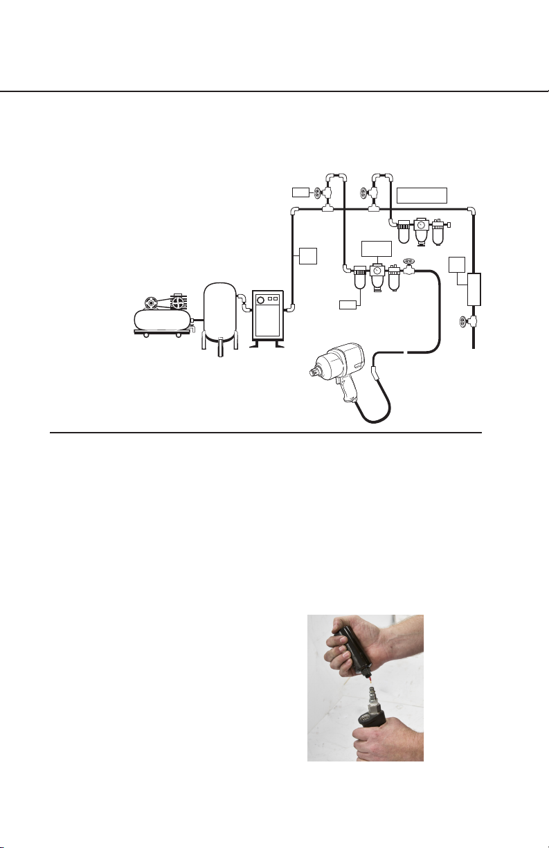
6. Apply 6-8 drops of Marvel Air
Tool Oil into the inlet prior to and
after each use (see gure 10.2).
Air Supply
1. Always use clean, dry air
at 90 psig (6.2 bar/620kPa)
maximum air pressure.
2. Be sure all hoses and ttings
are the correct size and are
secured tightly.
3. Always use a Filter, Regulator,
Lubricator (see gure 10.1).
Maintenance
Compressor
Air Tank
Air
Dryer
Main
Pipe
Valve Higher than
1/100 inclination
Pressure
Regulator
Drain
Tank
Filter
Bigger Hose Better
Figure 10.1
Figure 10.2

11
Michigan
PneuMatic tool, inc.
Model
MP-750SS
3/4" Impact Wrench
Offers one of the industry’s highest power-to-weight ratios. Featuring a
stainless steel hammer case and a twin hammer design for increased durability.
Constructed with non-corrosive materials for prolonged eld life. 100% Made
in the USA.
Anvil ........................ 3/4" Sq. Dual Retainer
Max Torque (Forward) ................... 1800 ft-lbs
Max Torque (Reverse).................... 2000 ft-lbs
Free Speed ............................. 4600 rpm
Length ....................................... 9"
Weight...................................13.5 lbs
Air Inlet Thread ............................... 3/8"
Rec’d Hose Size .............................. 1/2"
Avg. Air Consumption .......................58 cfm
01272017Rev9PFT | MF
Specication Sheet

12
Michigan
PneuMatic tool, inc.
01272017Rev7PFT | MF
Anvil ......................... 1" Sq. Dual Retainer
Max Torque (Forward) ................... 1800 ft-lbs
Max Torque (Reverse).................... 2000 ft-lbs
Free Speed ............................. 4600 rpm
Length ....................................... 9"
Weight................................... 13.5 lbs
Air Inlet Thread ............................... 3/8"
Rec’d Hose Size .............................. 1/2"
Avg. Air Consumption .......................58 cfm
Model
MP-751SS
1" Impact Wrench
Offers one of the industry’s highest power-to-weight ratios. Featuring a
stainless steel hammer case and a twin hammer design for increased durability.
Constructed with non-corrosive materials for prolonged eld life. 100% Made
in the USA.
Specication Sheet

13
Michigan
PneuMatic tool, inc.
Anvil ..............................#4 Spline Drive
Max Torque (Forward) ................... 1800 ft-lbs
Max Torque (Reverse).................... 2000 ft-lbs
Free Speed ............................. 4600 rpm
Length ....................................... 9"
Weight................................... 13.5 lbs
Air Inlet Thread ............................... 3/8"
Rec’d Hose Size .............................. 1/2"
Avg. Air Consumption .......................58 cfm
Offers one of the industry’s highest power-to-weight ratios. Featuring a
stainless steel hammer case and a forged hammer frame for increased durability.
Constructed with non-corrosive materials for prolonged eld life. 100% Made
in the USA.
Model
MP-754SS
#4 Spline Drive Impact Wrench
01272017Rev5PFT | MF
Specication Sheet
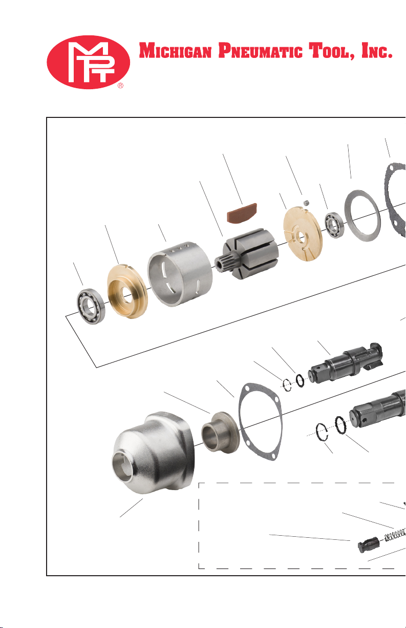
14
MP-750SS 3/4" Pistol Impact
MP-751SS 1" Pistol Impact
MP-754SS #4 Spline Drive Impact
750SS-01
Motor Housing
750SS-02
Throttle Valve Seat
750SS-08
Inlet Bushing O-Ring
750SS-09
Mufer
750SS-36
Hammer Case Bushing
750SS-34
Hammer Case Gasket
750SS-33
Hammer Pin (2)
750SS-31
Hammer Frame
750SS-30
Hammer Frame Washer
750SS-32
Hammer (2)
750SS-27
Front Rotor
Bearing
750SS-26
Front End Plate
750SS-22
Rotor
750SS-21A
Locating Pin
750SS-21
Rear End Plate
750SS-20
Rear Rotor
Bearing
750SS-13
Backcap Gasket
750SS-16
Reverse Lever
750SS-15
Grease Fitting
750SS-12
Backcap Bolt (4)
750SS-14
Backcap
750SS-29
Reverse Valve
750SS-28
Reverse Valve
O-Ring
05012015Rev9 PFT | MF
750SS-23
Rotor Vane (7)
751SS-38
1"Square Drive Dual
Retainer Anvil
(for 751SS only)
750SS-38
3/4"Square Drive Dual
Retainer Anvil
(for 750SS only)
*750SS-17
Reverse Lever Snap Ring
**750SS-18
Reverse Lever Spring
***
754SS-38
#4 Spline Drive Anvil
(for 754SS only)
754SS-38B
Socket Retaining Ball
754SS-38C
Plunger Retaining Pin
754SS-38E
Retaining Ball Plunger
754SS-38D
Ball Plunger Spring
750SS-04
Stainless Steel
Throttle Valve
750SS-05
Stainless Steel
Throttle Valve Spring
750SS-06
Stainless Steel
Air Strainer Screen
750SS-07
Stainless Steel
Inlet Bushing
750SS-03
Stainless Steel
Trigger
750SS-11
Stainless Steel
Exhaust Deector
750SS-10
Stainless Steel
Retaining Ring
750SS-25
Stainless Steel
Cylinder Assembly
[750SS-24 Pin (2)]
750SS-19
Motor Clamp Washer
750SS-35
Stainless Steel
Hammer Case
750SS-38A
O-Ring
751SS-38A
O-Ring
750SS-38B
Retaining Ring
751SS-38B
Retaining Ring

15
MP-750SS 3/4" Pistol Impact
MP-751SS 1" Pistol Impact
MP-754SS #4 Spline Drive Impact
750SS-01
Motor Housing
750SS-02
Throttle Valve Seat
750SS-08
Inlet Bushing O-Ring
750SS-09
Mufer
750SS-36
Hammer Case Bushing
750SS-34
Hammer Case Gasket
750SS-33
Hammer Pin (2)
750SS-31
Hammer Frame
750SS-30
Hammer Frame Washer
750SS-32
Hammer (2)
750SS-27
Front Rotor
Bearing
750SS-26
Front End Plate
750SS-22
Rotor
750SS-21A
Locating Pin
750SS-21
Rear End Plate
750SS-20
Rear Rotor
Bearing
750SS-13
Backcap Gasket
750SS-16
Reverse Lever
750SS-15
Grease Fitting
750SS-12
Backcap Bolt (4)
750SS-14
Backcap
750SS-29
Reverse Valve
750SS-28
Reverse Valve
O-Ring
05012015Rev9 PFT | MF
750SS-23
Rotor Vane (7)
751SS-38
1"Square Drive Dual
Retainer Anvil
(for 751SS only)
750SS-38
3/4"Square Drive Dual
Retainer Anvil
(for 750SS only)
*750SS-17
Reverse Lever Snap Ring
**750SS-18
Reverse Lever Spring
***
754SS-38
#4 Spline Drive Anvil
(for 754SS only)
754SS-38B
Socket Retaining Ball
754SS-38C
Plunger Retaining Pin
754SS-38E
Retaining Ball Plunger
754SS-38D
Ball Plunger Spring
750SS-04
Stainless Steel
Throttle Valve
750SS-05
Stainless Steel
Throttle Valve Spring
750SS-06
Stainless Steel
Air Strainer Screen
750SS-07
Stainless Steel
Inlet Bushing
750SS-03
Stainless Steel
Trigger
750SS-11
Stainless Steel
Exhaust Deector
750SS-10
Stainless Steel
Retaining Ring
750SS-25
Stainless Steel
Cylinder Assembly
[750SS-24 Pin (2)]
750SS-19
Motor Clamp Washer
750SS-35
Stainless Steel
Hammer Case
750SS-38A
O-Ring
751SS-38A
O-Ring
750SS-38B
Retaining Ring
751SS-38B
Retaining Ring

16
General Instructions
1. When disassembling tool,
inspect all parts for wear and/
or damage.
2. Use caution when holding
the tool or any part of the tool
in a vise. Always use brass (see
gure 16.1) jaws to protect the
surface of the part and prevent
accidental damage.
3. Do not remove any parts
that are a press t unless it is
essential in the diagnosis of
the malfunction.
4. Do not disassemble tool
unless you have all gaskets and
O-rings for replacement. Gaskets
and O-rings should not be reused
after disassembly.
Figure 16.1
In preparation of disassembly, carefully
clamp the anvil in a vise using copper jaws
to protect the integrity of the anvil.
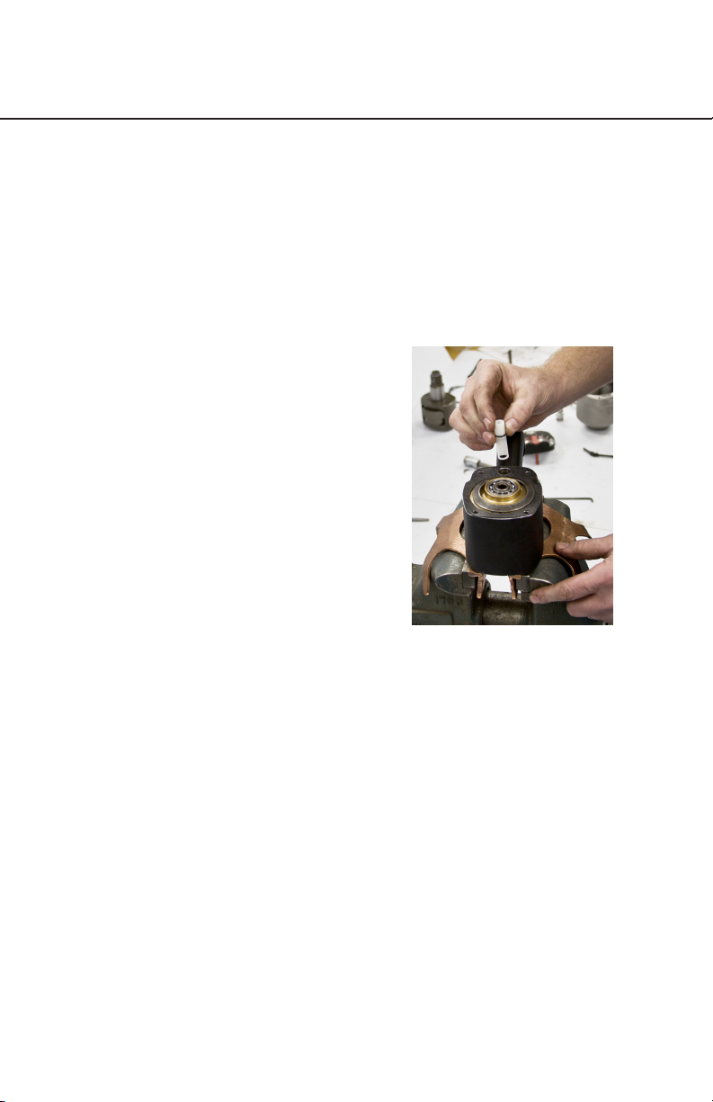
Disassembly of the
Impact Mechanism
Figure 16.2
Turn the Reverse Lever to top dead center,
or the twelve o’clock position before
removing Back Cap Bolts.
1. Turn the Reverse Lever
(750SS-16) to twelve o’clock
(see gure 16.2).
2. With the tool held securely in
a vice, unscrew and remove the
four Back Cap Bolts (750SS-12)
with a 5/32" Allen Wrench.
3. Lift the motor assembly off of
the Hammer Case (750SS-35)
and carefully set aside. Be sure
to hold the Back Cap (750SS-14)
in place so the motor does not
come out of the Motor Housing
(750SS-01).
4. Remove the Hammer Case
Gasket (750SS-34) and discard.
Disassembly
17
5. Remove the Hammer Case
and impact mechanism from
the vise. Remove the Hammer
Frame Washer (750SS-31) and
set aside.
6. Lift the Hammer Case off of
the impact mechanism. Remove
the Hammer Pins (750SS-33)
from the Hammer Frame (750SS-
31). Remove the Anvil from the
Hammer Frame by pulling up
and rotating the Anvil back and
forth. Remove the two Hammers
(750SS-32) from the Hammer
Frame paying careful attention to
the orientation of the Hammers.
Disassembly of the
Reverse Valve
1. Remove the four Back Cap
Bolts and lift the Back Cap from
the rear of the Motor Housing.
2. Remove the Back Cap Gasket
(750SS-13) and discard it.
3. Use a hook to gently pull the
Reverse Valve (750SS-28) from
the Reverse Valve Bushing
while paying close attention to
the orientation of the through
hole in the Reverse Valve. (see
gure 17.1).
4. Remove the O-ring (750SS-28)
from the Reverse Valve and
discard.
5. Using the thin blade of a
small at screwdriver, gently pry
the Reverse Lever Snap Ring
(750SS-17) from the Reverse
Lever. Remove the Reverse Lever
Spring (750SS-18). Set both
aside. Remove the Reverse Lever
from the Back Cap.
Figure 17.1
Using a hook to get it started, gently pull
the Reverse Valve from the Reverse Valve
Bushing.
Disassembly
18
Disassembly of the Motor
Assembly
1. Remove the four Back Cap
Bolts and the Back Cap. Remove
the Motor Clamp Washer
(750SS-19) and set aside.
2. Lift the Motor Housing
Assembly from the Impact
Mechanism. Use care to hold the
rear of the Motor so it does not
fall out.
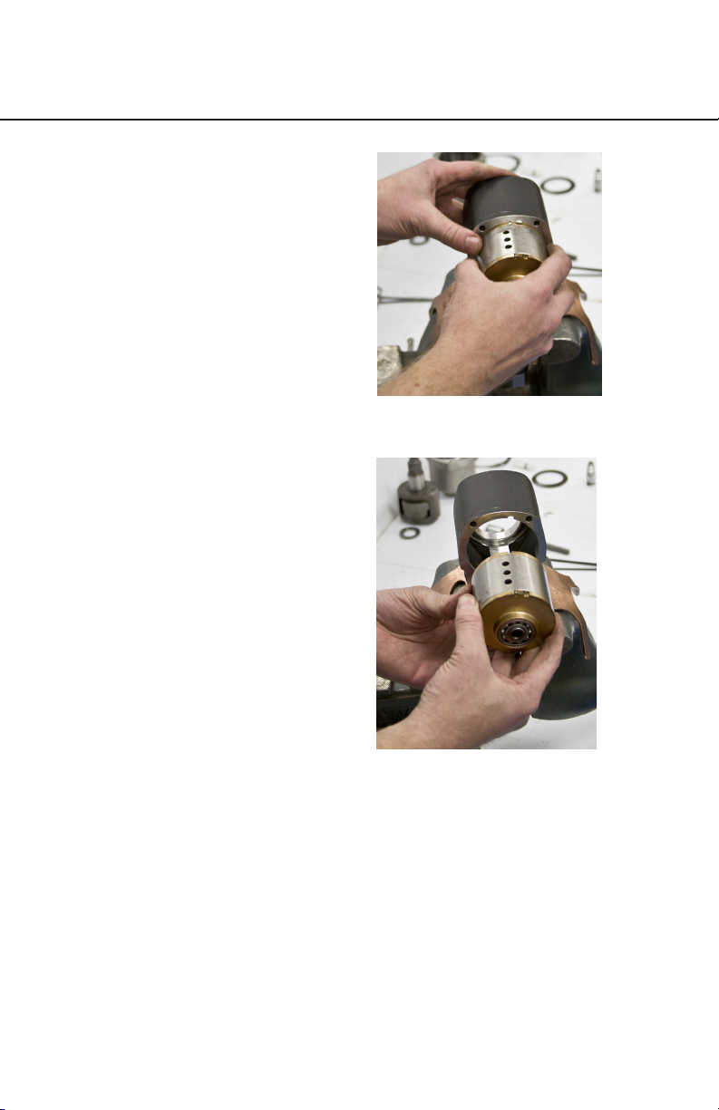
3. Gently nesse the entire
Motor Assembly from the rear of
the Motor Housing (750SS-01),
being careful not to lose the
Locating Pin (750SS-21A). (see
gures 18.1 and 18.2).
4. Place the entire Motor
Assembly on a clean rag with the
spline of the Rotor (750SS-22)
facing up. Remove the Front End
Plate (750SS-26) and Cylinder
(750SS-25). Remove the Vanes
(750SS-23) and Rear End Plate
(750SS-21) from the Rotor.
5. Inspect all Motor parts,
including the bearings (750SS-27
and 750SS-20) for damage or
wear and replace if needed.
Pay particular attention to the
integrity of the Cylinder Pins
(750SS-24), if they are collapsed
or damaged, replace.
Disassembly
Figure 18.2
Gently nesse the Motor Assembly out of
the rear of the Motor Housing.
NOTICE: Keep the motor as straight as
possible to ease removal.
Figure 18.1

19
Disassembly of the Motor
Housing
1. Hold the Motor Housing in a
vice using Copper Jaws. Clamp
against the front and rear of the
Housing (see gure 19.1).
NOTICE: Never clamp on the
sides of the Housing as damage
is likely to occur.
2. Using a 1" box wrench,
remove the Inlet Bushing
(750SS-07). Remove the O-ring
(750SS-08) from the Inlet
Bushing and discard. Remove
the Air Strainer Screen (750SS-
06), the Throttle Valve Spring
(750SS-05) and the Throttle Valve
(750SS-04) from the Housing and
set aside.
3. To remove the Throttle Valve
Seat (750SS-02), slide a at hook
under the seat and rmly pull up
(see gure 19.2).
4. Using internal snap ring
pliers, collapse and remove
the Retaining Ring (750SS-20).
Remove the Exhaust Deector
(750SS-11) using a pair of needle
nose pliers. Remove the Mufer
(750SS-09) from the Housing
and discard. Always use a new
Mufer for reassembly.
Figure 19.1
Always clamp the Motor Housing against
the front and rear of the Housing. Never
clamp against the sides of the housing as
damage can easily occur.
Figure 19.2
Slide a at hook under the Throttle Seat and
rmly pull up to dislodge it from the Motor
Housing.
Disassembly
20
General Instructions
1. When holding a tool in a vice
always use care and copper jaws
to protect the integrity of the part
that you are holding.
2. Prior to reassembly, clean
every part using a mild solvent
to remove all grease, oil, and
debris. Apply a thin layer of
recommended air tool oil to all
motor and throttle components
as you reassemble. Coat
the impact mechanism parts
with approximately 15 cc of
recommended grease. Apply a
thin lm of O-ring lubricant to all
O-rings before they are installed
on the part.
3. Check bearings to be sure
they are smooth. Push and pull
on the inner race as you turn it
while holding the outer race in
your opposite hand. If there is
any roughness noticed, replace
the bearing. Work a fair amount
of grease back into the bearing
whether reusing the old bearing
or replacing it with a new one.
4. Always press bearings by
using a drift and ONLY applying
pressure to the inner race of the
ball bearing when pressing onto
a shaft. Always press bearings by
using a drift and ONLY applying
pressure to the outer race when
pressing into a recess.
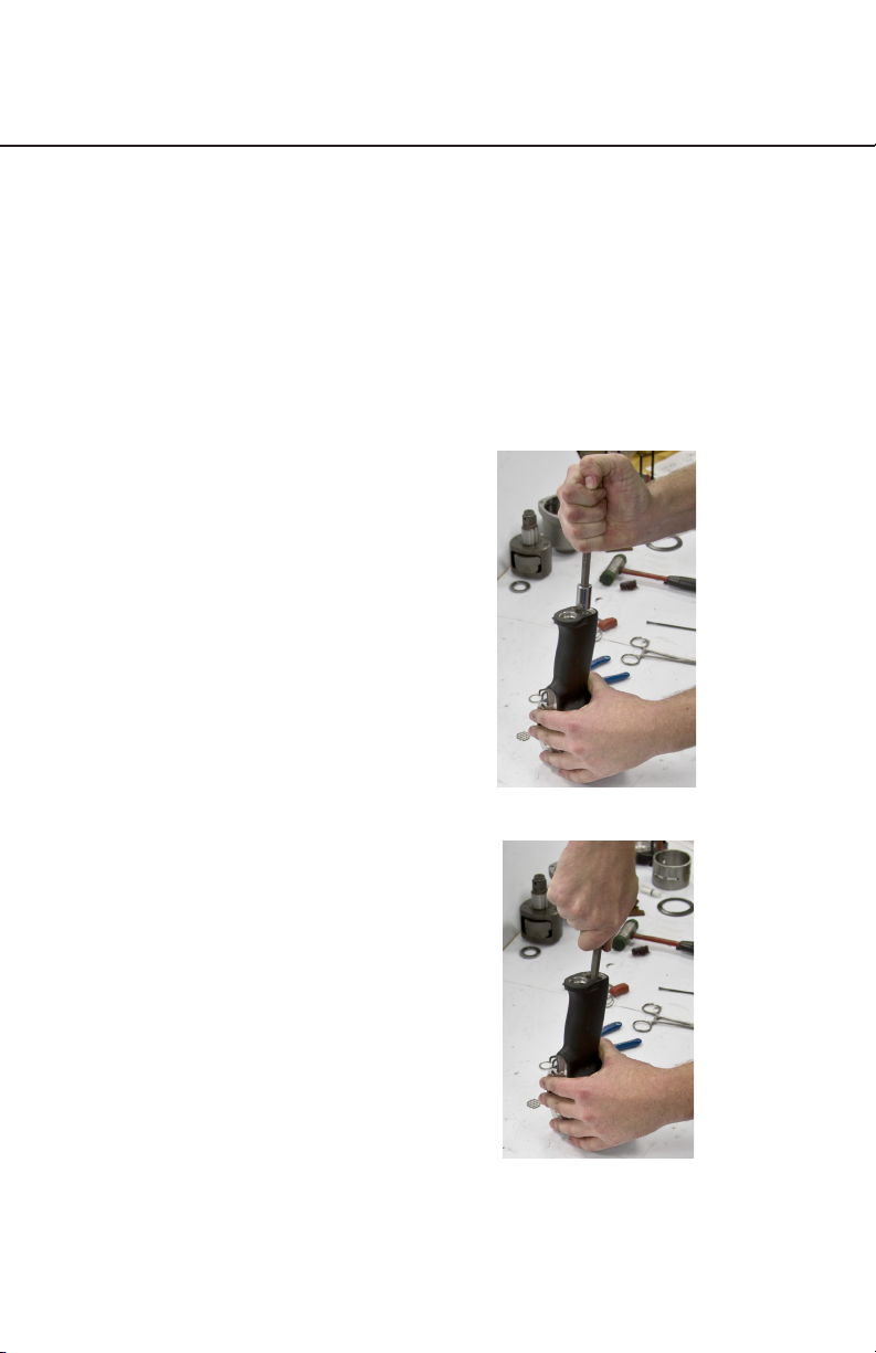
Assembly of the Motor
Housing
1. Install a new Throttle Valve
Seat by pushing it rmly into the
housing using a 13/16" drift. Be
sure that the Throttle Valve Seat is
seated all of the way down in its
recess (see gures 20.1 & 20.2).
Assembly
Figure 20.2
Using a 13/16" drift, rmly push the Throttle
Valve Seat into the housing. Be sure that it
is seated completely
Figure 20.1
This manual suits for next models
6
Table of contents
Popular Impact Driver manuals by other brands

Parkside
Parkside PDSSA 20-Li A1 Translation of the original instructions

Cornwell Tools
Cornwell Tools bluePOWER CAT3225A operating manual

Makita
Makita 6953 instruction manual

Stanley
Stanley Fat Max FMC041 Original instructions

Ingersoll-Rand
Ingersoll-Rand 235G Operation and maintenance manual

Makita
Makita 6904VH instruction manual


