Michigan Welding ACDC200LCD User manual

200A LCD AC/DC TIG WELDER
PART NO: ACDC200LCD (..172847)

2ACDC200LCD
CONTENTS
GENERAL SAFETY RULES...........................................................................................3
PROPER CARE, MAINTENANCE AND REPAIR..........................................................8
DESCRIPTION ..............................................................................................................9
INSTALLATION .............................................................................................................12
STICK (MMA) OPERATION..........................................................................................15
TIG (GTAW) OPERATION.............................................................................................20
TIG MAINTENANCE, SERVICE TIPS AND ADVICE ...................................................23
SERVICE, MAINTENANCE, TRANSPORTATION & STORAGE..................................26
TROUBLE SHOOTING CHART ....................................................................................28
MAIN CIRCUIT CHART ................................................................................................29
PARTS BREAKDOWN ..................................................................................................30
PARTS BREAKDOWN LIST..........................................................................................31
WARRANTY INFORMATION.......................................................................................32

3OPERATING MANUAL
SAVE THESE INSTRUCTIONS
GENERAL SAFETY RULES
WARNING: Read and understand all instructions.
Failure to follow all instructions listed below may result in serious injury.
CAUTION
!!
Do not allow persons to operate or assemble this ACDC200LCD
until they have read this manual and have developed a thorough
understanding of how the ACDC200LCD operates.
WARNING
!!
The warnings, cautions, and instructions discussed in this
instruction manual cannot cover all possible conditions or
situations that could occur. It must be understood by the operator
that common sense and caution are factors which cannot be built
into this product, but must be supplied by the operator.
IMPORTANT SAFETY CONSIDERATIONS
Your Welding Environment
•Keep the environment you will be welding in free from ammable materials.
•Always keep a re extinguisher close to your welding environment.
•Always have a qualied person install and operate this equipment.
•Make sure the area is clean, dry and well ventilated.
Do not operate the welder in humid, wet or poorly ventilated areas.
•Always have your welder maintained by a qualied technician in accordance
with local, state and national codes.
•Always be aware of your work environment. Be sure to keep other people,
especially children, away from you while welding.
•Keep harmful arc rays shielded from the view of others.
•Mount the welder on a secure bench or cart that will keep the welder secure and
prevent it from tipping over or falling.

4ACDC200LCD
Your Machine’s Condition
•Check ground cable, power cord and welding cable to be sure the insulation is not
damaged. Always replace or repair damaged components before using the welder.
•Check all components to ensure they are clean and in good operating condition
before use.
Use of Your Machine
•Do not operate the welder if the output cable, electrode, TIG torch, wire or wire
feed system is wet. Do not immerse them in water. These components and the
welder must be completely dry before attempting to use them.
•Follow the instructions in this manual.
•Keep welder in the o position when not in use.
•Connect ground lead as close to the area being welded as possible to ensure a
good ground.
•Do not allow any body part to come in contact with the welding wire/ller if you are
in contact with the material being welded, ground or rod/electrode from
another welder.
•Do not weld if you are in an awkward position. Always have a secure stance while
welding to prevent accidents. Wear a safety harness if working above ground.
•Do not drape cables over or around your body.
•Wear a full coverage helmet with appropriate shade (see ANSI Z87.1 safety
standard) and safety glasses while welding.
•Wear proper gloves and protective clothing to prevent your skin from being
exposed to hot metals, UV and IR rays.
•Do not overuse or overheat your welder. Allow proper cooling time
between duty cycles.
•Keep hands and ngers away from moving parts and stay away from the drive rolls.
•Do not point welding torch at any body part of yourself or anyone else.
•Always use this welder in the rated duty cycle to prevent excessive heat and failure.
5OPERATING MANUAL
Specic Areas of Danger, Caution or Warning
Electrical Shock
•Electric arc machines can produce a shock that can cause injury or
death. Touching electrically live parts can cause fatal shocks and
severe burns. While welding, all metal components connected to the
wire are electrically hot. Poor ground connections are a hazard, so
secure the ground lead before welding.
•Wear dry protective apparel: coat, shirt, gloves and insulated footwear.
•Insulate yourself from the work piece. Avoid contacting the work piece
or ground.
•Do not attempt to repair or maintain the welder while the power is on.
•Inspect all cables and cords for any exposed wire and replace
immediately if found.
•Use only recommended replacement cables and cords.
•Always attach ground clamp to the work piece or work table as close
to the weld area as possible.
•Do not touch the welding wire/rod or electrode and the ground or
grounded work piece at the same time.
•Do not use a welder to thaw frozen pipes.
Fumes and Gases
•Fumes emitted from the welding process displace clean air and can
result in injury or death.
•Do not breathe in fumes emitted by the welding process. Make sure
your breathing air is clean and safe.
•Work only in a well-ventilated area or use a ventilation device to remove
welding fumes from the environment where you will be working.
•Do not weld on coated materials (galvanized, cadmium plated or
containing zinc, mercury or barium). They will emit harmful fumes that
are dangerous to breathe. If necessary use a ventilator, respirator with
air supply or remove the coating from the material in the weld area.
•The fumes emitted from some metals when heated are
extremely toxic. Refer to the material safety data sheet for
the manufacturer’s instructions.
•Do not weld near materials that will emit toxic fumes when heated.
Vapours from cleaners, sprays and degreasers can be highly toxic
when heated.

6ACDC200LCD
UV and IR Arc Rays
•The welding arc produces ultraviolet (UV) and infrared (IR) rays that
can cause injury to your eyes and skin. Do not look at the welding arc
without proper eye protection.
•Always use a helmet that covers your full face from the neck to top of
head and to the back of each ear.
•Use a lens that meets ANSI standards and safety glasses. For welders
under 160 Amps output, use a shade 10 lens; for above 160 Amps, use
a shade 12. Refer to the ANSI standard Z87.1 for more information.
•Cover all bare skin areas exposed to the arc with protective clothing
and shoes. Flame-retardant cloth or leather shirts, coats, pants or
coveralls are available for protection.
•Use screens or other barriers to protect other people from the arc rays
emitted from your welding.
•Warn people in your welding area when you are going to strike an arc
so they can protect themselves.
Fire Hazards
•Do not weld on containers or pipes that contain or have had
ammable, gaseous or liquid combustibles in them. Welding creates
sparks and heat that can ignite ammable and explosive materials.
•Do not operate any electric arc welder in areas where ammable or
explosive materials are present.
•Remove all ammable materials within 10m of the welding arc.
If removal is not possible, tightly cover them with reproof covers.
•Take precautions to ensure that ying sparks do not cause res or
explosions in hidden areas, cracks or areas you cannot see.
•Keep a re extinguisher close in the case of re.
•Wear garments that are oil-free with no pockets or cus that will
collect sparks.
•Do not have on your person any items that are combustible, such as
lighters or matches.
•Keep work lead connected as close to the weld area as possible to
prevent any unknown, unintended paths of electrical current from
causing electrical shock and re hazards.

7OPERATING MANUAL
Hot Materials
•Welded materials are hot and can cause severe burns if handled
improperly.
•Do not touch welded materials with bare hands.
•Do not touch welding torch nozzle after welding until it has had time
to cool down.
Sparks/Flying Debris
•Welding creates hot sparks that can cause injury. Chipping slag o
welds creates ying debris.
•Wear protective apparel at all times: ANSI-approved safety glasses or
shield, welder’s hat and ear plugs to keep sparks out of ears and hair.
Electromagnetic Field
•Electromagnetic elds can interfere with various electrical and
electronic devices such as pacemakers.
•Consult your doctor before using any electric arc welder or cutting
device
•Keep people with pacemakers away from your welding
area when welding.
•Do not wrap cable around your body while welding.
•Wrap welding torch and ground cable together whenever possible.
•Keep welding torch and ground cables on the same side of your body.
Shielding Gas Cylinders Can Explode
•High pressure cylinders can explode if damaged, so treat them carefully.
•Never expose cylinders to high heat, sparks, open ames, mechanical
shocks or arcs.
•Do not touch cylinder with welding torch.
•Do not weld on the cylinder
•Always secure cylinder upright to a cart or stationary object.
•Keep cylinders away from welding or electrical circuits.
•Use the proper regulators, gas hose and ttings for
the specic application.
•Do not look into the valve when opening it.
•Use protective cylinder cap whenever possible

8ACDC200LCD
PROPER CARE, MAINTENANCE AND REPAIR
WARNING
!!
Always have power disconnected when working
on internal components.
Do not touch or handle PC board without being properly
grounded with a wrist strap. Put PC board in static proof bag to
move or ship.
Do not put hands or ngers near moving parts such as drive
rolls of fan.
ACDC200LCD Use and Care
Do not modify the ACDC200LCD in any way. Unauthorized modication may impair
the function and/or safety and could aect the life of the equipment. There are
specic applications for which the ACDC200LCD was designed.
•Always check of damaged or worn out parts before using the ACDC200LCD.
Broken parts will aect the ACDC200LCD operation. Replace or repair damaged
or worn parts immediately.
•When ACDC200LCD is not in use, store it in a secure place out of the reach of
children. Inspect it for good working condition prior to storage and before re-use.
Caring for the Environment
When a tool is no longer usable it should not be disposed of with household waste,
but in an environmentally friendly way. Please recycle where facilities exist. Check
with your local council authority for recycling advice.
Recycling packaging reduces the need for landll and raw materials. Reuse of recycled
material decreases pollution in the environment. Please recycle packaging where
facilities exist. Check with your local council authority for recycling advice.
Transport and Storage
•Hold the handle or the bottom to move it.
•The machines should be rmly secured during transportation.
•The machines should be stored out of the rain.

9OPERATING MANUAL
DESCRIPTION
The ACDC200LCD series is digitally controlled
machine which can be used for STICK, AC TIG,
DC TIG & PULSE TIG welding. This unit uses
1~Phase 240V, 50/60HZ AC power.
Specications and Dimensions
Item ACDC200LCD
Input voltage 240V (220 ~ 240)
Frequency 50/60Hz
Rated input current TIG: 28A, STICK: 31A
Rated input capacitance 8.7KVA
No-load voltage 71V
Rated working voltage TIG: 18V, STICK: 26.8V
STICK welding current 10 ~ 170A
DC TIG welding current 10 ~ 200A
AC TIG welding current 10 ~ 200A
Start Amps 10 ~ 200A
End Amps 10 ~ 200A
Up slope 0 ~ 10s
Down slope 0 ~ 10s
Base Amps 10 ~ 200A
Pulse frequency 0.1 ~ 200Hz
Pulse ratio 5 ~ 95%
AC Balance 10 ~ 50%
AC Frequency 50 ~ 160Hz
Pre ow 0.3 ~ 20s
Post ow 0.3 ~ 20s
Rated duty cycle 15%
10min/100% TIG: 66A, STICK: 54A
Eciency 56.9% η
Power factor 0.75 Cosφ
Insulation class H
Enclosure protection IP21S
Cooling type Fan cooled
Dimension 563x251x374 (L×W×Hmm)
Weight 20.5kg

10 ACDC200LCD
Front Control Panel
1
2
3
4
1. LCD Screen: When the machine is turned on, this LCD will illuminate showing the
parameters of the selected mode.
2. Process: Toggles between welding modes: STICK, AC TIG, AC TIG PULSE, DC TIG,
DC TIG PULSE
3. Select Knob: Toggles between the dierent parameters, press and turn to adjust
selected parameter.
4. 2T/4T select/ Save/Load: Switches between 2T & 4T. Press and hold will give the
ability to load pre-set parameters.
Parameters
This part is to show the procedure, when the indicator lights, the corresponding
parameter can be adjusted with the select knob. See following details:
1
2
3
4
56
7
8
910
11 12

11OPERATING MANUAL
1. Pre ow time (0.3 – 20 Seconds)
2. Starting Amperage (10 – 200A)
3. Up-slope time – (0 – 10 Seconds)
4. Peak Amperage TIG (10 – 200A) STICK (10-170A)
5. Base Amperage (10 – 200A Pulse only)
6. Down-slope time – (0 – 10 Seconds)
7. Ending Amperage (10 – 200A)
8. Post ow time (0.3 - 20 Seconds)
9. Pulse Frequency (0.1 – 200 Hz)
10. Pulse Ratio (5 -95 %)
11. AC Frequency (50 – 160 Hz)
12. AC Balance (10 – 50 %)
Unpacking
1. Remove cartons, bags or Styrofoam containing the welder and accessories.
2. Check the contents with the packing list below.
Item QTY
ACDC inverter power source 1 unit
Argon regulator 1pc
5m 26 series premium TIG torch 1pc
3m twist-lock electrode holder 1pc
3m earth clamp 1pc
4m gas hose 1pc
TIG torch accessories pack inc:
Tungsten, long & short cap, 6,8 & 10 alumina, collet
and collet body suit 1.6 & 2.4mm tungstens
1pc
Operator’s Manual 1pc
3. After unpacking unit, inspect carefully for any damage that may have occurred
during transit. Check for loose, missing, or damaged parts. Shipping damage
claim must be led with carrier.

12 ACDC200LCD
INSTALLATION
Machine Setup
Earth
Clamp
Positive
Socket
Foot Pedal
Socket
Negative
Socket
TIG
Torch
Foot
Pedal* *additional extra
TIG torch gas
connection
Power Requirement
AC single phase 240V, 50/60 Hz fused with a suitable time delayed fuse or circuit
breaker is required
WARNING
!
High voltage danger from power source! Consult a qualied
electrician for proper installation of receptacle. This welder must be
grounded while in use to protect the operator from electrical shock.
Do not remove grounding prong or alter the plug in any way. Do
not use any adapters between the welder’s power cord and the
power source receptacle. Make sure the POWER switch is OFF
when connecting your welder’s power cord to a properly grounded
240Vac, 50/60Hz, single phase power source.
Extension Cord
It is strongly recommended that an extension cord should not be used because of the
voltage drop they produce. This drop in voltage can aect the performance of the welder.
If you need to use an extension cord must use conductors of at least 6mm2and less than
8m length.

13OPERATING MANUAL
Setting Up The Work Piece
Welding positions
There are two basic positions, for welding: Flat
and Horizontal. Flat welding is generally easier,
faster, and allows for better penetration. If
possible, the work piece should be positioned so
that the bead will run on a at surface.
Preparing the joint
Before welding, the surface of work piece needs to be free of dirt, rust, scale, oil or
paint. Or it will create brittle and porous weld. If the base metal pieces to be joined
are thick or heavy, it may be necessary to bevel the edges with a metal grinder. The
correct bevel should be around 60 degrees.
See following picture:
Based on dierent welding position, there are dierent welding joint, see following
images for more information
14 ACDC200LCD
Earth Clamp Connection
Connect the earth clamp cable to the positive terminal on the front of the machine,
and the clamp to the work piece. Clear any dirt, rust, scale, oil or paint on the earth
clamp. Make certain you have a good solid ground connection. Make sure the earth
clamp touches the metal.
Gas Installation
WARNING
!!
Shielding gas cylinders and high pressure cylinders can explode
if damaged, so treat them carefully.
• Never expose cylinders to high heat, sparks, open ames,
mechanical shocks or arcs.
• Do not touch cylinder with TIG torch.
• Do not weld on the cylinder.
• Always secure cylinder upright to a cart or stationary object.
• Keep cylinders away from welding or electrical circuits.
• Use the proper regulators, gas hose and ttings for
the specic application.
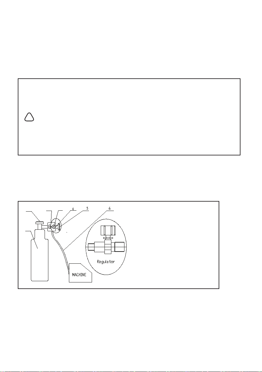
The gas hose
The gas hose, regulator and gas cylinder connection is shown below. Attach one end
of the gas hose to the gas solenoid valve (gas inlet) located on the back panel of the
welder. Attach the other end to the gas regulator which is attached to the shielding
gas cylinder. See illustration below:
1 Cylinder valve: Controls GAS
CYLINDER gas ow.
2 Cylinder pressure gauge
3 Gas ow gauge, see set up charts
for recommended settings
4 Regulator
5 Adjustment knob controls gas
pressure to the welder.
6 Gas hose
7 Gas cylinder
7
3
2
1
NOTE: Slowly open the cylinder valve by turning it counter-clockwise until the
cylinder pressure gauge registers on the rst gauge of the regulator. Turn the
adjustment knob clockwise (right) slowly to increase gas ow (check the set up
guide on the machine for guidelines on gas ow. To reduce the gas ow, turn the
adjustment counter-clockwise (left). The gas valve is located on the back panel of the
welder and activated by the trigger. Gas ow should be heard when the trigger is
activated. Avoid unnecessary gas loss by closing the tank valve when
nished welding.

15OPERATING MANUAL
STICK MMA OPERATION
Electrode
The welding electrode is a rod coated with a layer of ux. When welding, electrical
current ows between the electrode (rod) and the grounded metal work piece.
The intense heat of the arc between the rod and the grounded metal melts the
electrode and the ux. The most popular electrodes are:
•E6011 60,000 PSI tensile strength deep penetrating applications.
•E6013 60,000 PSI tensile strength used for poor t up applications
•E7014 70,000 PSI tensile strength used for high deposition and fast travel speeds
with light penetration
•E7018 70,000 PSI tensile strength, used for out of position and tacking.
Selecting The Proper Amperage For The Electrode
There is no golden rule that determine the exact rod or heat setting required for
every situation. The type and thickness of metal and the position of the work piece
determine the electrode type and the amount of heat needed in the welding process.
Heavier and thicker metals required more amperage.
Electrode/Amperage Guide
2.5mm diameter E6013 Electrodes – 60 to 100amps
3.2mm diameter E6013 Electrodes – 80 to 150amps
It is best to practice your welds on scrap metal which matches the metal you intend to
work with to determine correct heat setting and electrode choice. See the following
trouble shooting tips to determine if you are using a correct electrode.
1. When proper rod is used:
a) The bead will lay smoothly over the work without ragged edges
b) The base metal puddle will be as deep as the bead that rises above it
c) The welding operation will make a crackling sound similar to the sound of
bacon frying
2. When a rod too small is used
a) The bead will be high and irregular
b) The arc will be dicult to maintain
3. When the rod is too large
a) The arc will burn through light metals
b) The bead will undercut the work

16 ACDC200LCD
c) The bead will be at and porous
d) Rod may be freeze or stick to work piece
Note: Rate of travel over the work also aects the weld. To ensure proper penetration
and enough deposit of rod, the arc must be moved slowly and evenly along the weld
seam.
1
2
3
Electrode holder connection
1. Attach the Twist-lock electrode holder to the +ve terminal on the ACDC200LCD
2. Open the electrode holder by turning the head and handle in the opposite
directions until the head clamp opens.
3. Place the exposed end of the electrode into the lead clamp and hold in place.
4. Turn the handle to close the head clamp.
Setting the amperage control
The welder has an innite output current control.
There is no golden rule that determines the exact amperage required for every
situation. It is best to practice your welds on scrap metal which matches the metals
you intend to work with to determine correct setting for your job. The electrode type
and the thickness of the work piece metal determine the amount of heat needed in
the welding process. Heavier and thicker metals require more voltage (amperage),
whereas lighter and thinner metals require less voltage (amperage).
Electrode/Amperage Guide
2.5mm diameter E6013 Electrodes – 60 to 100amps
3.2mm diameter E6013 Electrodes – 80 to 150amps

17OPERATING MANUAL
Welding techniques
The best way to teach yourself how to weld is with short periods of practice at regular
intervals. All practice welds should be done on scrap metal that can be discarded.
Do not attempt to make any repairs on valuable equipment until you have satised
yourself that your practice welds are of good appearance and free of slag or gas
inclusions.
Holding the electrode
The best way to grip the electrode holder is the way that feels most comfortable to
you. To Position the Electrode to the work piece when striking the initial arc, it may
be necessary to hold the electrode perpendicular to the work piece. Once the arc is
started the angle of the electrode in relation to the work piece should be between
10 and 30 degrees. This will allow for good penetration, with minimal spatter.
Striking the arc
WARNING
!
EXPOSURE TO A WELDING ARC IS EXTREMELY HARMFUL TO THE
EYES AND SKIN.
Never strike an arc or begin welding until you have adequate
protection. Wear ame proof welding gloves, heavy long-sleeved
shirt, trousers without turn-ups, safety shoes and a welding
helmet or face mask.
Scratch the work piece with the end of electrode to start
arc and then raise it quickly about 3.2mm gap between
the rod and the work piece. See picture (right).
It is important that the gap be maintained during the
welding process and it should be neither too wide or too
narrow. If too narrow, the rod will stick to the work piece.
If too wide, the arc will be extinguished. It needs much
practice to maintain the gap. Beginners may usually get
sticking or arc extinguishing. When the rod sticks to
the work piece, gently rock it back and forth to make
them separate. If not, the circuit is shorted, and it will
overload the welder. A good arc is accompanied by a
crisp, cracking sound. The sound is similar to that made
by eggs frying. To lay a weld bead, only 2 movements
are required; downward and in the direction the weld is
to be laid, as in following gure:
1/8"
3.2mm

18 ACDC200LCD
Types of weld bead
The following paragraphs discuss the most commonly used arc welding beads.
The STRINGER BEAD is formed by traveling with the electrode in a straight line
while keeping it centred over the weld joint.
The WEAVE BEAD is used when you want to deposit metal over a wider space
than would be possible with a stringer bead. It is made by weaving from side to
side while moving with the electrode. It is best to pause momentarily at each side
before weaving back the other way to improve penetration.
Welding position
FLAT POSITION is the easiest of the welding positions and is most commonly
used. It is best if you can weld in the at position if at all possible as good results
are easier to achieve.

19OPERATING MANUAL
The HORIZONTAL POSITIONS are performed very much the same as the at weld except
that the angle is dierent such that the electrode, and therefore the arc force, is directed
more toward the metal above the weld joint. This more direct angle helps prevent the
weld puddle from running downward while still allowing slow enough travel speed to
achieve good penetration. A good starting point for your electrode angle is about 30
degrees DOWN from being perpendicular to the work piece.
How to judge a good weld bead
When the trick of establishing and holding an arc has been perfected, the next step is
learning how to run a good bead. The rst attempts in practice will probably fall short
of acceptable weld beads. Too long of an arc will be held or the travel speed will vary
from slow to fast (see following):
1 2 3
4
1. Weld speed is too fast.
2. Weld speed is too slow.
3. Arc is too long.
4. Ideal weld.
A solid weld bead requires that the electrode be moved slowly and steadily along
the weld seam. Moving the electrode rapidly or erratically will prevent proper fusion
or create a lumpy, uneven bead. To prevent ELECTRIC SHOCK, do not perform any
welding while standing, kneeling, or lying directly on the grounded work.
How to nish the bead
As the coating on the outside of the electrode burns o, it forms an envelope of
protective gasses around the weld. This prevents air from reaching the molten metal
and creating an undesirable chemical reaction. The burning coating, however, forms
slag. The slag formation appears as an accumulation of dirty metal scale on the
nished weld. Slag should be removed by striking the weld with a chipping hammer.

20 ACDC200LCD
TIG GTAW OPERATION
When connecting torches, ensure the machine is o and the supply cable is unplugged.
TIG welding is done in DC EN set up. The ground/earth cable connects to the positive
(+) terminal. The torch cable connects to the negative terminal.
TIG welding requires an ARGON gas supply. Connect the gas hose from the Lift TIG
torch to a regulator axed to an ARGON gas supply.
Ensure the correct tungsten (check for dia and type) is installed on the Lift TIG torch
and set up correctly.
Installation
Depending on the application, the correct collet, collet body, gas cup, electrode and
electrode tip conguration should be tted (See tables on next page)
L
L = 1/3D
For general use on AC
D
LL = D
For general use on DC
D
LL= D x 2
For DC below 20A
D
After initial strike the electrode
will form a domed prole
You are now ready to connect the torch to the power source and gas supply. Once
connected check you have adequate gas ow.
Operation
Once the installation guidelines have been followed you are ready to weld.
When using the torch do not exceed its published current carrying capacity and duty
cycle rating.
Table of contents
Other Michigan Welding Welding System manuals


