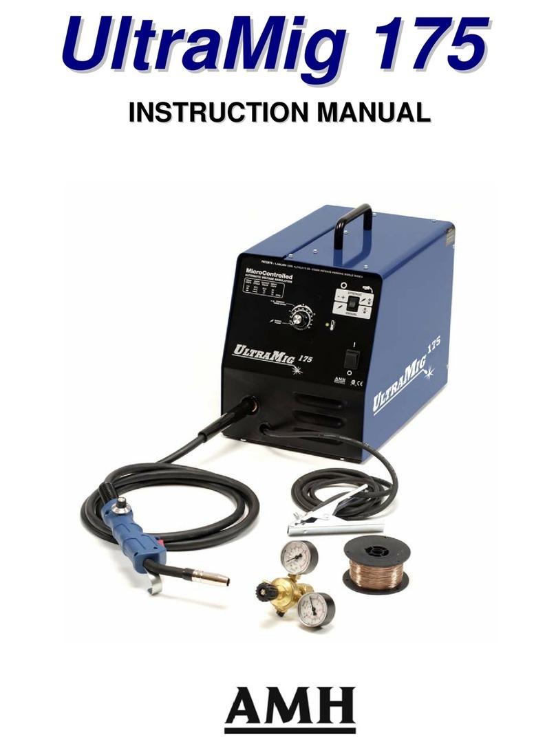
AMH ULTRAMIG 200 User manual


Thank you for choosing AMH Canada’s ULTRAMIG 200 INVERTER. Our welders are of high safety,
reliability, durability and convenient maintenance, as well as excellent welding efficiency. This user’s manual
contains important information about safe installation, operation and maintenance of this product. For welder’s
technical parameters, please refer to technical parameter in this manual. Please read this manual carefully
before operate. In order to ensure the operator’s safety and a reliable working environment, please pay
attention the safety tips and operate according to the instructions. For more AMH Canada products, please
contact AMH Canada headquarters,authorized dealers, or visit our website: http://www.amh.ca.
Declaration
AMH Canada Ltd: We hereby solemnly declare that all products are manufactured according to relative GB
or ISO standard, and conform to IEC60974-1 international safety standard.
All products purchased from our company are covered for one-year defect liability period, starting from the
purchasing day on the contract.
Please read this manual carefully before operation:
1. AMH Canada make every effort to achieve the full accuracy and data integrity of this manual’s
content; AMH Canada assume no liability and responsibility for any nonconforming operation to
this manual.
2. Copyright by AMH Canada Ltd. All rights are reserved. AMH Canada reserves the right to modify
this manual without prior notice.
3. Though contents in this manual have been carefully checked, inaccuracies might still exist. Thank you
for contacting us in case of any inaccuracy you may discover in this manual.
4. Any unauthorized copy, record, reprint or spread of the contents in this manual is prohibited.
5. This manual was released in April, 2021.
AMH Canada LTD.
Address: 391, St-Jean-Baptiste Est, Rimouski (Québec) CANADA
Postcode: G5L 1Z2
Tel: 418-724-4105
Website: http://www.amh.ca
E-mail: [email protected]
Notes:
To avoid any loss and personal injury, please pay special attention to all “NOTE!”.
Please read this manual carefully before operation.

Contents
1.Safety-------------------------------------------------------------------------------------------------------------------------- 1
2.Symbol Description -------------------------------------------------------------------------------------------------------- 2
3.Functions --------------------------------------------------------------------------------------------------------------------- 3
4. Performance Features ---------------------------------------------------------------------------------------------------- 3
5.Technical Parameters ------------------------------------------------------------------------------------------------------ 4
6. Operation Description ---------------------------------------------------------------------------------------------------- 6
7.Installation & Commission & Operation ------------------------------------------------------------------------------ 7
7.2 Gas Shielded Welding Installation and Operation ----------------------------------------------------------------9
7.3 Gasless Shielded Welding Installation and Operation---------------------------------------------------------- 10
8.Precautions----------------------------------------------------------------------------------------------------------------- 11
9. Basic Knowledge of Welding ------------------------------------------------------------------------------------------ 12
10. Maintenance------------------------------------------------------------------------------------------------------------- 21
11. Troubleshooting -------------------------------------------------------------------------------------------------------- 22
APPENDIX A: Packing, Transportation, Storage------------------------------------------------------------------- 24
APPENDIX B: WIRING DIAGRAM OF COMPLETE MACHINE-------------------------------------------- 25
7.1 MMA Installation and Operation 7
8.2 Safety Tips 11
8.1 Working Environment 11
9.3 Multi-positional Welding 20
9.2 GMAW 15
9.1 MMA 12
A.3 Storage 24
A.2 Transportation - 24
A.1 Packing 24

1. Safety
Welding may cause damage to you and others. Please take good protection during welding. Please refer to the
operator safety guidelines in conformity with the accident prevention requirements of the manufacturer for more
details.
Only qualified personnel can operate this machine!
Please use welding protection appliances approved by national safety
supervision department.
All operators must be licensed and valid special operating personnel for
metal welding & cutting jobs.
Please cut off power supply while maintaining.
Electric shock-may result in serious injury or even death!
Install grounding device according to application standard.
Do not touch live parts with naked skin, wet gloves or wet clothes.
Be sure you are insulated from ground and work piece.
Make sure all your working conditions are safe
Fume and gases can be dangerous!
Keep your head away from fumes and gases while in welding.
Please use enough ventilation or exhaust to keep fumes and gases away
from the breathing zone.
Arc rays can burn!
Use suitable shield and clothing to protect your eyes and body.
Protect other nearby personnel with suitable, non-flammable screening
from being injured.
Improper operation may cause fire or explosion.
Welding spark may cause fire. Please make ensure there are no
inflammables in welding area, and always be alert to fire safety.
Make sure there is fire extinguisher readily available and welders are
well trained to operate the fire extinguisher.
Do not weld air-tight container.
Do not use this machine for pipe unfreezing
Weld materials can burn.
Do not touch hot work piece with bare hands.
Cool the welding torch after continuously working.
1

Excessive noise can be harmful to hearing.
Wear ear covers or other hearing protectors when welding.
Give warning to nearby personnel that noise may be potentially
hazardous to hearing.
Magnetic field can be harmful to pacemakers.
Electric current flowing through any conductor creates electric and
magnetic fields. Welders having peacemakers should consult their
doctor before operating this equipment.
Moving parts may injure your body.
Please keep away from moving parts (such as fan).
All door, panel, cover, baffle plate, and other protective device should
be closed and well located.
Asking for professional support while trouble strikes.
When trouble strikes in installation and operation, please resort to this
manual for according contents.
If you are still in lost, or you still cannot solve the problem, please
contact the AMH Canada dealer or the service center for professional
support.
2. Symbol Description
Cautions in operation
Items need special instruction
It’s forbidden to dispose electric waste with
other ordinary waste. Please take care of our
environment.
2

3. Function Description
Multi-function Design
MMA/MIG are available
Integrated trolley
Spool gun
FCAW
4. Performance Features
Advanced IGBT inverter technology
20-33KHz inverting frequency greatly reduces welder’s size and weight
Great reduction in copper and iron loss greatly enhances the welding efficiency and saves energy.
Switching frequency is beyond audio frequency, which almost eliminates noise pollution.
Leading control mode
It can be welded with various electrodes with a diameter of 0.6mm~1.2mm, and it can bewidely
used in acid and basic electrode welding.
Easy arc starting, less spatter, stable current and good shaping.
Nice shape and structure design
Metal enclosure can withstand strong shock and drop and guarantee high work efficiency even in
harsh working environment.
Excellent insulating property.
Waterproof, antistatic and anticorrosion.
3

5. Main Technical Parameters
MODEL ULTRAMIG 200 INVERTER
Input power supply Single-phase AC220V-240V, 50/60Hz
Rated input capacity (KVA) 8.8
Rated output current (A) 200
Rated output voltage (V) 24
Rated duty cycle (%) 35
No-load voltage (V) 52
Output current range in MMA (A) 10~200
Output current range in MIG (A) 30~200
Output voltage range in MIG (V) 11~27
Electrode diameter applicable (mm) 0.6/0.8/0.9/1.0
Wire spool applicable (kg) 15
Wire feed speed range (m/min) 1.5~16
Insulation class F
Cooling mode Air-cooling
Protection class IP21S
Power factor 0.7
Efficiency (%) 85
Size (mm) 900X450X755
Weight (Kg) 46
6. ※Note!: ①Tested under 40℃working environment.
4

6. Operation Description
1
2
3
4
5
6
7
8
9
1. VRD LED
2. Power LED
3. Overheating LED
16 4. Voltage meter
15 5. Manual wire feeding button
6. Voltage control knob in MIG
7. Wire feed speed control knob in MIG
8. Inductance control knob
13 9. European connector of the welding torch in
MIG
12 10. Socket of wire pull torch control cable
11. “-” output terminal
12. “+” output terminal
11 13. MMA/MIG switch
14. Push/Pull torch switch
10 15. 2T/4T switch
16. Current control knob in MMA
17. Current meter
5
1
1

18
19
20
21
22
18. Power switch
19. Input power cord
20. Socket of gas regulator heater
21. Fan
22. Gas inlet
23. Burn back time
6

7. Installation, Debugging & Operation
Notice: Please install the machine strictly according to the following steps.
Turn off the power supply before any electric connection operation.
IP21S enclosure protection grade, please do not operate it in rain.
7.1 MMA Installation
Fig 6 MMA Sketch Map
1. Please connect the primary power line to the according voltage class. Please make sure the power
7
24.Spool
25.Wire feeder
26.Euro connector
24
26
25

line is connected to the right voltage class.
2. Please make sure the primary source is in fine contact with the according power line terminal or
socket and prevent oxidation.
3. Please measure the voltage with multi-meter and check if it’s in the fluctuation range.
4. Please insert the earth clamp cable plug into the front panel’s below position “+” socket, and
screwtightly clockwise.
5. Please insert the electrode holder cable plug into the front panel’s upper position ”-“ socket
andscrew tightly clockwise.
6. Please make sure the supply is in good earthing condition.
7.1.1 Operation
1) After the correct installation per above methods, please turn on the power switch(“ON”). While the power
supply is “ON”, welder starts to work normally with indicator lighting up and fan working.
2) Please pay attention to the polarity while connecting. There are normally two ways of wiring: DCEP and DCNP.
DCNP: welding holder connected to “-“and work piece to “+”;DCEP: workpiece to “-“and welding holder to
“+”. Please choose the proper connection method according to different workpiece and processing methods.
Unstable arc, spatter, and electrode sticking could happen if improper polarity is selected. Please change the
quick connect plug to change the polarity in case of above abnormal situation.
3) When switching the welding mode to MMA, welding can be carried out with output current in rated range.
4) Select guide line with larger cross-section to reduce the voltage drop if the welder and workpiece distance is
too far and secondary cables (welding cable and earth cable) are long.
5) Preset the welding current according to electrode type and size; clamp the electrode and then welding can be
carried out by short circuit arc ignition.
For welding parameters, please refer to the below table.
7.1.2 Welding parameters table (for reference only)
Electrode Diameter
(mm)
Recommended Welding Current
(A)
Recommended Welding Voltage
(V)
1.0
20~60
20.8~22.4
1.6
44~84
21.76~23.36
2.0
60~100
22.4~24.0
2.5 80~120 23.2~24.8
3.2 108~148 23.32~24.92
4.0 140~180 24.6~27.2
5.0 180~220 27.2~28.8
6.0 220~260 28.8~30.4
8

Note: This table is suitable for mild steel welding. For other materials, please consult related materials and
welding processing manual.
7.2 Gas Shielded Welding Installation and Operation
7.2.1 Installation:
1) Insert the welding torch into the front panel’s “Euro connector for torch” output socket and tighten it. After
install the wire spool, pull through the welding wire into the torch body.
2) Connect the cylinder equipped with the gas regulator to the gas inlet on the back panel of the machine with a
gas hose.
3) Insert the cable plug with earth clamp into the front panel’s“-” output terminal and tighten it clockwise.
4) Insert the front panel’s quick plug into “+” output terminal and tighten it clockwise.
5) Install the wire spool on the spindle adapter, ensuring that the groove size in the feeding position on the drive
roll matches the contact tip size of the welding torch and the wire size being used. Release the pressure arm
of the wire feeder to thread the wire through the guide tube, and into the drive roll groove. Adjust the pressure
arm, ensuring no sliding of the wire. Too high pressure will lead to wire distortion, which will affect wire
feeding. Press the inching wire feeding button to thread the wire out of the torch contact tip.
Installation Sketch Map:
Fig7 Gas Shielded Welding Sketch Map
7.2.2 Operation:
1) After the correct installation per above methods, please turn on the power switch. While the power supply is
“ON”, welder starts to work normally with the indicator lighting up and fan working.Open the cylinder valve,
9

and adjust the flow regulator to get the proper gas flow.
2) Preset the wiring feeding speed and welding voltage according to workspace’s thickness and electrode
diameter.
7.3 Installation and operation of gasless self-shielded metal arc welding
7.3.1Installation
1) Insert the welding torch into the front panel’s “Euro connector for torch” output socket and tighten it. After
install the wire spool, pull through the welding wire into the torch body.
2) Insert the cable plug with earth clamp into the front panel’s“+” output terminal and tighten it clockwise.
3) Insert the quick plug of the wire feeder into the front panel’s “-” output terminal and tighten it clockwise.
4) Install the wire spool on the spindle adapter, ensuring that the groove size in the feeding position on the drive
roll matches the contact tip size of the welding torch and the wire size being used. Release the pressure arm of
the wire feeder to thread the wire through the guide tube, and into the drive roll groove. Adjust the pressure arm,
ensuring no sliding of the wire. Too high pressure will lead to wire distortion, which will affect wire feeding.
Press the inching wire feeding button to thread the wire out of the torch contact tip.
Installation Sketch Map:
Installation Sketch Map
7.3.2 Operation:
The operation method is the same to gas shielded welding operation except for polarity connection.
10

8. CAUTION
8.1 Working Environment
1) Welding should be carried out in dry environment with humidity of 90% or less.
2) The working environment temperature should be between -10℃and 40℃.
3) Avoid welding in the open air unless sheltered from sunlight and rain. Keep welder dry.
4) Avoid welding in dusty area or environment with corrosive chemical gas.
5) Gas shielded arc welding should be operated in environment without strong airflow.
8.2 Safety Tips
Overheating protection circuit is installed in this machine. When machine’s inner temperature exceeds the setting
standard, it will stop working automatically. However, excessive operation will lead to welder damage. Therefore,
please note:
1) Ventilation
There will be large current during operation and will require strict cooling devices instead of natural
ventilation. Therefore, the built-in two fans are very important to ensure effective cooling and stable working
performance. The operator should make sure that the louvers be uncovered and unblocked. The minimum
distance between the machine and nearby objects should be 30cm. Good ventilation is of critical importance to
the normal performance and lifespan of the machine.
2) Over-load is forbidden
The welder is operated according to allowable duty circle (refer to the corresponding duty cycle). Make sure
that the welding current should not exceed the max load current. Overload could obviously shorten the
machine's lifespan, or even damage the machine.
3) Over-voltage is forbidden.,
Please refer to “Technical Parameters” for the power supply voltage range. This machine is of automatic
voltage compensation to ensure the welding current is within the given range. In case that the input voltage
exceeds the stipulated value, it would possibly damage the components of the machine. The operator should
take according measures to this case.
4) A sudden halt may occur with the front panel’s yellow indicator lighting up while the machine is of over-load
status. Under this circumstance, it is unnecessary to restart the machine for its resulted from overheating and
the triggered the temperature control switch. Keep the built-in fans working to lower the machine’s temperature.
Welding can be resumed when temperature falls into the standard range and the yellow indicator is off.
11

9. BASIC KNOWLEDGE OF WELDING
9.1 Basic knowledge of MMA
Manual metal arc welding (MMA) is an arc welding by manually operating electrode. MMA requires simple
equipment and is a convenient, flexible and adaptive welding processing type. MMA is applied to various metal
materials with thickness more than 2mm. It’s suitable for various material structures, particularly to workpiece
with complex structure and shape, short weld joint or bending shape, as well as weld joints in various spatial
locations.
9.1.1 Welding Process of MMA
Connect the two output terminals of the welder to the workpiece and electrode holder respectively, and then
clamp the electrode by the electrode holder. When welding, arc is ignited between the electrode and the
workpiece, and the end of the electrode and part of the workpiece is fused to form a weld crater under the high-
temperature arc. The weld crater is quickly cooled and condensed to form weld joint which can firmly integrally
connect two separate pieces of workpiece. The coating of the electrode is fused to produce slag to cover the
weld crater. The cooled slag can form slag crust to protect the weld joint. The slag crust is removed at last, and
the joint welding is finished.
9.1.2 Tools for MMA
Common tools for MMA include electrode holder, welding mask, slag hammer, wire brush (see Fig. 8),
welding cable and labor protection supplies.
Fig. 8 Tools for MMA
a) Electrode holder: a tool for clamping electrode and conducting current, mainly including 300A type and
500A type.
b) Welding mask: a shielding tool for protecting eyes and face from injuring due to arc and spatter, including
handholding type and helmet type. Colored chemical glass is installed on the viewing window of the mask to
filter ultraviolet ray and infrared ray. Arc burning condition and weld crater condition can be observed from
the viewing window during welding. Thus, welding can be carried out by operators conveniently.
12

c) Slag hammer (peen hammer): for the use of removing slag crust on the surface of weld joint.
d) Wire brush: for the use of removing dirt and rust at the joints of the workpiece before welding, as well as cleaning
the surface of weld joint and the spatter after welding.
e) Welding cable: generally, cables formed from many fine copper wires. Both YHH type arc welding rubber sleeve
cable and THHR type arc welding rubber sleeve extra-flexible cable can be used. Electrode holder and welding
machine are connected via a cable, and this cable is named as welding cable (live wire). Welding machineand
workpiece are connected via another cable (earth wire). The electrode holder is covered with insulating material
performing insulation and heat insulating.
9.1.3 Basic Operation of MMA
1) Welding joint cleaning
Rust and greasy dirt at the joint should be removed completely before welding in order to implement arc igniting
and arc stabilizing conveniently as well as ensure the quality of weld joint. Wire brush can be used for condition
with low requirement on dust removal; grinding wheel can be used for condition with high requirement on dust
removal.
2) Posture in operating
Take flat welding of butt joint and T-shaped joint from left to right as an example. (See Fig. 9) The operator
should stand at the right side of the working direction of weld joint with mask in the left hand and electrode holder
in the right hand. The left elbow of the operator should be put on his left knee to prevent his upper body from
following downwards, and his arm should be separated from the costal part so as to stretch out freely.
Fig. 9 Posture in welding
3) Arc igniting
Arc igniting is the process for producing stable arc between electrode and workpiece in order to heat them to
implement welding. Common arc ignition mode includes scraping mode and striking mode. (See Fig.10) During
welding, touch the surface of the workpiece with the end of the electrode by scraping or light striking to form short
circuit, and then quickly lift the electrode 2~4mm away to ignite arc. If arc ignition fails, it is probably because there
is coating at the end of the electrode, which affects the electric conduction. In this case, the operator can strongly
knock the electrode to remove the insulation material until the metal surface of the core wire can be seen.
13

Fig. 10 Arc ignition modes
4) Tack weld
For fixing the relative positions of the two pieces of weldment and welding conveniently, 30~40mm short weld
joints are welded every certain distance in order to fix the relative positions of the workpiece during welding
assembly. This process is named as tack weld.
5) Electrode manipulation
The electrode manipulation actually is a resultant movement in which the electrode simultaneously moves in three
basic directions: the electrode gradually moves along the welding direction; the electrode gradually moves toward
the weld crater; and the electrode transversely swings. (See Fig.11) Electrode should be correctly manipulated in
three movement directions after arc is ignited. In butt welding and flat welding, the most important is to control the
following three aspects: welding angle, arc length and welding speed.
(1) Welding angle: the electrode should be inclined in 70~80º forwards. (See Fig.12)
(2) Arc length: the proper arc length is equal to the diameter of electrode in general.
(3) Welding speed: proper welding speed should make the crater width of the weld bead about twice the diameter
of the electrode, and the surface of the weld bead should be flat with fine ripples. If the welding speed is too high,
and the weld bead is narrow and high, the ripples are rough, and the fusion is not well implemented. If the welding
speed is too low, the crater width is excessive, and the workpiece is easy to be burned through. Besides, current
should be proper, electrode should be aligned, arc should be low, and welding speed should not be too high and
should be kept uniform during the whole welding process.
14
1-downwards feed
2-move toward welding direction

6) Arc extinguishing
Arc extinguishing is unavoidable during welding. Poor arc extinguishing may bring shallow weld crater and poor
density and strength of weld metal by which cracks, air holes, slag inclusion and shortage the like are easy to be
produced. Gradually pull the end of the electrode to the groove and raise the arc when extinguishing arc, in order to
narrow the weld crater and reduce the metal and heat. Thus, defects such as cracks and air holes can be avoided. Pile
up the weld metal of the crater to make the weld crater sufficiently transferred. Then, remove the excessive part after
welding. The operation modes of arc extinguishing are shown in the figure below.
Fig.13 Arc extinguishing modes
7) Weldment cleaning
Clean welding slag and spatter with wire brush and tools the like after welding.
9.2 Basic knowledge of GMAW
Gas shielded arc welding is a kind of arc welding mode which adopts gas as arc media and for protecting arc and
welding zone. Gas shielded welding is a kind of open arc welding, and it does not adopt flux-cored wire generally.
It can be applied widely with high productivity.
Metal inert gas arc welding, MIG for short, is a kind of welding mode which adopts the continuous fed welding
wire as the melting electrode and inert gas as the shield gas. It is one of the most commonly used welding modes
in the automotive sheet metal welding repair job, and it is mainly applied in the welding of metal which is relatively
active, such as stainless steel, heat-resistant alloy, copper alloy and aluminum-magnesium alloy, etc.
9.2.1 Classification and application of GMAW
According to the type of shield gas, the form of welding wire and the mode of operation, GMAW can be
divided into several categories as below:
15
Fig.12 Angles of electrode in flat welding
3-transversely swing
Fig.11 Three basic movement directions of electrode
b) arc extinguishing on the weld bead
a) arc extinguishing at the outside of weld bead

GMAW can be applied to the welding of most metals and alloys, and it is ideal for welding carbon steel, low
alloy steel, stainless steel, aluminum, aluminum alloy, copper, copper alloy and magnesium alloys.
For metal with high melting point such as high strength steel and high strength aluminum alloy, some
corresponding treatment should be done before welding.
GMAW is not suitable for welding metal with low melting point.
Welding thickness should be not less than 1mm.
It has a high adaptability to various welding positions.
9.2.2 Welding tools.
a) Welding source: GMAW adopts DC welding source generally, and the power of welding source depends on
the desired current range in different applications.
b) Wire feed system: Generally, the wire feed system consists of wire feeder (including motor, reducer, aligning
wheels and wire feed wheel), wire feed hose, wire spool and other components.
16

c) Welding torch: The welding torch for GMAW can be classified into semi-automatic torch and automatic torch,
and the former can be classified into air-cooled torch and water-cooled torch according to different cooling methods.
9.2.3 Basic Operation of GMAW
a) Preweld cleaning, equipment checks and labor protection
Preweld cleaning
Chemical cleaning: Chemical cleaning methods vary with the materials.
17
Table of contents
Other AMH Welding System manuals