Micrel CENTAUR KS8695PX Guide

Micrel Confidential 1
CENTAUR KS8695PX Demo Board Description
Integrated Multi-Port PCI Gateway Solutio
n
1849 Fortune Drive, San Jose, CA 95131, USA ·Tel: (408) 944-0800 ·http://www.micrel.com
CENTAUR
KS8695PX
Integrated Multi-Port PCI Gateway
Solution
Demonstration Board Hardware
Description
Version 1.0
September 2003

Micrel Confidential 2
CENTAUR KS8695PX Demo Board Description
Integrated Multi-Port PCI Gateway Solutio
n
TABLE OF CONTENTS
1.0 GENERAL INFORMATION .............................................................................. 4
1.1 REVISION HISTORY .............................................................................................. 4
1.2 INTRODUCTION .................................................................................................... 5
1.3 HARDWARE FEATURES ........................................................................................ 5
2.0 FUNCTIONAL BLOCK DIAGRAM ................................................................. 6
3.0 GETTING STARTED.......................................................................................... 7
3.1 CONFIGURING PC COM PORT SETTINGS.............................................................. 7
4.0 MEMORY MAP ................................................................................................... 8
4.1 KS8695PX .................................................. ERROR! BOOKMARK NOT DEFINED.
4.1.1 Board Reset................................................................................................. 9
4.1.2 System Clock ............................................................................................... 9
4.1.3 Jumpers ....................................................................................................... 9
4.1.4 Chip Select Assignments ........................................................................... 10
4.1.5 SDRAM ..................................................................................................... 11
4.2 FLASH ................................................................................................................ 13
4.3 MINI-PCI INTERFACE ........................................................................................ 14
4.4 EXTERNAL INTERFACES ..................................................................................... 15
4.4.1 WAN Interface........................................................................................... 15
4.4.2 LAN Interfaces .......................................................................................... 15
4.4.3 UART......................................................................................................... 15
4.4.4 Multi-ICE/JTAG Connector...................................................................... 16
4.4.5 LEDs ......................................................................................................... 16
4.4.6 GPIO ......................................................................................................... 17
4.5 POWER AND GROUND ........................................................................................ 17

Micrel Confidential 3
CENTAUR KS8695PX Demo Board Description
Integrated Multi-Port PCI Gateway Solutio
n
FIGURES AND TABLES
Figure 1 KS8695PX Demo Board Block Diagram............................................................. 6
Figure 2 COM Port Configuration...................................................................................... 8
Figure 3 KS8695PX SDRAM Interface ........................................................................... 11
Figure 4 KS8695PX Flash Interface ................................................................................. 13
Figure 5 KS8695PX MiniPCI Interface............................................................................ 14
Table 1 Default Memory Map ............................................................................................ 8
Table 2 Memory Map Example .......................................................................................... 9
Table 3 Configuration Jumpers......................................................................................... 10
Table 4 Chip Select Assignments ..................................................................................... 10
Table 5 KS8695PX SDRAM Signals ............................................................................... 12
Table 6 Voltage Test Points.............................................................................................. 17

Micrel Confidential 4
CENTAUR KS8695PX Demo Board Description
Integrated Multi-Port PCI Gateway Solutio
n
1.0 General Information
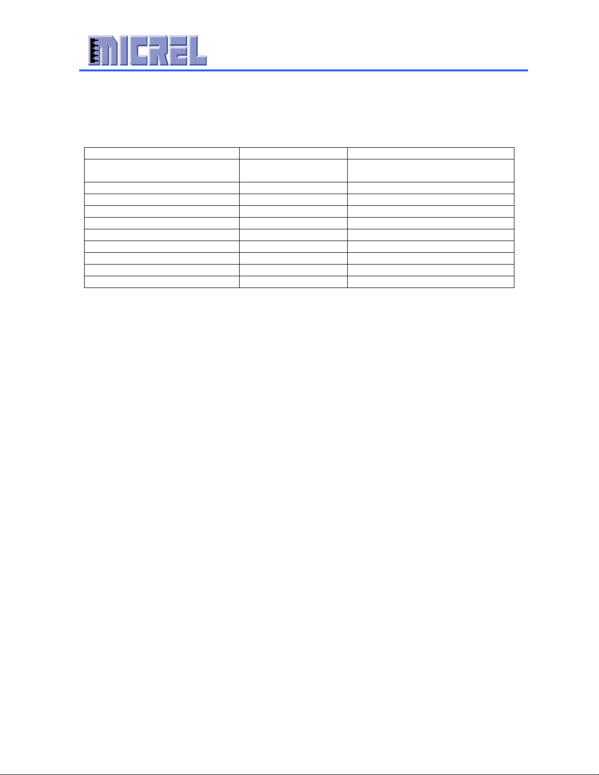
1.1 Revision History
Revision Date Description
1.0 9-26-03 Initial Release

Micrel Confidential 5
CENTAUR KS8695PX Demo Board Description
Integrated Multi-Port PCI Gateway Solutio
n
1.2 Introduction
The KS8695PX Demonstration Board is intended to provide a convenient means to
evaluate the functionality of the new KS8695PX Integrated Multi-Port PCI Gateway and
jump start software development. Micrel provides a complete Linux based SOHO Router
software solution with which to evaluate the KS8695PX functionality. The SOHO router
software includes a web based configuration utility to allow quick and easy device setup.
The demonstration board also has hardware support for a mini-PCI connector to address
the 802.11a/b/g wireless gateway router market, as well as a host of other applications
that take advantage of the multitude of devices that connect to PCI, miniPCI, or cardbus.
Packing List
The KS8695PX Evaluation Kit includes:
· 1 KS8695PX Demo Board
· 1 5.0 V, 4.0A DC power supply
· 1 Micrel Evaluation Kit CD
1.3 Hardware Features
· CENTAURäKS8695PX Integrated Multi-Port PCI Gateway Solution featuring
XceleRouteräTechnology
· 1 Mini-PCI connector
· 32 MB of SDRAM in 2 chips in a 4M x 32 bit configuration
· 4 MB of FLASH Memory, socketed for ease of development.
· 4 LAN 10/100 Ethernet Ports with 3 LED’s Per Port
· 1 WAN 10/100 Ethernet Port with 3 LEDs
· JTAG port for Multi-ICE connection
· UART DB-9 connector for hyperterminal connection
· Power LED

Micrel Confidential 6
CENTAUR KS8695PX Demo Board Description
Integrated Multi-Port PCI Gateway Solutio
n
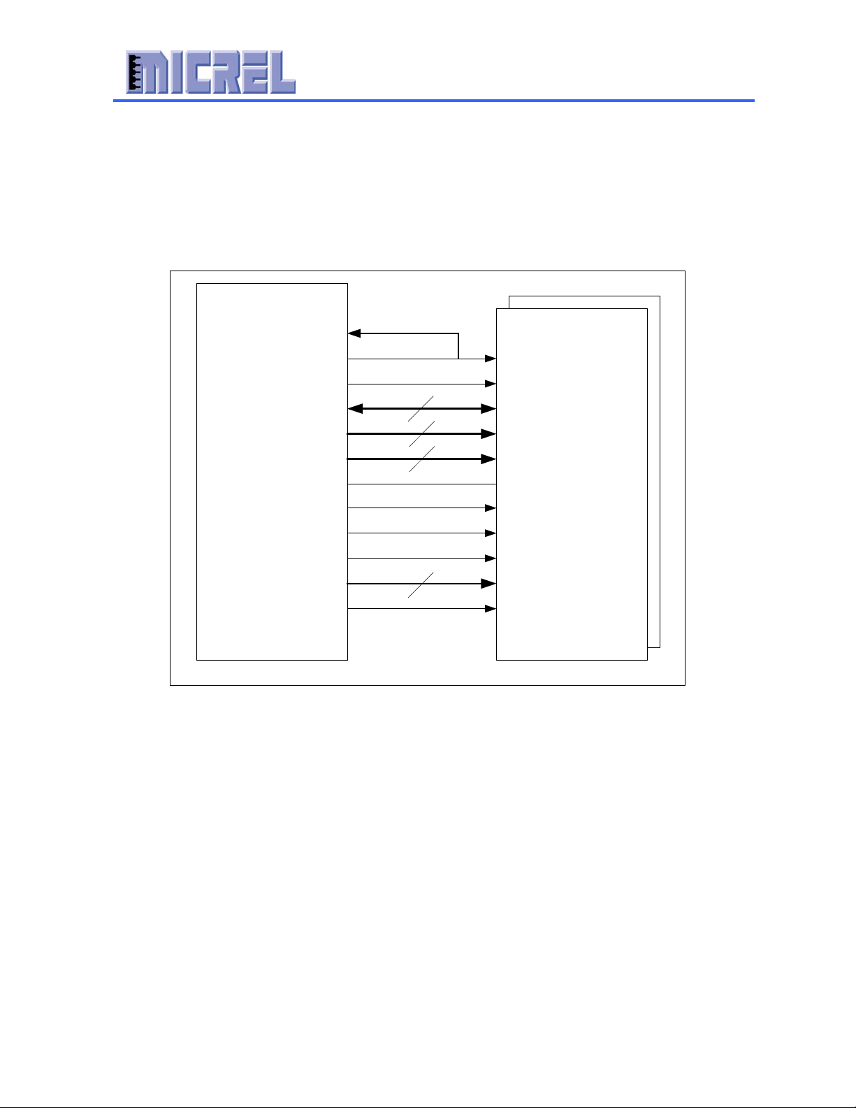
2.0 Functional Block Diagram
Figure 1 KS8695PX Demo Board Block Diagram
CENTAUR
GPIO Memory Bus
16 MB
STATUS LED
+1.8 V
MiniPCI0
16 MB
PCI BUS
4 MB
Et
he
rn
et LAN3
UART
LAN2
WAN
KS8695PX
SDRAM1
LAN1
JTAG/ICE
+3.3 V
LAN4
FLASH
5 V
Input
Reset
Power
SDRAM0
HOST MODE
TSOP Socket

Micrel Confidential 7
CENTAUR KS8695PX Demo Board Description
Integrated Multi-Port PCI Gateway Solutio
n
3.0 Getting Started
This section describes how to get the KS8695PX Reference Board up and running with
Micrel’s SOHO router software and your PC. You will need:
· Micrel KS8695PX Demo Board
· Micrel provided 5.0 V power supply.
· 1 Category 5 ethernet cable for the LAN, 1 Category 5 ethernet cable for the
WAN.
· 1 Null serial cable with female to female connectors for console port connection.
(Optional).
· 1 PC.
1. Connect the included 5.0 V power supply to the KS8695PX reference board and
plug it into a wall socket. When the board is plugged in, or when the reset button
on the board is depressed, you should see a flashing LED pattern. This is the
power on self-test (POST).
2. The ports on the KS8695PX board are labeled as WAN and LAN. Connect a PC
to one of the LAN ports and Internet service to the WAN port on the board.
Internet service can be replaced with a PC running a web server.
3. Connect a null serial cable (Optional) from the serial port of the KS8695PX
Reference Board to a PC to monitor Linux kernel boot time messages. After the
boot, a shell prompt is displayed for accepting Linux shell commands. For
instance, type the “ls” command to list the files of the current directory.
3.1 Configuring PC COM port settings
The Windows Hyper Terminal can be used as a console to communicate with the
KS8695PX Reference Board. The configuration settings for serial
communication are shown below.

Micrel Confidential 8
CENTAUR KS8695PX Demo Board Description
Integrated Multi-Port PCI Gateway Solutio
n
Figure 2 COM Port Configuration
4.0 Memory Map
Upon power up, the KS8695PX memory map is configured as shown below.
Table 1 Default Memory Map
Address Range Region Size Description
0x03FF0000-0x04000000 64 kbytes KS8695PX Configuration Register
Space
0x02000000-0x03FEFFFF 32Mbytes Not Configured
0x00000000-0x01FFFFFF 32Mbytes Flash Bank 0
Micrel Confidential 9
CENTAUR KS8695PX Demo Board Description
Integrated Multi-Port PCI Gateway Solutio
n
The default base address for the KS8695PX system configuration registers is 0x03ff0000.
After power up, the user is free to re-map the memory for his/her specific application.
Here is an example of the memory space remapped for operation:
Table 2 Memory Map Example
Address Range Region Size Description
0x03FF0000-0x04000000 64 kbyte KS8695PX Configuration Register
Space
0x03E00000-0x03FEFFFF 2 Mbyte Spare
0x03A00000-0x03DFFFFF 4 Mbyte External I/O bank 2
0x03600000-0x039FFFFF 4 Mbyte External I/O bank 1
0x03200000-0x0381FFFF 4 Mbyte External I/O bank 0
0x02800000-0x031FFFFF 10 Mbyte Space
0x01480000-0x027FFFFF 32 Mbyte FLASH Expansion Space
0x01400000-0x0147FFFF 500 kbyte FLASH
0x01000000-0x013FFFFF 4 Mbyte SDRAM Expansion Space
0x00000000-0x00FFFFFF 16 Mbyte SDRAM
Please see the KS8695PX Detailed Register Description document for more information.
4.1 KS8695PX
4.1.1 Board Reset
The KS8695PX reference board provides both a power on reset and a push button reset,
as well as circuitry to reset the board using the Multi-ICE. At power on, the board is
automatically reset. The user can also press S1, the reset button on the board for a
manual reset. After any reset, expect the LEDs to flash indicating the power on self test.
4.1.2 System Clock
The system clock is generated using a 25 MHz crystal (Y1). The crystal is connected to
the XCLK1 and XCLK2 inputs on the KS8695PX. The clock is specified as 3.3V
tolerant, +/- 100 ppm.
4.1.3 Jumpers
There are a number of jumpers and test points on the board to facilitate configuration and
testing of the KS8695PX. Below is a table that lists the jumpers and test points, their
purpose, and the recommended configuration on the board.

Micrel Confidential 10
CENTAUR KS8695PX Demo Board Description
Integrated Multi-Port PCI Gateway Solutio
n
Table 3 Configuration Jumpers
Configuration Jumper Description Recommended
Test1 JP3 No Connection for normal operation. No Connection
Test2 JP4 No Connection for normal operation. No Connection
M66EN JP9 PCI 66 MHz Enable. (Not available
on this board.)
‘0’ 33 MHz for
this board to
operate
GPIO[11:6] JP5 GPIO test points for testing
No connection
4.1.4 Chip Select Assignments
Table 4 Chip Select Assignments
KS8695PX Chip Select
Signal
KS8695PX Pin # Device
SDCSN0 P5 SDRAM Bank 0
SDCSN1 R4 SDRAM Bank 1
RCSN0 P15 FLASH
RCSN1 R15 Not assigned
ECSN0 R16 Not assigned
ECSN1 T16 Not assigned
ECSN2 U16 Not assigned
Micrel Confidential 11
CENTAUR KS8695PX Demo Board Description
Integrated Multi-Port PCI Gateway Solutio
n
4.1.5 SDRAM
The KS8695PX reference board supports 32 MB of SDRAM with 2 chips in a 4Mx32 bit
configuration. The KS8695PX provides a glueless interface to the SDRAM as shown in
Figure 2. The SDRAM interface can also be programmed to support 16 bit SDRAM.
Figure 3 KS8695PX SDRAM Interface
SDOCLK
SDCKE
DATA[31..0]
ADDR[10..0]
SDRASN
SDCASN
SDQM[3..0]
SDWEN
KS8695P
SDRAM
4M x 32
CLK
CKE
CS#
WE#
CAS#
RAS#
A[10..0]
DQ[31..0]
SDCSN1
SDCSN0
DQM[3..0]
ADDR[21..20] BA[1..0]
32
11
2
4
SDICLK
Micrel Confidential 12
CENTAUR KS8695PX Demo Board Description
Integrated Multi-Port PCI Gateway Solutio
n
Table 5 KS8695PX SDRAM Signals
KS8695 Signal SDRAM Signal Description
SDOCLK CLK Clock from KS8695PX to
SDRAM.
SDICLK N/A (Feedback from
SDOCLK)
KS8695PX uses this clock to
register SDRAM data.
DATA[31..0] DQ[31..0] Bi-directional data bus
ADDR[11..0] A[11..0] Address bus
ADDR[21..20] BA[1..0] Bank Address Inputs
SDCSN0 CS# (Chip 0) SDRAM chip select (active low)
SDCSN1 CS# (Chip1) SDRAM chip select (active low)
SDRASN RAS# SDRAM row address strobe
(active low)
SDCASN CAS# SDRAM column address strobe
(active low)
SDQM[3..0] DQM[3..0] SDRAM input/output mask.
SDWEN WE# SDRAM write enable

Micrel Confidential 13
CENTAUR KS8695PX Demo Board Description
Integrated Multi-Port PCI Gateway Solutio
n
4.2 Flash
The KS8695PX provides a glueless interface to flash memory as shown in Figure 4. The
KS8695PX Demo Board supports 1 flash memory chip either in a socket or mounted
directly. The socketed chip makes for easier development. The layout supports either a
2Mx8 or 4Mx8 bit flash chip. The flash memory occupies external static memory bank
0. The KS8695PX flash data bus width is programmable for 8, 16, or 32 bits. The
system addressing is determined by the WLED[1:0]/B0SIZE[1:0] inputs. The
KS8695PX will automatically adjust the system addressing for byte wide, half word wide
(16 bit), or word wide (32 bit) flash configurations. B0SIZE[1:0] is hard coded to “01”
for 8 bit flash on the KS8695PX Demo Board.
Figure 4 KS8695PX Flash Interface
DATA[31..0]
ADDR[20..0]
RCSN0
B0SIZE[1..0]
KS8695P
EROEN
ERWEN0
32
2
FLASH(U3)
2M x 8 or
4M x8
WE#
CE#
A[20..0]
DQ[7..0]
OE#
RESET# RY/BY#
WRSTO
21
DATA[7..0]
ADDR[20..0]
ERWEN1
ERWEN2
ERWEN3
B0SIZE[1:0]
"01" = 8 bits
"10" = 16 bits
"11" = 32 bits
Micrel Confidential 14
CENTAUR KS8695PX Demo Board Description
Integrated Multi-Port PCI Gateway Solutio
n
4.3 Mini-PCI Interface
The KS8695PX Reference Board provides one miniPCI socket to allow testing of 802.11
g/b/a combo gateway applications, as well as a multitude of other miniPCI applications.
In total, the KS8695PX can support 3 external PCI masters, and provides a glueless
interface for Cardbus and standard PCI as well as miniPCI. The KS8695PX PCI
interface supports 33 MHz and is compliant with PCI Local Bus Specification 2.1. The
KS8695PX Demo Board miniPCI interface is shown below.
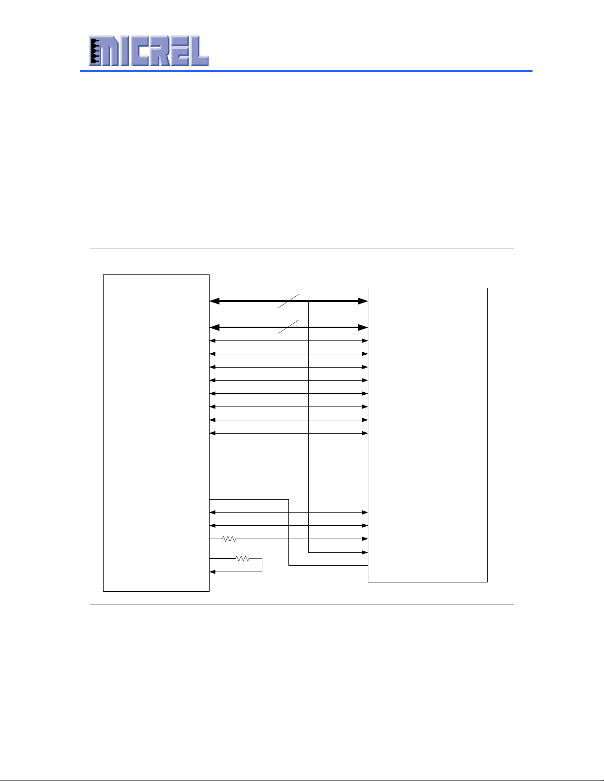
Figure 5 KS8695PX MiniPCI Interface
KS8695P
32
4
PAD[31:0]
CBEN[3:0]
PAR
FRAMEN
TRDYN
IRDYN
STOPN
DEVSELN
SERRN
PERRN
REQ1N
GNT1N
PCLKOUT1
AD[31:0]
C/BE[3:0]#
PAR
MiniPCI 0
PCLKOUT0
PCLK
IDSEL
FRAME#
TRDY#
IRDY#
STOP#
DEVSEL#
SERR#
PERR#
REQ#
GNT#
CLK
PAD[16]
GPIO0/INT0
INTA
The miniPCI interface on the reference board supports only 3.3V cards, but power is
provided to the 5.0V pins on the miniPCI connector. There are two general purpose
LED’s provided on pins 11 and 12 of the connector.
The KS8695PX will work with most wireless LAN chipset provider miniPCI solutions.
Micrel Confidential 15
CENTAUR KS8695PX Demo Board Description
Integrated Multi-Port PCI Gateway Solutio
n
4.4 External Interfaces
4.4.1 WAN Interface
The WAN interface on the KS8695PX is connected to a single transformer with a 50 ohm
differential termination on the transmit side. The line side of the transformer will be
connected to pins 3 (TX+) and 6 (TX-) on the RJ-45 connector. With additional
circuitry, the WAN interface can also support 100 Base FX and interface with fiber optic
modules.
4.4.2 LAN Interfaces
The LAN interfaces on the KS8695PX are connected to a quad transformer with a 50
ohm differential termination on the transmit side for each port. The line side of the
transformer is connected to pins 3 (TX+) and 6 (TX-) on the RJ-45 connectors for LAN
ports 1-4. With additional circuitry, the LAN1 interface can also support 100 Base FX
and interface with fiber optic modules.
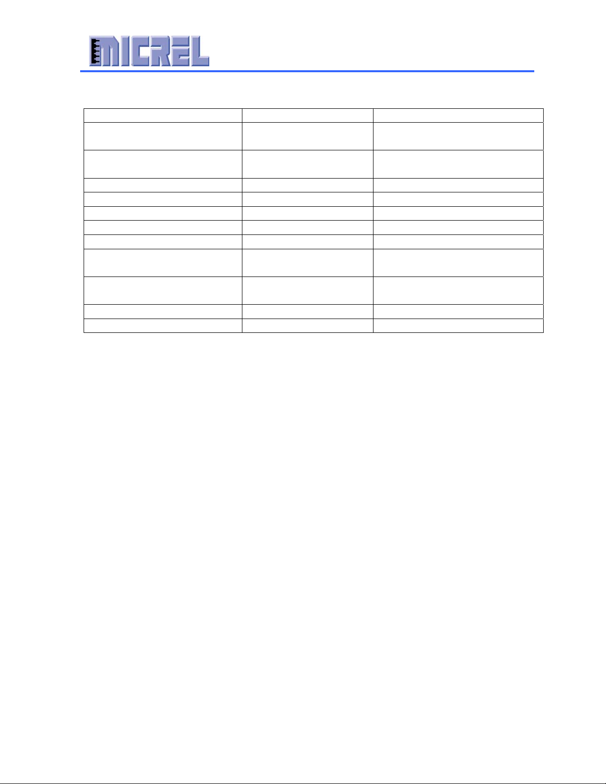
4.4.3 UART
The KS8695PX provides a high speed UART interface. The UART supports up to 120
kbps. The UART interface is a male DB9 connector used for dial-up back up or a
console port.
Connector
Pin No.
KS8695PX Signal Name KS8695PX
I/O
KS8695PX Signal Description
1 UDCDN I UART Data Carrier Detect
2 URXD I UART Receive Data
3 UTXD O UART Transmit Data
4 UDTRN O Data Terminal Ready (active low)
5 N/A N/A Ground
6 UDSRN I UART Data Set Ready
7 URTSN O UART Request To Send
8 UCTSN I Clear To Send
9 URIN I Ring Indicator

Micrel Confidential 16
CENTAUR KS8695PX Demo Board Description
Integrated Multi-Port PCI Gateway Solutio
n
4.4.4 Multi-ICE/JTAG Connector
The KS8695PX JTAG interface (JP4) is a standard 20 pin connector for the Multi-ICE.
This connector can be used to download code to flash, and for software development and
debugging purposes.
Pin No. Signal
1 3.3V
2 3.3V
3 NTRST
4 GND
5 TDI
6 GND
7 TMS
8 GND
9 TCK
10 GND
11 RTCK
12 GND
13 TDO
14 GND
15 SRST
16 GND
17 DBGRQ
18 GND
19 DBGACK
20 GND
The DBGRQ and DBACK signals are not be supported on the KS8695PX Demo Board.
4.4.5 LEDs
The KS8695PX provides 2 LED’s per LAN or WAN port. These LED indicators are
fully programmable. The KS8695PX Demo Board also offers a 3rd LED per port using
GPIO pins. The GPIO pins can be programmed as LED indicators with the proper
software. Please see the KS8695PX Register Description for more information on
programming the LED indicators. The KS8695PX Demo Board features a power LED so
that the user may easily determine if the board is on.
1. Power LED (D9)
2. WAN LEDs (D4)
3. LAN Port 1 LEDs (D5)
4. LAN Port 2 LEDs (D6)
5. LAN Port 3 LEDs (D7)
6. LAN Port 4 LEDs (D8)

Micrel Confidential 17
CENTAUR KS8695PX Demo Board Description
Integrated Multi-Port PCI Gateway Solutio
n
4.4.6 GPIO
The KS8695PX features 16 general purpose I/O pins (GPIO). These pins can be use for
external controls, or inputs for use by the KS8695PX. For example, GPIO[7:3] are used
to add a 3rd LED per port. GPIO[11:8] are connected to JP5 and can be used to emulate
an SPI interface for peripheral components.
4.5 Power and Ground
Voltage to the Demo Board is supplied through a 5.0 V DC power jack. The dc power is
then translated down to the voltage levels required with Micrel voltage regulators. These
voltage regulators were chosen for stability in evaluation and testing. A mass production
design can use low cost voltage regulators to supply the KS8695PX. The KS8695PX has
the option to use a switching regulator (MIC2193, U10), or an LDO regulator
(MIC29300-3.3BT, U11). Note that both the switching regulator and the LDO should not
be populated on the board at the same time.
Table 6 Voltage Test Points
Voltages Test Points
V1.8A (Analog RX) TP1
V1.8 (Digital Core) TP2
V3.3A (Analog TX) TP3
V3.3D (KS8695PX digital I/O) TP4
GND TP5, TP6, TP7, TP8
This manual suits for next models
1
Table of contents
Popular Gateway manuals by other brands


 user guide")


CONTROL SOLUTIONS
CONTROL SOLUTIONS Babel Buster Pro V210 quick start guide

Honeywell
Honeywell NOTIFIER NFN-GW-PC-HNMF Installation and operation manual

MOKO
MOKO MK105 user manual

RTA
RTA 460PSSC-N34 Product user guide

NavCom Technology
NavCom Technology REX-Bluetooth user manual

Cree
Cree SmartCast Wireless Gateway installation instructions


