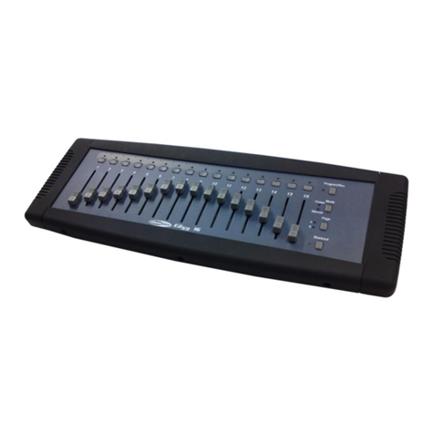
Micro-Comm S4500 Assembly instructions

Micro-Comm RTU32 PLC
User’s Reference Manual
(S4500, M1500, M550, M555, M1550, M1650, M655, M1600)
Revised: July 22, 2019
Copyright © 2019 Micro-Comm, Inc.

Table of Contents
S4500 PLC .................................................................................................................................................................. 3
S4500 Specications and Sales Information ........................................................................................................ 4
M1500 PLC ................................................................................................................................................................. 6
M1500 Specications and Sales Information ....................................................................................................... 7
M550 PLC ................................................................................................................................................................... 9
M550 Specications and Sales Information ....................................................................................................... 10
M555 PLC ................................................................................................................................................................. 11
M555 Specications and Sales Information ....................................................................................................... 12
M555 Installation Requirements ......................................................................................................................... 14
M555 Lithium Battery Replacement ................................................................................................................... 15
M1550 PLC ............................................................................................................................................................... 16
M1550 Specications and Sales Information ..................................................................................................... 17
M1550 Installation Requirements ....................................................................................................................... 19
M1550 Lithium Battery Replacement ................................................................................................................. 20
M1650, M655 and M1600 PLC ................................................................................................................................. 21
M1650 Specications and Sales Information ..................................................................................................... 22
M655 Specications and Sales Information ....................................................................................................... 24
M1600 Specications and Sales Information ..................................................................................................... 26
Expansion I/O Module Setup .................................................................................................................................... 28
Communication Port Pinouts .................................................................................................................................... 29
Display Module Operation......................................................................................................................................... 30
RTU32 Protocol I/O Mapping.................................................................................................................................... 31
Allen-Bradley DF1 and Modbus Protocol Support.................................................................................................... 33
Allen-Bradley Ethernet/IP and Modbus/TCP Protocol Support................................................................................ 34
RTU Conguration 32................................................................................................................................................ 35
RTU Information Screen ..................................................................................................................................... 36
Conguration Parameters................................................................................................................................... 37
Analog Labels and Scaling Factors .................................................................................................................... 41
Output Timer Labels ........................................................................................................................................... 42
Stop/Start Setpoint Labels ................................................................................................................................. 43
X Variable Labels................................................................................................................................................. 44
Discrete I/O Labels ............................................................................................................................................. 45
User Memory Screens ........................................................................................................................................ 46
User Memory Table ............................................................................................................................................. 47
RTU Script Language Editor ............................................................................................................................... 48
Commented Script / Revision Editor .................................................................................................................. 49
Data Table Viewer ............................................................................................................................................... 50
Display Module Emulator.................................................................................................................................... 51
Debug Terminal ................................................................................................................................................... 52

- 3 -
S4500 PLC
The S4500 is a fourth-generation Micro-Comm RTU/PLC built on the S4000 motherboard
utilizing a new daughterboard with a faster 32bit microprocessor and more RAM and FLASH
memory. As a result, the S4500 software has the following enhanced features:
I/O capabilities:
(8) Relay outputs with conrmation read-back inputs
(8) Open-collector outputs
(16) Discrete inputs (contact closure) / low speed pulse inputs (up to 50Hz)
(8) 12-bit analog inputs (0-20mA or 0-5volt dip switch selectable)
(8) additional 12-bit analog inputs
(4) 0-5volt analogs AI9-AI12 on the terminal blocks
(4) internal signals: RTU temperature (0.25 to 4.75v = -50C to +150C = -58F to +302F),
Battery Voltage (0 to 5v = 0 to 25.5 volts from battery),
Battery Current (0 to 5v = -10 to +10 amps from battery) plus an input on COM1 25pin port
(2) Pulse inputs - high speed (2.5kHz/500Hz)
(2) RS-232 communication ports
- COM1 is the radio (COM1B=9pin monitor port, COM1A=25pin for radio cable)
- COM2 is a 9pin port normally used for the display module and programming
(1) RS-485 communication port
- COM3 is a 4-wire RS-485 port for I/O modules or for PLC communication
(12) Address input switches
Changes and Enhanced Features:
• Setup requires the newer “RTU Conguration 32” program
• New data table and user memory viewing options in RTU Conguration 32
• New Micro-Comm RTU32 protocol
• New personality module required with 1MB of serial ash (yellow label)
• User Memory is now 9000 words of non-volatile RAM
• User NV Memory is now 65000 words of personality module FLASH
• User Memory screens added to Micro-Comm display module for custom variables/parameters
• Much larger communication buers for relaying and programming
• Additional protocols on all COM ports (DF1 Half-Duplex Master, DF1 Full-Duplex, Modbus/TCP etc.)
• Modbus and DF1 Half-Duplex Store & Forward (SFTABLE function) on COM1
• PID for up to 16 analog outputs can now all be running at the same time
• Increased maximum script and subroutine size (16KB for main, 2KB for each subroutine)
• Added more subroutines SUB5()-SUB20() and increased # of parameters to 16 (L1-L16)
• Additional pulse inputs (50Hz max) using DI1-DI16 are now available - PI3-PI18
• New script variables for runtimes and cycle counts for DI1-DI16 and DO1-DO8
• Added the RESPOND() script function that can dene up to 128 more addresses
• Added the LISTEN() script function that can listen to up to 128 other RTU replies and save the data
• New script functions: TOTALIZE(),MCOPY(),MFILL(),MAVG(),OSR(),PITOAI(), XCOPY()
• SCALE() function no longer changes the given variable, it just returns the scaled value
• New script variables M0-M8999 to make access to user memory locations much easier
• Added the GROUP() and CGLEVEL() functions to dene and automate control groups for SCADAview 32
• New CTU32 protocol option on COM2 and COM3 for use with SCADAview 32
• Added COM2 baud rate and PTT time options for data radio support
• DF1 Radio Modem protocol for all COM ports along with Store & Forward option on COM1
• Revision notes / commented script can now be stored in the personality module (up to 64K bytes)
• A compressed PC le can now be stored in the personality module (up to 256K bytes)

- 4 -
S4500 Specications and Sales Information
PROGRAMMABLE LOGIC CONTROLLER
(PLC)
FULLY PROGRAMMABLE WITH
PLUG-IN MEMORY MODULE
MICRO-COMM RTU, MODBUS
RTU & ALLEN-BRADLEY DF1
PROTOCOLS
OPTIONAL FRONT PANEL
DISPLAY & EXPANDABLE I/O
RADIO, PHONE LINE, & FIBER
OPTIC COMMUNICATIONS
SIMULTANEOUS RTU-RTU &
CTU-RTU COMMUNICATIONS
PLUG-IN TERMINAL BLOCKS
The S4500 PLC is a reliable, full-fea-
tured Progammable Logic Controller.
It is a “smart” unit providing both
programmability and interchange-
ability through a plug-in memory module. As
an integrated component of a Supervisory
Control and Data Acquisition System (SCADA),
the S4500 provides input and output (I/O)
monitoring and control with simultaneous
“distributed” (RTU to RTU) and “central” (CTU
to RTU) type control operations. Its universal
communications interface can provide robust
control and data transfer via radio, dedicated
line, phone line, and fiber optic communication
media.
APPLICATIONS
SCADA Systems:
Water Distribution Control and Management
Waste Water Control and Monitoring
Golf Course Irrigation
Agricultural Irrigation
Gas and Oil Monitoring
Electrical Distribution Monitoring
Local Control:
Water Booster Pump Stations
Sewage Lift Stations
Constant and Variable Speed Pump Stations
Metering Stations
Water and Waste Water Treatment Plants
MODEL S4500
FEATURES
I/O
• 8 Form C Relay Outputs,
• 8 Open Collector Outputs,
• 16 Optically Isolated Discrete Inputs,
• 2 Optically Isolated High Speed Pulse Input,
• 1 Pulse Amplification Circuit for Direct
Connection to Flow Meter
• 12 Analog Inputs, 0-5V or 0-20mA
• 4 Additional On-Board Sensor Analog Inputs
Box Temperature, Battery Current,
System Voltage, Receive Signal Strength
Communications
• COM-1A, Radio Port
25pin Sub-D Male, RS-232 and RF signals
• COM-2, Front Panel Display
9pin Sub-D Male RS-232 w/flow control
lines
• COM-3, RS-485
• Plug In RF MODEM
0-300, 600, 1200 BAUD
Power Source and Supplies
• 120/240 VAC Power Input Isolation trans-
former
• SOLAR charging circuit
• Battery charging and backup circuit
• 13.8VDC @ 8A Switching Power supply
• 12 to 24VDC @ 200mA
Sensor Excitation power supply
Micro-Comm Automation has
been providing process control solutions
for more than 30 years.
Call us at (913) 390-4500 to place
your order or to speak to a sales and ser-
vice representative. Or, visit us online at
www.micro-comm-inc.com

- 5 -
i/o
• 8 Form C Relay Outputs, 5A @ 250VAC
• 8 Open Collector Outputs, 100mA @ 12VDC
• 16 Optically Isolated Discrete Inputs, Dry
Contact or Pulse Inputs
• 2 Optically Isolated High Speed Pulse Inputs
• 1 Pulse Amplification Circuit for Direct
Connection to Flow Meter
• 12 Analog Inputs
8ch, 12bit, 0-5V or 0-20mA
4ch, 12bit, 0-5V
• 1 Analog Amplifier Circuit
• 4 Additional On-Board Sensor Analog Inputs
Box Temperature, -50 to 150°C
Battery Current, ±10A
System Voltage
Receive Signal Strength
Power source and suPPlies
• 120/240 VAC Power Input isolation
transformer and surge suppression
• SOLAR charging circuit
• Battery charging and backup circuit
• 13.8VDC @ 8A Switching Power supply
• 12 to 24VDC @ 200mA
Sensor Excitation power supply
cPu and memory
• 32bit MCU running @ 16MHz
• 1MB FLASH EPROM, Application Program
• 512K RAM, Data
• 1MB Serial FLASH, Configuration
communications
• COM-1A, Radio Port
25pin Sub-D Male, RS-232 and RF signals
• COM-1B, Radio Monitor Port
9pin Sub-D Male TxD, RxD, RTS, GND
• COM-2, Front Panel Display
9pin Sub-D Male RS-232 w/flow control lines
• COM-3, RS-485, 1200–9600 BAUD remote I/O
• Plug In RF MODEM
0-300, 600, 1200 BAUD
order information
L15F-xxxx
Modem:
0 - none (110-19200 baud RS-232)
L17 - 0-300 baud radio modem
L17A - 0-600 baud radio modem
Micro-Comm, Inc. • 15895 S Pflumm Rd • Olathe, KS 66062 • (913) 390-4500 • fax: (913) 390-4550 • www.micro-comm-inc.com
s4500 Plc
L15F-L17A

- 6 -
M1500 PLC
The M1500 is a fourth-generation Micro-Comm controller built with the processor daughterboard
from the S4500 (32bit microprocessor). The M1500 is physically much smaller than the S4500,
having the reduced I/O count listed below:
I/O capabilities:
(4) Relay outputs
(4) Open-collector outputs (COM1 pins used for radio switching)
(8) Discrete inputs (contact closure), (2) high speed pulse, (6) low speed pulse
(4) Analog Inputs (12bit, 0-20mA or 0-5volt dip switch selectable)
(2) additional 12bit analog inputs
Temperature (0.25 to 4.75v = -50C to +150C = -58F to +302F),
System Voltage (0 to 5v = 0 to 25.5 volts)
(2) Analog Outputs (0-20mA)
(2) RS-232 communication ports
- COM1 25pin port for radio cable
- COM2 9pin port normally used for the display module and programming
(1) RS-485 communication port
- COM3 is a 4-wire RS-485 port for I/O modules or for PLC communication

- 7 -
M1500 Specications and Sales Information
FULLY PROGRAMMABLE WITH
PLUG-IN MEMORY MODULE
MICRO-COMM, MODBUS RTU
AND ALLEN-BRADLEY DF1
PROTOCOLS
OPTIONAL FRONT PANEL
DISPLAY & EXPANDABLE I/O
RADIO, PHONE LINE, & FIBER
OPTIC COMMUNICATIONS
SIMULTANEOUS RTU-RTU &
CTU-RTU COMMUNICATIONS
PLUG-IN TERMINAL BLOCKS
MODEL M1500
The M1500 PLC is a reliable, full-
featured Programmable Logic
Controller. It is a “smart” unit
providing both programmability and
interchangeability through a plug-in memory
module. As an integrated component of a
Supervisory Control and Data Acquisition System
(SCADA), the M1500 provides input and output
(I/O) monitoring and control with simultaneous
“distributed” (RTU to RTU) and “central” (CTU
to RTU) type control operations. Its universal
communications interface can provide robust
control and data transfer via radio, dedicated
line, phone line, and fiber optic communication
media.
APPLICATIONS
SCADA Systems:
Water Distribution Control and Management
Waste Water Control and Monitoring
Golf Course Irrigation
Agricultural Irrigation
Gas and Oil Monitoring
Electrical Distribution Monitoring
Local Control:
Water Booster Pump Stations
Sewage Lift Stations
Constant and Variable Speed Pump Stations
Metering Stations
Water and Waste Water Treatment Plants
FEATURES
I/O
• 4 Form C Relay Outputs
• 4 Open Collector Outputs
• 8 Optically Isolated Discrete Inputs
(2 are also High Speed Pulse Inputs)
• 4 Analog Inputs, 0-5V or 0-20mA
• 2 Additional On-Board Sensor Analog Inputs
Box Temperature, System Voltage
• 2 Analog Outputs, 0-20mA
Communications
• COM1, Radio Port
25pin Sub-D Male, RS-232 and RF signals
• COM2, Front Panel Display, Programming
9pin Sub-D Male RS-232 w/flow control
lines for optional 2nd data radio
• COM3, RS-485, Expansion I/O
• Plug In RF MODEM
0-300, 600, 1200 BAUD
Power Source and Supplies
• 12 VDC Power Input
• 24VDC @ 200mA
Sensor Excitation power supply
Micro-Comm Automation has
been providing process control solutions
for more than 30 years.
Call us at (913) 390-4500 to place
your order or to speak to a sales and ser-
vice representative. Or, visit us online at
www.micro-comm-inc.com
PROGRAMMABLE LOGICCONTROLLER
(PLC)

- 8 -
order information:
L51-xxxx
Modem:
0 - none (110-19200 baud RS-232)
L17 - 0-300 baud radio modem
L17A - 0-600 baud radio modem
L17B - 1200 baud radio modem
Micro-Comm, Inc. • 15895 S Pflumm Rd • Olathe, KS 66062 • (913) 390-4500 • fax: (913) 390-4550 • www.micro-comm-inc.com
m1500 plC
i/o
• 4 Form C Relay Outputs, 10A @ 250VAC (10A @ 30VDC Resistive)
Relay contact to coil isolation 4000Vrms
• 4 Open Collector Outputs, 100mA @ 12VDC (COM1 pins)
• 8 Optically Isolated Discrete Inputs, Dry Contact or Pulse Inputs
Discrete Input optical isolation 5300Vrms
2 High Speed Pulse Inputs (discrete inputs 7 and 8)
0-1kHz, 50% duty cycle, contact closure or
open collector to GND
6 Low Speed pulse inputs (discrete inputs 1-6)
0-50Hz, 50% duty cycle, contact closure or
open collector to GND
• 4 Analog Inputs, 12bit, 0-5V or 0-20mA, 0.1% accuracy,
0.001%/degC temp. coefficient, +/- 24V over voltage
• 2 Additional On-Board Sensor Analog Inputs
Box Temperature, 0-150°F
System Voltage, 0-25.5V
• 2 Analog Outputs, 0-20mA, 2.5% accuracy
900 ohm maximum loop resistance
power sourCe and supplies
• 10.5-15 VDC Power Input, 10A
• 24VDC @ 100mA each output, 200mA total
Sensor Excitation power supply
• COM1 (pins 9,10,20) 4A
• COM2 (pin 4) 2.5A
• COM3 (12V) 2.5A
Cpu and memory
• 32-bit MCU running 16MHz
• 1MB FLASH, Application Program
• 512K RAM, Data
• 1MB Serial FLASH, Configuration
CommuniCations
• COM1, Radio Port
DB25M, RS-232 and RF signals
• COM2, Front Panel Display, Programming
DB9M RS-232 w/flow control lines
• COM3, RS-485 4 wire, 110–19200 BAUD
• Plug In RF MODEM
FSK 0-300, 600, 1200 BAUD
dimensions
• Height 9.75”
• Width 6.85”
• Depth 3.35” (with personality module)
• Weight 2.3 lb

- 9 -
M550 PLC
The M550 is a fourth-generation Micro-Comm controller built with the processor daughterboard
from the S4500 (32bit microprocessor). The M550E is a version of the M550 with an Ethernet
port in place of the COM2 serial port.
The M550 is physically much smaller than the S4500, having the reduced I/O count listed
below:
I/O capabilities:
(4) Open-collector outputs (COM1 pins used for radio switching)
(2) On-board 12bit analog inputs
Temperature (0.25 to 4.75v = -50C to +150C = -58F to +302F),
System Voltage (0 to 5v = 0 to 25.5 volts)
(3) Communication ports
- COM1 25pin port for radio cable
- COM2 9pin port used for the display module and programming
(Note: The M550E has an Ethernet 10baseT port for COM2)
- COM3 can be congured as an RS-485 port for I/O modules or as an RS-232 port with PTT supprt

- 10 -
M550 Specications and Sales Information
FULLY PROGRAMMABLE WITH PLUG-IN
MEMORY MODULE
MICRO-COMM, MODBUS RTU AND
ALLEN-BRADLEY DF1 PROTOCOLS
OPTIONAL FRONT PANEL DISPLAY &
EXPANDABLE I/O
RADIO, PHONE LINE, & FIBER OPTIC
COMMUNICATIONS
SIMULTANEOUS RTU-RTU & CTU-RTU
COMMUNICATIONS
MODEL M550
The M550 PLC is a reliable, full-
featured Programmable Logic
Controller. It is a “smart” unit
providing both programmability and
interchangeability through a plug-in memory
module. As an integrated component of a
Supervisory Control and Data Acquisition System
(SCADA), the M550 provides input and output
(I/O) monitoring and control with simultaneous
“distributed” (RTU to RTU) and “central” (CTU
to RTU) type control operations. Its universal
communications interface can provide robust
control and data transfer via radio, dedicated
line, phone line, and fiber optic communication
media. The M550 can also be ordered with an
Ethernet controller in place of the RS-232 on
COM2 (Model M550E).
APPLICATIONS
Water Distribution Control and Management
Waste Water Control and Monitoring
Golf Course Irrigation
Agricultural Irrigation
Gas and Oil Monitoring
Electrical Distribution Monitoring
FEATURES
I/O
• 4 Open Collector Outputs (COM1 radio
switching)
Communications
• COM1, Radio Port
25pin Sub-D Male, RS-232 and RF signals
• COM2, Front Panel Display, Programming
9pin Sub-D Male RS-232 w/flow control
lines for data radio or Ethernet (10baseT)
• COM3, RS-485 Expansion I/O or RS-232
w/flow control lines for data radio
• Internal RF MODEM, 0-600 BAUD
CPU and Memory
• 32-bit MCU running 16MHz
• 1MB FLASH, Application Program
• 512K RAM, Data
• 1MB Serial FLASH, Configuration
Power Source
• 12 VDC Power Input
ORDER INFORMATION
Part #
L52 0-300 baud FSK modem, COM2 RS-232
L52A 600 baud FSK modem, COM2 RS-232
L52E 0-300 baud FSK modem, COM2 Ethernet
L52AE 600 baud FSK Modem, COM2 Ethernet
Micro-Comm Automation has
been providing process control solutions
for more than 30 years.
Call us at (913) 390-4500 to place
your order or to speak to a sales and ser-
vice representative. Or, visit us online at
www.micro-comm-inc.com
Micro-Comm, Inc. • 15895 S Pflumm Rd • Olathe, KS 66062 • (913) 390-4500 • fax: (913) 390-4550 • www.micro-comm-inc.com
PROGRAMMABLE LOGICCONTROLLER
(PLC)

- 11 -
M555 PLC
The M555 is a fth-generation Micro-Comm controller similar to the M550E PLC, but with a
faster processor, more memory, faster ethernet port and 2 additional communication ports.
I/O capabilities:
(4) Open-collector outputs (COM1 pins used for radio switching)
(2) On-board 12bit analog inputs
Temperature (0.25 to 4.75v = -50C to +150C = -58F to +302F),
System Voltage (0 to 5v = 0 to 25.5 volts)
(3) Communication ports
- COM1 25pin port for radio cable
- COM2 9pin port used for the display module and programming
- COM3 9pin can be congured as an RS-485 port for I/O modules or as an RS-232 port with PTT supprt
- COM4 9pin can be congured as RS-485/RS-232
- COM5 is an Ethernet 100baseT (RJ-45) port

- 12 -
M555 Specications and Sales Information
FULLY PROGRAMMABLE WITH PLUG-IN
MEMORY MODULE
MICRO-COMM, MODBUS RTU AND
ALLEN-BRADLEY DF1 PROTOCOLS
OPTIONAL FRONT PANEL DISPLAY &
EXPANDABLE I/O
RADIO, PHONE LINE, ETHERNET & FIBER
OPTIC COMMUNICATIONS
SIMULTANEOUS RTU-RTU & CTU-RTU
COMMUNICATIONS
MODEL M555
The M555 PLC is a reliable, full-
featured Programmable Logic
Controller. It is a “smart” unit
providing both programmability and
interchangeability through a plug-in memory
module. As an integrated component of a
Supervisory Control and Data Acquisition System
(SCADA), the M555 provides input and output
(I/O) monitoring and control with simultaneous
“distributed” (RTU to RTU) and “central” (CTU
to RTU) type control operations. Its universal
communications interface can provide robust
control and data transfer via radio, dedicated
line, phone line, and fiber optic communication
media.
APPLICATIONS
Water Distribution Control and Management
Waste Water Control and Monitoring
Golf Course Irrigation
Agricultural Irrigation
Gas and Oil Monitoring
Electrical Distribution Monitoring
FEATURES
I/O
• 4 Open Collector Outputs (COM1 radio
switching)
Communications
• COM1, Radio Port,
25pin Sub-D Male, RS-232 and RF signals
• COM2, RS-232, 9pin Sub-D Male
• COM3, RS-485 / RS-232, 9pin Sub-D Male
• COM4, RS-485 / RS-232, 9pin Sub-D Male
• COM5, Ethernet 100baseT
• Internal RF MODEM, 0-600 BAUD
CPU and Memory
• 32-bit MCU running 25MHz
• 1MB FLASH, Application Program
• 1MB RAM, Data
• 9MB Serial FLASH, Configuration
Power Source
• 12 VDC Power Input
ORDER INFORMATION
Part #
L55 0-300 baud FSK modem
L55A 600 baud FSK modem
Micro-Comm Automation has
been providing process control solutions
for more than 30 years.
Call us at (913) 390-4500 to place your
order or to speak to a sales and service
representative. Or, visit us online at www.
micro-comm-inc.com
PROGRAMMABLE LOGICCONTROLLER
(PLC)

- 13 -
order information:
L55x
Modem:
L55 - 0-300 baud FSK modem
L55A - 0-600 baud FSK modem
L55B - 1200 baud FSK modem
Micro-Comm, Inc. • 15895 S Pflumm Rd • Olathe, KS 66062 • (913) 390-4500 • fax: (913) 390-4550 • www.micro-comm-inc.com
m555 plC
i/o
• 4 Open Collector Outputs, 100mA @ 12VDC (COM1 pins)
Internal clamping diode to 12V, Used only for antenna switching, not
field wire-able
• 2 On-Board Sensor Analog Inputs, 12bit, 0.1% accuracy
Box Temperature, 0-150°F
System Voltage, 0-25.5V
power sourCe and supplies
• Power Supply 12VDC Isolated Source with 8A Fuse,
Use 14AWG Supply Connections
• Power Input 10.5-15 VDC, 12VDC Nominal, 8.0A
• Quiescent Current 85mA
• COM1 (pins 9,10,11) 10.5-15VDC, 4.0A, Self Resetting Fuse
• COM2 (pin 4) 10.5-15VDC, 2.0A, Self Resetting Fuse
• COM3 (pin 4) 10.5-15VDC, 2.0A, Self Resetting Fuse
• COM4 (pin 4) 10.5-15VDC, 2.0A, Self Resetting Fuse
• The sum of the load currents must be 7.5A or less
• Temperature Range -40 to 50 degC (-40 to 122 degF)
Surrounding Air Temperature
• Internal Battery Lithium 3V, 1200mAh, 2/3A Size
(Real-Time Clock and NVRAM)
• Field Wiring - Use Copper Conductors Only, 60°C
Wire Range, 12-26 AWG
Wire Strip Length, 0.310”
Recommended Tightening Torque, 0.79 N-m / 7.0 lb-in.
Cpu and memory
• 32-bit MCU running 25MHz
• 1MB FLASH, Application Program
• 1MB RAM, Data
• 9MB Serial FLASH, Configuration
CommuniCations
• COM1, Radio Port
DB25M, RS-232 and RF signals
• COM2, Front Panel Display, Programming
DB9M RS-232 w/flow control lines
• COM3, RS-232/RS-485, DB9M
• COM4, RS-232/RS-485, DB9M
• COM5, Ethernet, 100Base-TX, RJ-45
• Plug In RF MODEM
FSK 0-300, 600, or 1200 BAUD
dimensions
• Height 6.45”
• Width 4.10”
• Depth 4.80” (with personality module)
• Weight 1.25 lb

- 14 -
M555 Installation Requirements
The installation of the M555 shall comply with all local and national re and electrical codes,
i.e. NFPA 70, National Electric Code. In order to provide proper re and electrical shock pro-
tection, the M555 shall be powered from an isolated power source, use 14 AWG supply wiring
provided with an 8A over current protection fuse. The fuse shall be located at the secondary of
the source to properly protect the power supply secondary conductors. Field wiring shall use
60°C copper conductors. The wire should be stripped 0.310” and the terminal block tightened
to the recommended torque, 0.79 N-m (7.0 lb-in.) DC control signals should be segregated
from AC power and AC control wiring by using separate wire ducts and separate conduit.
The M555 is an open type device that requires an appropriate enclosure, suitable to the instal-
lation site. The surrounding air temperature of the M555 should not exceed 50°C (122°F).

- 15 -
M555 Lithium Battery Replacement
The internal lithium battery is a technician replaceable item.
Caution: the lithium battery used in this device may present a re or chemical burn hazard if
mistreated. Do not recharge, disassemble, heat above 100°C (212°F) or incinerate. Replace
battery with Panasonic, Part No. BR-2/3A or Micro-Comm Part No. BAT-004-3 only. Use of
another battery may present a risk of re or explosion.
To replace the battery, remove power to the unit. Un-plug all of the terminal blocks and com-
munications cables. Un-mount the unit and place it on a clean working surface. Remove the
eight screws on the sides of the unit and lift the top cover from the mounting base. The battery
is clipped into the battery holder labeled J8. Use a small blade screwdriver to pry the battery
clip to the side and up. Then pry on the other side to fully remove the battery clip. At this point
the battery is held in place by the battery holder contact spring force and it is simple to remove
the battery with your ngers. Place a new battery in the battery holder, matching the orienta-
tion of the “+” and “-“ markings on the battery to the battery holder. Replace the battery clip
by pressing it into place. Mate the top cover to the mounting base and re-install the eight
screws. Re-mount the unit and plug all of the cables back into the unit.
Dispose of the battery properly. Keep away from children. Do not disassemble and do not dis-
pose of in re.

- 16 -
M1550 PLC
The M1550 is a fth-generation Micro-Comm controller similar to the M1500 PLC, but with a
faster processor, more memory, ethernet port and an additional COM4 port.
I/O capabilities:
(4) Form C Relay Outputs
(4) Open-collector outputs (COM1 pins used for radio switching)
(8) Discrete inputs (contact closure), (2) high speed pulse, (6) low speed pulse
(4) Analog Inputs (12bit, 0-20mA or 0-5volt dip switch selectable)
(2) Additional 12bit analog inputs, Temperature, System Voltage
(2) Analog Outputs (0-20mA)
(3) RS-232 / RS-485 communication ports
- COM1 25pin port for radio cable
- COM2 9pin port normally used for the display module and programming
- COM4 9pin port RS-232/RS-485
(1) Ethernet 10/100baseT (RJ-45) port
(1) RS-485 communication port
- COM3 is a 4-wire RS-485 port for I/O modules or PLC communication

- 17 -
M1550 Specications and Sales Information
FULLY PROGRAMMABLE WITH
PLUG-IN MEMORY MODULE
MICRO-COMM, MODBUS RTU
AND ALLEN-BRADLEY DF1
PROTOCOLS
OPTIONAL FRONT PANEL
DISPLAY & EXPANDABLE I/O
RADIO, PHONE LINE, & FIBER
OPTIC COMMUNICATIONS
SIMULTANEOUS RTU-RTU &
CTU-RTU COMMUNICATIONS
PLUG-IN TERMINAL BLOCKS
MODEL M1550
The M1550 PLC is a reliable, full-
featured Programmable Logic
Controller. It is a “smart” unit
providing both programmability and
interchangeability through a plug-in memory
module. As an integrated component of a
Supervisory Control and Data Acquisition System
(SCADA), the M1550 provides input and output
(I/O) monitoring and control with simultaneous
“distributed” (RTU to RTU) and “central” (CTU
to RTU) type control operations. Its universal
communications interface can provide robust
control and data transfer via radio, Ethernet,
dedicated line, phone line, and fiber optic com-
munication media.
APPLICATIONS
SCADA Systems:
Water Distribution Control and Management
Waste Water Control and Monitoring
Golf Course Irrigation
Agricultural Irrigation
Gas and Oil Monitoring
Electrical Distribution Monitoring
Local Control:
Water Booster Pump Stations
Sewage Lift Stations
Constant and Variable Speed Pump Stations
Metering Stations
Water and Waste Water Treatment Plants
FEATURES
I/O
• 4 Form C Relay Outputs
• 4 Open Collector Outputs
• 8 Optically Isolated Discrete Inputs
(2 are also High Speed Pulse Inputs)
• 4 Analog Inputs, 0-5V or 0-20mA
• 2 Additional On-Board Sensor Analog Inputs
Box Temperature, System Voltage
• 2 Analog Outputs, 0-20mA
• 2 High-Speed pulse inputs (uses DI7/DI8)
Communications
• COM1, Radio Port, RS-232 and RF signals
• COM2, Display,/Programming, RS-232
• COM3, RS-485, Expansion I/O
• COM4, RS-232/RS-485
• COM5, Ethernet, 100Base-TX
• RF MODEM, 0-300, 600, or 1200 BAUD
Power Source
• 12 VDC Power Input
ORDER INFORMATION
Part#
L61-L17 0-300 baud FSK modem
L61-L17A 600 baud FSK modem
L61-L17B 1200 baud FSK modem
Micro-Comm Automation has
been providing process control solutions
for more than 30 years.
Call us at (913) 390-4500 to place
your order or to speak to a sales and ser-
vice representative. Or, visit us online at
www.micro-comm-inc.com
PROGRAMMABLE LOGICCONTROLLER
(PLC)

- 18 -
order information:
L61-xxxx
Modem:
L17 - 0-300 baud FSK modem
L17A - 0-600 baud FSK modem
L17B - 1200 baud FSK modem
Micro-Comm, Inc. • 15895 S Pflumm Rd • Olathe, KS 66062 • (913) 390-4500 • fax: (913) 390-4550 • www.micro-comm-inc.com
m1550 plC
i/o
• 4 Form C Relay Outputs, 4A @ 250VAC General Use (4A @ 30VDC Resistive)
B300 Pilot Duty, Relay contact to coil isolation 4000Vrms
• 4 Open Collector Outputs, 100mA @ 12VDC (COM1 pins)
Internal clamping diode to 12V
• 8 Optically Isolated Discrete Inputs, Dry Contact or Open Collector to GND,
Optically Isolated, 4mA Wetting Current, 12VDC Wetting Voltage
2 High Speed Pulse Inputs (inputs DI7 and DI8)
0-1000Hz, 50% duty cycle, contact closure or open collector to GND
6 Low Speed pulse inputs (inputs DI1-DI6)
0-50Hz, 50% duty cycle, contact closure or open collector to GND
• 4 Analog Inputs, 12bit, 0-5V or 0-20mA, 0.1% accuracy,
0.001%/degC temp. coefficient,
+/- 24V over voltage on any one Analog Input
• 2 Additional On-Board Sensor Analog Inputs, 12bit
Box Temperature, 0-150°F
System Voltage, 0-25.5V
• 2 Analog Outputs, 0-20mA, 12 bit, 0.25% accuracy
900 ohm maximum loop resistance
power sourCe and supplies
• Power Supply 12VDC Isolated Source with 8A Fuse,
Use 14 AWG Supply Connections
• Power Input 10.5-15VDC, 12VDC Nominal, 8.0A
• Resistive Loads Only, DC Use
• The sum of the load currents must be 7.5A or less
• COM1 (pins 9,10,11) 10.5-15VDC, 4.0A
• COM2 (pin 4) 10.5-15VDC, 2.0A
• COM3 (12V) 10.5-15VDC, 2.0A
• COM4 (pin 4) 10.5-15VDC, 2.0A
• 24VDC @ 20mA per Terminal, Sensor Excitation power supply
• Temperature Range -40 to 50 degC (-40 to 122 degF) Surrounding Air Temp
• Internal Battery Lithium 3V, 1200mAh, 2/3A Size
(Real-Time Clock and NVRAM)
Cpu and memory
• 32bit MCU running 25MHz
• 1MB FLASH, Application Program
• 1MB RAM, Data
• 9MB Serial FLASH, Configuration
CommuniCations
• COM1, DB25M, RS-232 and RF signals
• COM2, DB9M, RS-232 w/flow control lines
• COM3, RS-485 4 wire, Pluggable Terminal Block
• COM4, RS-232/RS-485, 9pin Sub-D
• COM5, Ethernet, 100Base-TX, RJ-45
• Plug In RF MODEM
FSK 0-300, 600, or 1200 BAUD
dimensions
• Height 9.75”
• Width 6.85”
• Depth 3.35” (with personality module)
• Weight 2.3 lb
field wiring
• Use Copper Conductors Only, 60°C
• Wire Range, 12-26 AWG
• Wire Strip Length, 0.310”
• Recommended Tightening Torque, 0.79 N-m / 7.0 lb-in.

- 19 -
The installation of the M1550 shall comply with all local and national re and electrical codes,
i.e. NFPA 70, National Electric Code. In order to provide proper re and electrical shock pro-
tection, the M1550 shall be powered from an isolated power source, use 14 AWG supply wiring
provided with an 8A over current protection fuse. The fuse shall be located at the secondary
of the source to properly protect the power supply secondary conductors.
Field wiring should use 60°C copper conductors. The pluggable terminal blocks will accept
12-26 AWG wire. The wire should be stripped 0.310” and the terminal block tightened to the
recommended torque, 0.79 N-m (7.0 lb-in.) Use appropriate gauge wire for the control circuit
loads. Minimum 22 AWG wire is recommended for the Discrete Inputs. Minimum 22 AWG,
twisted, shielded wire is recommended for the Analog Inputs and Analog Outputs. 14 AWG
wire is recommended for the Discrete (Relay) Outputs. DC control signals should be segre-
gated from AC power and AC control wiring by using separate wire ducts and separate con-
duit.
The M1550 is an open type device that requires an appropriate enclosure, suitable to the instal-
lation site. The surrounding air temperature of the M1550 should not exceed 50°C (122°F).
M1550 Installation Requirements

- 20 -
M1550 Lithium Battery Replacement
The internal lithium battery is a technician replaceable item.
Caution: the lithium battery used in this device may present a re or chemical burn hazard if
mistreated. Do not recharge, disassemble, heat above 100°C (212°F) or incinerate. Replace
battery with Panasonic, Part No. BR-2/3A or Micro-Comm Part No. BAT-004-3 only. Use of
another battery may present a risk of re or explosion.
To replace the battery, remove all power to the unit. Caution – power to the relay contacts
may be supplied from other equipment. Un-plug all of the terminal blocks and communica-
tions cables. Un-mount the unit and remove the four screws on the sides of the unit. Place the
unit on a clean working surface and lift the mounting base from the face plate. The battery is
located in the center of the face plate, clipped into the battery holder labeled J15. Use a small
blade screwdriver to pry the battery clip to the side and up. Then pry on the other side to fully
remove the battery clip. At this point the battery is held in place by the battery holder contact
spring force and it is simple to remove the battery with your ngers. Place a new battery in the
battery holder, matching the orientation of the “+” and “-“ markings on the battery to the bat-
tery holder. Replace the battery clip by pressing it into place. Mate the mounting base to the
face plate and re-install the four screws. Re-mount the unit and plug all of the cables back into
the unit.
Dispose of the battery properly. Keep away from children. Do not disassemble and do not
dispose of in re.
This manual suits for next models
7
Table of contents
Popular Controllers manuals by other brands

thermastor
thermastor Quest DEH 3000 Installation,operation and maintenance instruction
Bluesky
Bluesky IPN Remote Installation and operation manual
Vari Lite
Vari Lite NEO X15 quick start guide
Tripp Lite
Tripp Lite VRX2008R owner's manual
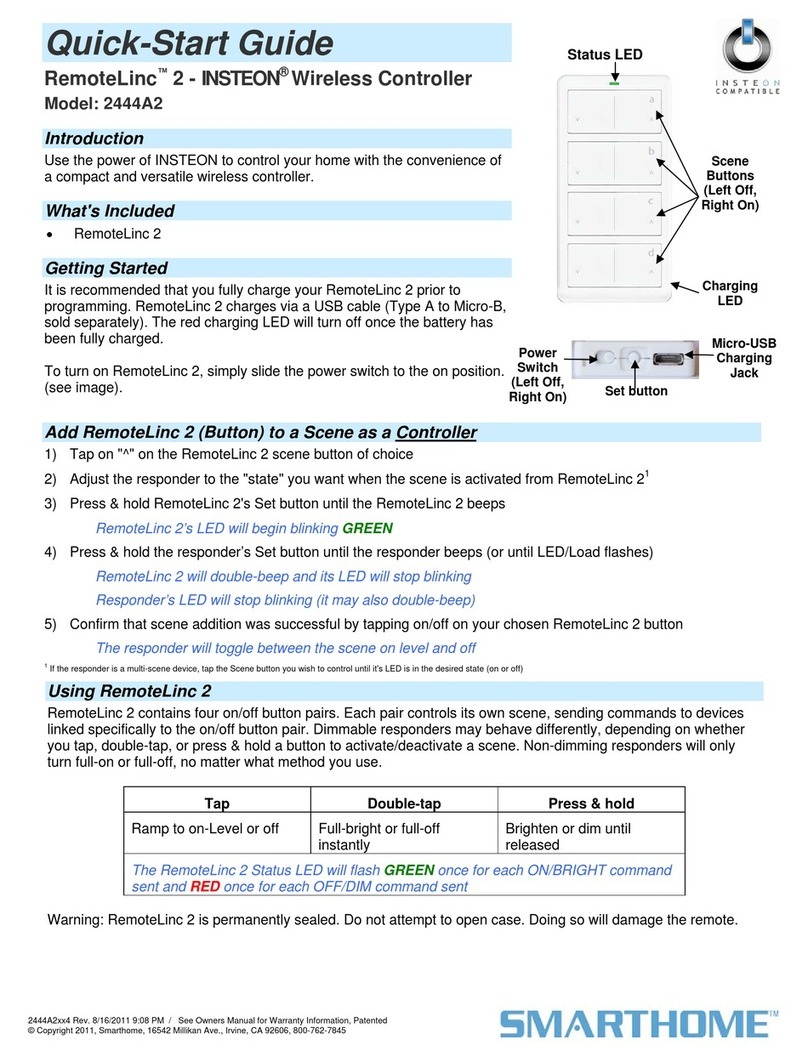
smart home
smart home RemoteLinc 2 INSTEON 2444A2 quick start guide
Hobby-Wing
Hobby-Wing WP-MAX10-SCT-120A- 4S-RTR user manual

