2
SPECIFICATIONS
1. POWER: 24 VDC ± 10%
400 mA min. (1 module)
3.5 Amps max. (16 modules + Expansion Card)
Must use NEC Class 2 or Limited Power Source (LPS) rated power supply.
2. COMMUNICATIONS:
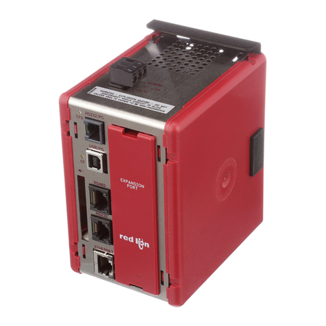
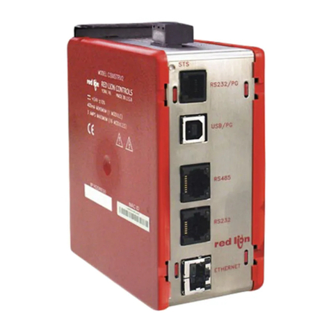
USB/PG Port: Adheres to USB specification 1.1. Device only using Type B
connection.
Serial Ports: Format and Baud Rates for each port are individually software
programmable up to 115,200 baud.
RS232/PG Port: RS232 port via RJ12
COMMS Ports: RS422/485 port via RJ45, and RS232 port via RJ12
DH485 TXEN: Transmit enable; open collector, VOH = 15 VDC,
VOL = 0.5 V @ 25 mA max.
Ethernet Port: 10 BASE-T / 100 BASE-TX
RJ45 jack is wired as a NIC (Network Interface Card).
3. LEDs:
STS – Status LED indicates condition of master.
TX/RX – Transmit/Receive LEDs show serial activity.
Ethernet – Link and activity LEDs.
CF – CompactFlash LED indicates card status and read/write activity
4. MEMORY:
On-board User Memory: 4 Mbytes of non-volatile Flash memory.
On-board SDRAM: 2 Mbytes
Memory Card: CompactFlash Type II slot for Type I and Type II cards.
Used for optional database storage only.
5. REAL-TIME CLOCK: Typical accuracy is less than one minute per month drift.
Battery: Lithium Coin Cell. Typical lifetime of 10 years at 25 ºC.
A “Battery Low” system variable is available so that the programmer can
choose specific action(s) to occur when the battery voltage drops below
its nominal voltage.
ThisunitisNOTfieldserviceable.Allworkmustbedonebyaqualifiedtechnician.
6. ENVIRONMENTAL CONDITIONS:
Operating Temperature Range: 0 to 50°C
Storage Temperature Range: -30 to +70°C
Operating and Storage Humidity: 80% max relative humidity,
non-condensing, from 0 to 50°C
Vibration According to IEC 68-2-6: Operational 5 to 150 Hz, in X, Y, Z
direction for 1.5 hours, 2 g.
Shock According to IEC 68-2-27: Operational 25 g, 11 msec in 3 directions.
Altitude: Up to 2000 meters
7. CONSTRUCTION: Case body is burgundy high impact plastic and stainless
steel. For indoor use only. Installation Category II, Pollution Degree 2.
8. POWER CONNECTION: Removable wire clamp screw terminal block.
Wire Gage Capacity: 24 AWG to 12 AWG
Torque: 4.45 to 5.34 in/lb (0.5 to 0.6 N-m)
9. MOUNTING: Snaps onto standard DIN style top hat (T) profile mounting
rails according to EN50022 -35 x 7.5 and -35 x 15.
10. CERTIFICATIONS AND COMPLIANCES:
SAFETY
Check each module’s specifications to determine system compliance.
UL Listed, File #E302106, UL508, CSA22.2 No. 14-M05 and File #E179259,
UL61010-1, CAN/CSA-C22.2 No. 61010-1; and File #E317425,ANSI/ISA
12.12.01-2007, CSA 22.2 No. 213-M1987
LISTED by Und. Lab. Inc. to U.S. and Canadian safety standards
IECEE CB Scheme Test Report #E179259-A5-CB-1
Issued by Underwriters Laboratories Inc.
IEC 61010-1, EN 61010-1: Safety requirements for electrical equipment
for measurement, control, and laboratory use, Part 1.
ELECTROMAGNETIC COMPATIBILITY
Emissions and Immunity to EN 61326: 2006: Electrical Equipment for
Measurement, Control and Laboratory use.
Immunity to Industrial Locations:
Electrostatic discharge EN 61000-4-2 Criterion B
4kV contact discharge
8kV air discharge
Electromagnetic RF fields EN 61000-4-3 Criterion B3
10V/m (80 MHz to 1 GHz)
3 V/m (1.4 GHz to 2 GHz)
1 V/m (2 GHz to 2.7 GHz)
Fast transients (burst) EN 61000-4-4 Criterion B
power 2kV
I/O signal 1kV
I/O signal connected to power 2kV
Surge EN 61000-4-5 Criterion B
power 1 kV L to L, 2 kV L to G
signal 1 kV
RF conducted interference EN 61000-4-6 Criterion A
3 Vrms
Emissions:
Emissions EN55011 Class A
Notes:
1. Criterion A: Normal operation within specified limits.
2. Criterion B: Temporary loss of performance from which the unit self-recovers.
3. The module’s with analog input and/or output signals may have their
signals deviate during disturbance but self-recover when the disturbance
is removed.
11. WEIGHT: 15.1 oz (456.4 g)
WARNING - DO NOT CONNECT OR DISCONNECT CABLES
WHILE POWER IS APPLIED UNLESS AREA IS KNOWN TO BE
NON-HAZARDOUS. USB PORT IS FOR SYSTEM SET-UPAND
DIAGNOSTICS AND IS NOT INTENDED FOR PERMANENT
CONNECTION.
WARNING - EXPLOSION HAZARD - DO NOT DISCONNECT
EQUIPMENT UNLESS POWER HAS BEEN SWITCHED OFF OR
AREA IS KNOWN TO BE NON-HAZARDOUS.
HARDWARE
INSTALLATION
DIN rail should be mounted horizontally so that the unit’s ventilation holes
are vertical in relation to cabinet orientation. A minimum clearance of 1 inch
(25.4 mm) should be maintained above and below the unit in order to ensure
proper thermal regulation.
The unit shall be installed inside a UL Listed Industrial Control Panel or
similar type of enclosure. A minimum 3.2 mm distance shall be maintained
between the hazardous live parts of the equipment and accessible parts of the
fire/electrical enclosure.
Figure 1 - Attach CSMSTR Master To DIN Rail and Remove
Rubber End Cap
1
2REMOVE
