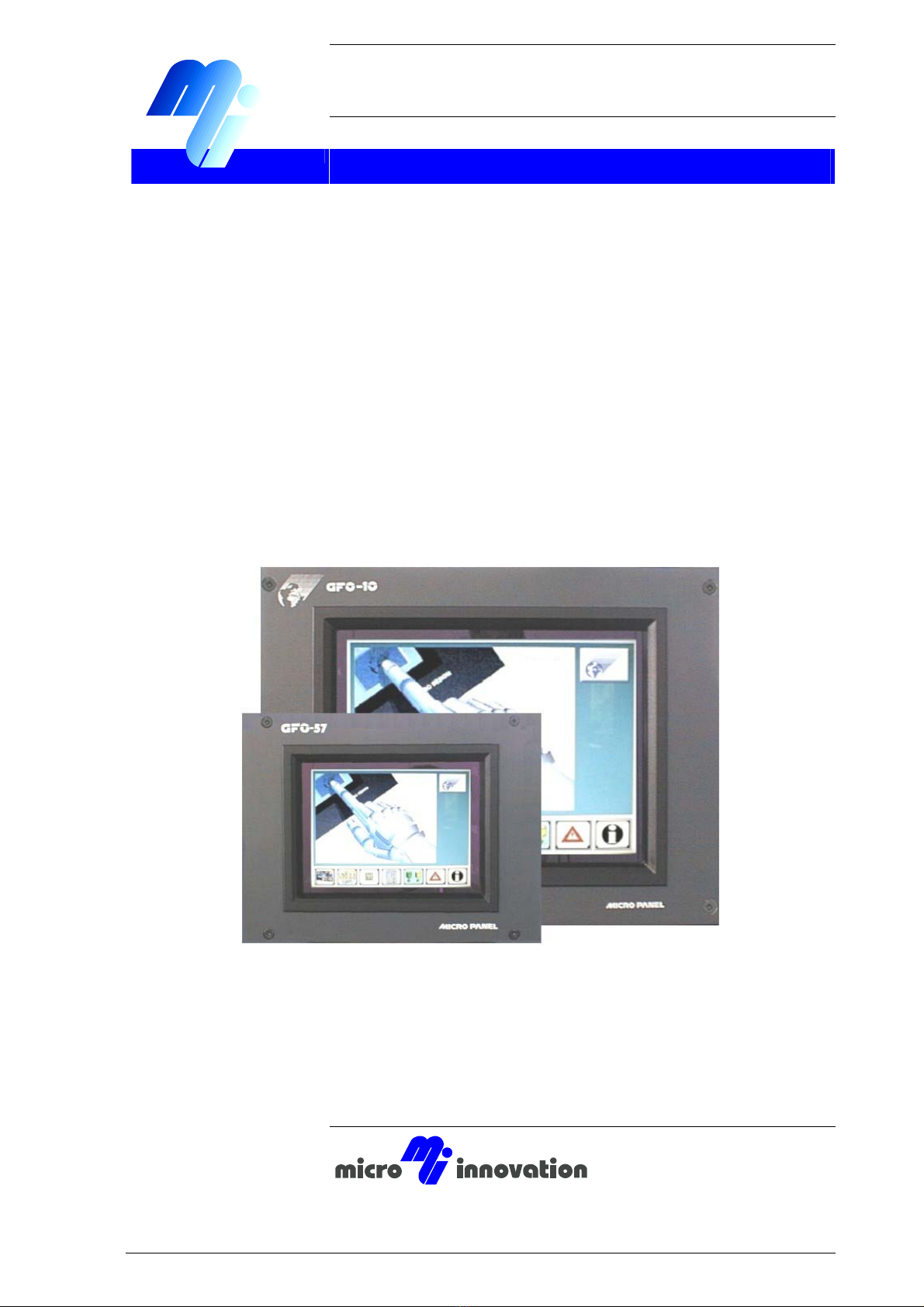
Device description GF0 MICRO PANEL
Contents
4
Technical subject to change
M000235-01.DOC
© by Micro Innovation
Contents
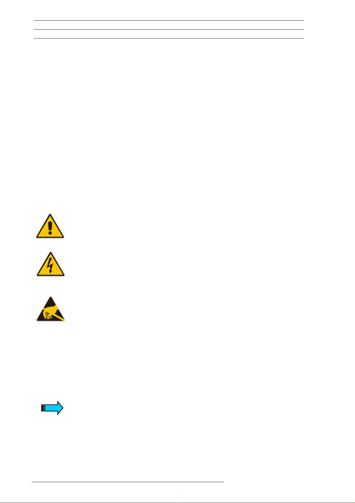
1Explanation of symbols...................................................................................... 6
2Introduction......................................................................................................... 7
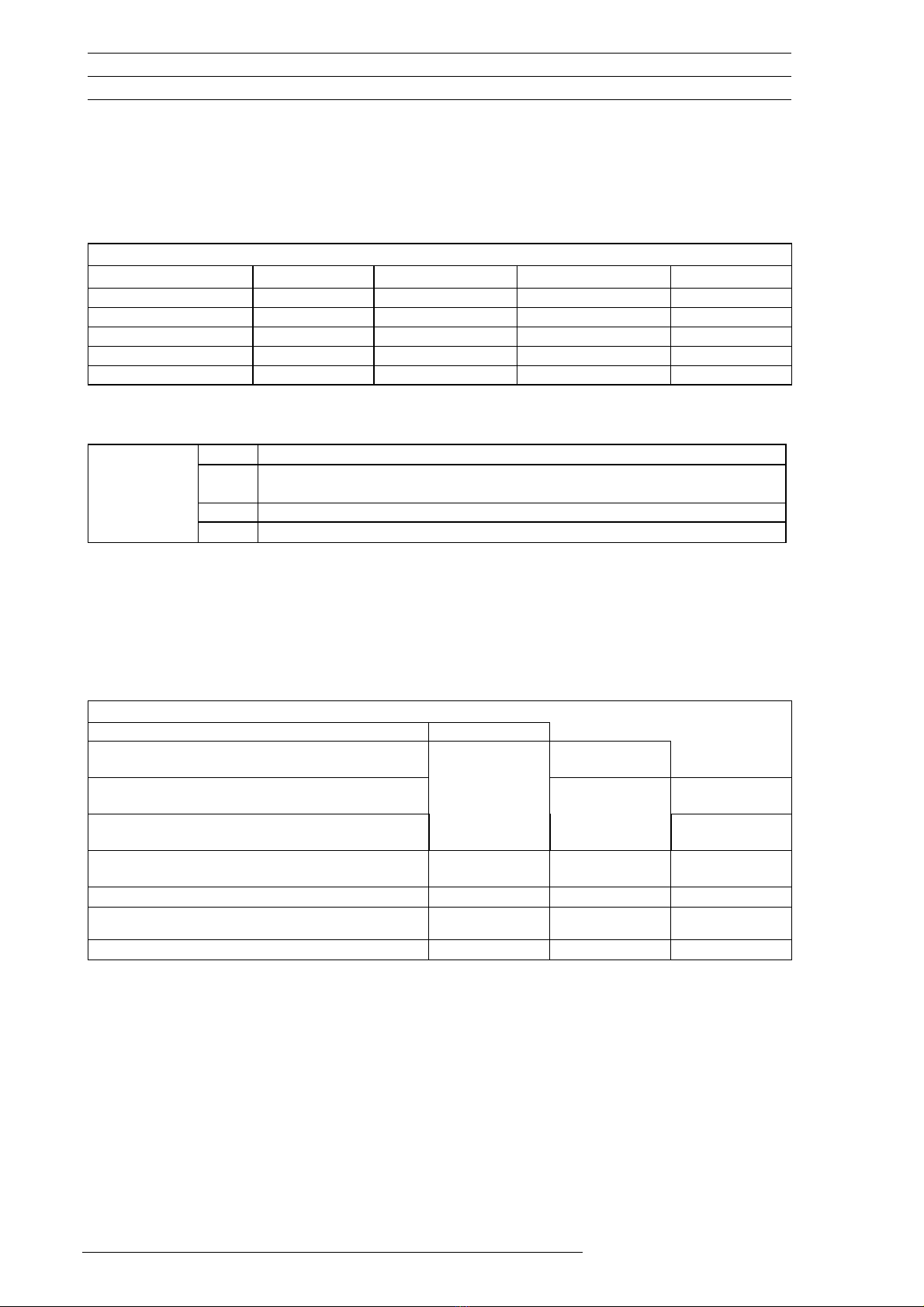
3Device Versions .................................................................................................. 8
3.1 Scope of Delivery .................................................................................................... 8
4Device mounting ................................................................................................. 9
4.1 General mounting instructions................................................................................. 9
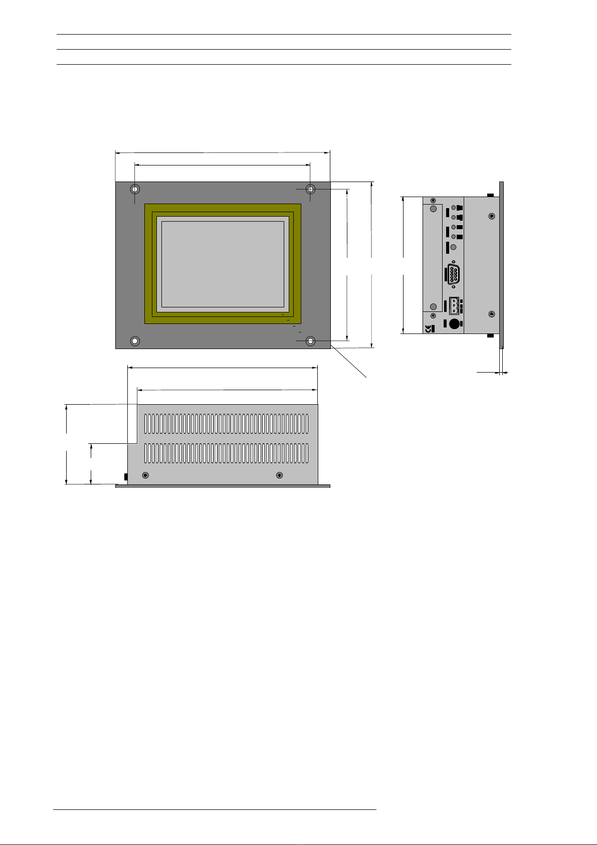
4.2 Dimensions of the 5.7" devices ............................................................................. 10
4.3 Front panel cutouts for 5.7" devices ...................................................................... 11
4.4 Dimensions of the 10" devices .............................................................................. 12
4.5 Front panel cutouts for 10" devices ....................................................................... 13
5Mounting instructions ...................................................................................... 14
5.1 Mounting (without special degree of protection).................................................... 14
5.2 Mounting according to degree of protection IP 65................................................. 14
6Connecting the system power supply ............................................................ 15
7Connection to the communication interface .................................................. 16
7.1 Preparing the connection cable (EMC).................................................................. 16
7.2 Preparing the shield connections .......................................................................... 17
8Connection and function of the programming port (PROG PORT) .............. 18
9Data transfer to the Micro Panel GF0 (Download button) ............................. 19
9.1 Loading the runtime (GRSW) ................................................................................ 20
9.2 Loading the project data (Download)..................................................................... 21
10 Communications Cards and COM SLOT ........................................................ 22
11 Expansion and configuration options............................................................. 23
11.1 General requirements......................................................................................... 23
11.2 Memory Expansion............................................................................................. 23
11.3 Additional 5V power supply on programming port (PROG PORT)..................... 24
12 Function and control LEDs .............................................................................. 25
13 Touch Screen .................................................................................................... 26
13.1 Prinzipielle Funktion des Touch-Screen............................................................. 26
13.2 Power up function test........................................................................................ 26
13.3 Cleaning and maintenance of the Touch Screen ............................................... 26
efesotomasyon.com - Klockner Moeller - inverter