Micro Rain MR43 User manual


Signs And Their Meaning...........................................................2
Identication Data........................................................................3
Machine Controls.........................................................................4
Weight And Dimensions..............................................................4
Transport And Delivery................................................................5
Assembly Instructions...........................................................6 - 8
Start-Up Maintenance Procedures.....................................9 - 11
Standard/Quick Hose Rewind...................................................12
Maintenance/Winterization........................................................13
Performance Chart.....................................................................14
Care And Repair Of P.E. Tube............................................14-15
Troubleshooting..........................................................................16
Warnings......................................................................................17
Use Of Shut-Off Valves.............................................................18
Booster Pump.............................................................................19
Table Of Contents

1
Thank you for purchasing a Micro Rain MR43 traveling sprinkler system. Please read
this manual carefully before operation in order to become familiar with all components and their
functions. Safety is the main priority and failure to follow these instructions may cause serious injury
or death. KID Group, Inc./Micro Rain is not responsible for machine failure or personal injury if these
procedures and operation instructions are not followed.
Caution
•Do not operate your Micro Rain traveler without a serious overview of
this manual
•Keep children and unauthorized people away from traveler
•Never allow children access to use the traveler
•Use caution when disconnecting couplings
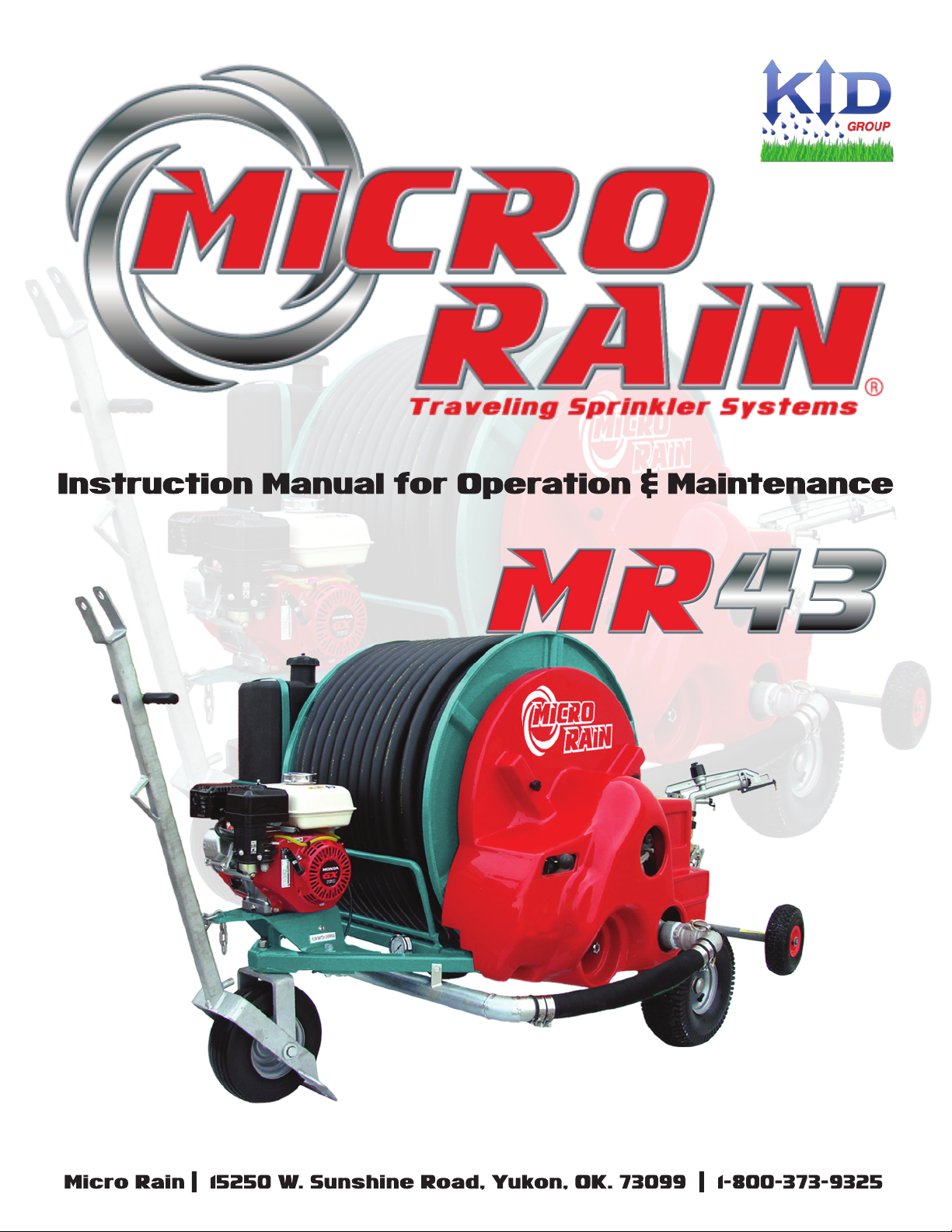
When the traveler shut-off valve activates, the supply hose remains pressurized at the end of
the run. First, relieve the pressure with the relief valve, then disconnect the supply hose.
•Use caution with the sprinkler heads
Pressurized water from the sprinkler head could cause serious damage to people or objects.
•Use caution during transport
Travelers are not made for public transit. Do not exceed 7 mph on at roads, or 2 mph on
steep inclines.
•Never service the traveler when it is in operation
Before servicing, stop the traveler and disconnect the supply line. All safety guards and
shields must be in place while operating the traveler.
•Beware of power lines
Irrigation water should never contact power lines or any other power source. Never let any
part of the traveler or any irrigation pipe get in contact with power source.

2
Signs & Their eanings
CAUTION
1. This sign indicates the operations and parts that may be risky for the safety
of the operator. When you see this sign, read following message carefully and
beware of possible risk of accident.
2. This sign indicates pressurized supply lines. Do not release the clamps
before making sure that the pressure is released.
3. This sign indicates dangerous equipment in operation. Never
use this machine with safety guards removed. When using a PTO
to rewind the hose, use only protected shafts, conforming with the
safety standards in force.
4. This sign indicates a risk of electric power danger. Never position the
sprinkler cart close to power supplies. Make sure that the sprinkled water
does not contact any power lines, houses, roads or any working sites.
5. Before operating the machine, read the instruction manual
carefully.
6. Before servicing or making any adjustments stop the machine
and disconnect the supply line.
7. Do not stand between the hose reel and gun cart while machine is in
operation.

3
The KID ID Plate includes a model number ie. MR43, MR58BP, and a serial number.
The ID plate is located on the left side of the machine (cover side) on the frame plat just
Special abels on Sprinkler Cart
Conditions for achine Operation
VALVE CAUTION GEARBOX WARNING
The Micro Rain machine is designed to be used with clean water suitable for irrigation.
This machine is not designed for dirty water or slurry/waste water conditions.

4
Drum Gear
(under cover)
Speed Control Lever
on Bypass Valve
Anti-Reverse Lever
Shut-off Valve Latch
Sprinkler Head w/
Adjustable Settings
Galvanized Tow Hitch
Booster Bump
Gearbox
Engage/Disengage
Handle
Drain Valve
(bottom side of gun cart)
PTO Rewind
Automatic Disengage Bar
eight & imensions
Dimensions (inches)
A B C D
MR43 76 59 50 50
Weight (pounds)
Dry w/ Water
MR43 559 806
Note: For unloading and assembly operations of the machine, use lift winches and equipment with dimensions and
capacities proportioned to the weight of the machine to be lifted. (see tables below)

5
Transport & elivery
Due to freight height and space limitations, some assembly may be required with your newly purchased
Micro Rain traveler. Be sure to follow proper procedures when unloading and assembling the machine
to avoid any danger or injury.
ATTENTION!!!
NEITHER MICRO RAIN NOR MICRO RAIN DEALERS ARE RESPONSIBLE FOR ANY
INJURY OR MACHINE FAILURE DUE TO LACK OF PROPER SAFETY PROCEDURES
OR FAILURE TO READ AND FOLLOW INSTRUCTIONS.
1) Micro Rain travelers are either shipped on a special skid (partially disassembled) which can be
unloaded with a fork lift, or they are shipped in a fully assembled state by blocking on the shipping oor.
2) The proper procedure to unload the skid shipment is with a fork lift or equivalent.
Standard packaging and pallet shipping for Micro Rain travelers.

6
ssembly
Due to freight height and space limitations, some assembly may be required with your newly purchased
Micro Rain traveler. Be sure to follow proper procedures when unloading and assembling the machine
to avoid any danger or injury.
ATTENTION!!!
NEITHER MICRO RAIN NOR MICRO RAIN DEALERSARE RESPONSIBLE FOR ANY
INJURY OR MACHINE FAILURE DUE TO CARELESSNESS OR FAILURE TO READ
AND FOLLOW INSTRUCTIONS!!!.
1. Assemble the Gun Cart, (Figure 1).
a. Push the end of the P.E. hose onto the guncart as indicated in (Figure 1). Applying heat to
the end of the P.E. hose will ease this process.
b. Tighten the clamp provided, with the bolts on top.
c. Mount the sprinkler gun onto the gun cart. Use teon tape or a thread compound to
provide a proper seal.
d. Using the hand grip, pick up the gun cart and hook it onto machine, (Figure 2).
Figure 1 Figure 2

7
ssembly nstructions
Your Micro Rain traveler is packaged for protection during shipping with the guncart and sprinkler
head dis-assembled. The instructions below will step you through the assembly of the guncart and
attaching the guncart onto the end of the poly hose. Please follow these instructions carefully to
ensure that your traveler is assembled properly upon start up. If you have any questions, call for
technical assistance at 800-373-9325.
1. Cut strapping and remove Micro Rain and guncart from pallet.
Remove the snap ring on the end of the guncart axle and slide
wheels onto guncart axle and re attach snap ring and washer
as shown above. Attach sprinkler head as shown above.
2. Pull and lock anti-reverse knob to release reel allowing hose
to unwind.
3. Untie hose end and pull hose through hose guide bars.
4. Cut the end of the poly hose off just past the notched section
that is used for shipping. (Keep hold of the hose end still
attached to the machine so that it does not slip back through
the guide and uncoil any wraps on the machine. Always keep
machine coils tight!)

8
ssembly nstructions
5. Bevel the inside of the hose to allow the barbed portion of the
guncart to have an easier start into the poly tube. (At this time,
slide the hose clamps onto the hose so they are in place and
ready to tighten after hose is connected.)
6. Heat the end of the poly hose to make it softer when inserting
the barbed portion of the cart. Only a small amount of heat
is needed. Do not overheat and melt the tube.
7. Take the cart in one hand and the poly hose in the other hand.
Insert the barb of cart into the hose while the tube is hot and
work in an up and down motion moving the poly hose onto
the barb.
8. Attach clamps with the bolt heads straight up on the top side of
the hose to allow clearance into the hose guide.

9
1. Check the oil level of the gearbox and if necessary add SAE
80W/90. Keep oil level at the side plugs in the gearbox in
order to bathe the shift fork in oil.
2. Grease the machine thoroughly (all grease ttings) and
thereafter, grease every 100 hours. Pay close attention
to the two grease ttings on the drum inlet. One grease
tting is located on the bottom side and lubricates the
drum inlet seals. Grease must be spread on the drum
gear teeth and at the drive shaft where the drum gear
and drive gear mesh. The scroll bar must also be kept
well greased, and the scroll knife must be lubricated
(grease tting) in order to function correctly.
3. Check the tire pressure and if necessary, inate to pressure
recommended on the tire (generally 35 PSI).
LUBRICANT TABLE
Gearbox SAE 80W/90
Reel Supports Grease NLGI No.2
Grease Fittings Grease NLGI No.2

10
The MR43 is designed for clean water suitable for irrigation. The machine is not designed for water
that includes large pieces of debris or slurry/wastewater conditions.
1. Tow the machine to the working site (off-road only).
WARNING!! Maximum speed is 7 MPH. Before towing the
machine, be sure no one is standing behind or around the
machine; make sure the gun cart is racked.
2. Face the gun cart side of the reel towards the area needing to
be irrigated. The machine direction should be as straight
as possible. Set the stabilizer.
3. Lower the gun cart.
4. Connect the water supply hose to the water inlet connection
on the machine.
NOTE: Before connecting the supply hose to the machine, ush
out hose or check to be sure there is no foreign matter which
will block the turbine.
5. Release the backstop (anti-reverse) lever. Pull straight back and
down to release.
6. IMPORTANT!! Make sure the gearbox lever is in the
disengaged or idle position before unwinding tube.

11
11. When you have pulled out the hose, make sure that the wraps
remaining on the reel are tight and close together next to
the edge of the drum. If necessary, roll the drum by hand
to tighten wraps, and push them in place by hand. This
adjustment must be done when machine is not in operation.
IMPORTANT! The rst time using the machine it is very important
to pull out all but 1 or 2 wraps of hose in order to check the level
wind setting. Remove any loose wraps that may have been created
in shipping. If level wind setting needs adjusting, contact your Micro
Rain dealer for instructions.
**Important: Always pull cart out straight and tighten loose wraps before start up!
ALWAYS PULL TUBE
OUT STRAIGHT!
KEEP WRAPS TIGHT!
8. Pull the gun cart out straight with a consistent speed (about the
pace of a walk), and slow down when approaching the stop or
end position.
NOTE: Always leave at least one wrap of hose on the reel.
9. Pull up on shut off valve handle to place into operational position
(open valve). This procedure must be completed with the water
source off and the sprinkler pointed away from any individuals.
10. Re-engage the anti-reverse handle and start water ow. Turn
speed control valve to the fast setting (full counter-clockwise)
and engage gearbox. Turn speed control in the clockwise
direction to slow reel to the desired speed. If you have a
computer speed control system, see page 10 for specic
instructions on operation.

12
1) Release the back stop (anti-reverse) into the operating position by gently lifting
handle until it releases from the locked position.
2) Turn the water supply on and increase the machine pressure until it reaches the
desired operating pressure.
3) Engage the gearbox with the gearbox handle, to put the reel into rewind motion.
IMPORTANT!!! Never force this lever into gear. Forcing into gear will irre-
vocably damage the gearbox and void the warranty. Lever should be pushed
gently into gear, allowing the gears to mesh. This process is best completed
with water running through the turbine.
Standard ose ewind
Quick ose ewind
4) Adjust hose retraction speed. On a manual speed control machine, this is com
pleted by adjusting the position of the bypass valve. Full reel speed is achieved
with the valve turned full counterclockwise. To slow the retraction speed, slowly
turn the bypass valve clockwise until the desired retraction speed is obtained. On
computer speed control machines, speed is adjusted by entering the desired re-
traction rate (feet/hour) on the computer key pad. The speed can be adjusted any
time in operation by using the + or - buttons on the key pad. See the Golden
Rain manual for specic instructions concerning the computer setting/operation.
The purpose of the PTO shaft on the gearbox is to rewind the hose quickly by using the tractor. If for any reason you need
to wind the hose up quickly then follow these steps.
1. WARNING! Make sure the handle on the gearbox is in the idle or disengaged position, otherwise severe damage will
occur to the gearbox. Disengage the anti-reverse lever.
2. Connect the tractor PTO drive line to the gearbox shaft on the Micro Rain. WARNING! Read drive-line directions for
proper use of the PTO drive-line. Neither Micro Rain nor Micro Rain dealers are responsible for improper use of the drive
line which can result in injury or death.
3. Slowly activate the tractor power take off and the reel will begin to wind up. Roll up hose at the slowest possible RPM.
IMPORTANT!! Do not engage PTO with high RPM. This can damage the drive gear.
IMPORTANT!! When using the PTO shaft, there is no automatic stop at the end of the run. The PTO must therefore be
stopped before the hose is completely wound up to avoid damage to the gun cart or the end of the hose. It is recommended
the nal wrap or two to be wound up manually.
IMPORTANT!! To avoid irregular rewinding of the hose when using a PTO, it may be necessary to wind the hose up
under water pressure to avoid excessive ovaling of the hose.

13
interization
1. Disconnect supply hose from machine to allow any waler In and
above inlet ttings to drain out.
2. Drain plug on the bottom of the turbine must be drained to prevent
freeze damage to turbine housing and impeller. Drain plug is lo-
cated on the bottom side of the turbine.
3. It is important ti unrack the guncart on the MR40 & MR43, open
the shutoff valve, and allow water above lhe valve to drain out of the
sprinkler. Shutoff valve on MR50 throughMR58RL located under
the red cover should be latched in the open position as well. This
will allow any remaining water to expand out and not cause any
damage to the valve.
4. Drain guncart body by taking out draln plug localed on the bottom
elbow of the cart on all large chassis Micro Rains - MR40 through
MR5BRL.
5. Drain boost pump case by opening 1/4” ball valve as shown in left
photo. On boost pump models, disconnect the short black con-
nection hose on the side of the Micro Rain that connects the
boost pump piping to the inlet side of the machine. This allows
water in the cross-pipe to drain; preventing damage to the pipe or
ow switch.
aintenance Schedule
Fittings & Seals: Grease ttings and seals every 100 hours.
Wheel Hubs: Grease all wheel hubs every 100 hours.
Drum Gear: Grease the drum gear at least twice per season.
Gearbox: Change gearbox oil once a season with 80W/90 gear oil.
Level Wind: Check tire pressure every 4-6 weeks.
NOTE: Water left in poly hose may be blown out with an air compressor by coverting an Inlet tting with an air chuck
adaptor. These ttings are available through KID Group if needed.

14
Care of the olyethylene Tube
The polyethylene tube ( P. E. Tube ) is a very durable and will serve your irrigation needs for many
years with proper care and handling. Observe these simple precautions when using your Micro Rain
traveler to prevent damaging or shortening the life of your tube.
1. The rst time you unwind the tube, pull off all but a couple of wraps. This will allow you to check
the level-wind position, and make sure there are no loose wraps left from shipping.
2. Always transport your machine with the anti-reverse lever engaged, and cart racked.
3. Do not attempt to operate the machine with loose or misplaced wraps of tube. Tighten the tube
on the drum before starting the machine. WARNING!! Starting the machine without tightening
the tube wraps will result in miswrapping and could permanently damage your tube.
4. Do not attempt to move or relocate the machine with tube unwound. All the tube must be wound
on the machine drum before moving.
5. While the tube is unwound make certain never to drive anything across the tube.
6. Be careful when operating other equipment near the unwound tube.
7. Never sharply bend or kink the tube. It will not ex back, and it will be permanently damaged.
erformance Chart
NOTICE: These specications are for a guide only and are based on theoretical calculations and performance tests. This is to be
used as a guide only, as performance may vary under eld conditions.

15
REPAIR COUPLER FOR P.E. TUBE
Screw-in menders are the best way to repair damaged P. E. tube in the field. These metal menders will
allow you to repair damaged tube without replacing the entire length of tube. These tube menders can be
obtained from your Micro Rain dealer.
INSTALLATION
1. Cut the tube with a hack-saw on either side of the damaged area. Make sure your cuts are straight.
Place expansion collar over each end of tube ( fig 1 ).
FIG 1
2. Chamfer/bevel the inside and outside of the tube with a knife or file, so that the threads of the metal
mender will enter the tube.
3. NOTE!! The threads on the metal mender are lefthand threads on one end and righthand threads
on the other. Screw the mender in one end about 2/3 of the way using a wrench. Then unscrew it.
Repeat the procedure on the other end. Remember one end is left-hand thread. Do not apply heat to
the tube during this procedure ( fig 2 ).
FIG 2
4. Complete the procedure by starting the threads in both ends at the same time, turning the mender
with a wrench. Screw the mender all the way into the tube until the two ends meet and are snug
(fig 3).
FIG 3
17

16
Troubleshooting
The impeller of the turbine is blocked by foreign matter.
The gun is partly clogged and only a small amount of water
comes out.
The injection nozzle in the turbine is clogged.
The gun nozzle is too small, compared to the machine model.
Not enough water volume or pressure at the machine inlet.
The gearbox has been damaged.
The machine legs are improperly placed.
The hose is on damp soil or grass which produces too much
drag.
SOLUTION: Remove the turbine cover and clean the
housing.
SOLUTION: Proceed to clean out gun nozzle.
SOLUTION: Disassemble the hose at the turbine entry
and clean out.
SOLUTION: Replace with a larger gun nozzle or a smaller
injection nozzle.
SOLUTION: Increase volume and/or pressure.
SOLUTION: Repair the gearbox.
SOLUTION: Reposition leg to create more friction.
SOLUTION: Wait until the soil has dried or pick up hose
and place blocks of wood under in order to
reduce friction.
IF HOSE DOES NOT WIND UP.....
MACHINE WON’T STAY ANCHORED OR SLIDES.....
RECOMMENDATIONS
• When moving the machine never exceed the maximum speed of 7 MPH.
• If the hose is wound up using the PTO, be certain the gearbox is in the idle or disengaged position, or the
gearbox will be seriously damaged.
• At the beginning of each season, completely unwind the hose, leaving only two wraps on the reel.
• ANY MODIFICATION MADE TO ANY PART OF THE MACHINE WILL VOID THE WARRANTY.
• If the hose remains unwound on the ground for an extended period of time ( several hours ), it may stick to the
ground. Prior to starting the machine, take a rope and drag underneath the tube from one end to the other,
avoiding any damage due to too much friction.
• If the machine is being used on several short elds, the hose may miswrap, or not continue to roll up correctly.
If this happens, unwind the hose with only two wraps remaining on the drum, allowing the machine to rewind
properly.
• THE MACHINE MUST NOT BE OPERATED WITHOUT THE PROTECTION GUARDS
• MPORTANT!! Failure to observe these instructions, the use of non original spare parts, or unauthorized
changes to the machine will void the warranty.

17
arnings and isks
MICRO RAIN AND MICRO RAIN DEALERS ARE NOT RESPONSIBLE
FOR ANY INJURY OR DAMAGE DONE DUE TO FAILURE TO FOLLOW
SAFETY GUIDELINES
Despite Micro Rain’s attempt to a make a safe and secure machine, some risks still remain un avoidable
in the operation of the machine. Failure to heed these warnings can cause serious injury or
death.
When pulling out the hose no one should be standing on or around the machine unless authorized to
do so.
No part of the body should ever be between the hose and the reel when the machine is in use. This
applies especially to unauthorized people.
When the machine is being transported on a grade of 6 degrees or greater, there is a risk of the
machine overturning. Take every precaution to avoid transporting on steep grades.
Make sure that in the rain gun (sprinkler head) path of irrigation there are no electrical wires or power
lines.
Tremendous water pressure comes through the hose to the gun. Avoid standing by or near the
direction of the sprinkler gun.
Never remove the quick connect couplings on the machine while water pressure is being supplied to
the machine.
Be very careful when transporting the machine. Use safety measures when towing. When irrigating
be sure sprinkler head is not pointing toward objects or individuals unaware of the powerful jet-stream.

18
se Of The Shut-Off alves
STANDARD CART SHUT-OFF VALVE
OPTIONAL SHUT OFF VALVE FOR HIGH CART MR43
1. The valve handle must be pulled upward and locked into position for irrigation. The handle should
only be placed into this open position (Figure 1) with the water source off and the sprinkler
pointed away from all individuals. The valve could still be under pressure from a previous
irrigation run. Always use caution when opening the valve.
2. When the cart approaches the machine, the shut-off bar will trip the shut-off valve and the water
will stop owing. This stops the machine. The shut-off valve handle will now be in the down
position (off position). (Figure 2)
3. Prior to re-pulling the cart out for the next irrigation run, shift the gearbox back into neutral. The
gearbox will be seriously damaged if the hose is unwound with the gearbox still engaged.
1. In order for water to enter the machine, the shut off valve (located under the red side cover) must
be manually opened prior to irrigating. Remove the assist handle from the holder and place in the
valve arm.
2. Pull valve open using the assist handle. The valve will latch and hold in the open position. Note:
The latching mechanism occurs automatically when the tube rider is below the rst wrap. You are
now ready to attach the supply hose and start the water supply.
3. Adjust shut off valve adjustment block if needed. The shut off should actuate just prior to the
gearbox being shifted to the neutral position.
Figure 1 Figure 2
Table of contents