Toro Groundsmaster 4300-D User manual

FormNo.3441-889RevA
22-inchRotaryCuttingUnit
Groundsmaster®4300-DTractionUnit
ModelNo.30845—SerialNo.310000001andUp
Registeratwww.Toro.com.
OriginalInstructions(EN)*3441-889*

ThisproductcomplieswithallrelevantEuropean
directives.Fordetails,pleaseseetheDeclarationof
Incorporation(DOI)atthebackofthispublication.
WARNING
CALIFORNIA
Proposition65Warning
Useofthisproductmaycauseexposure
tochemicalsknowntotheStateof
Californiatocausecancer,birthdefects,
orotherreproductiveharm.
Introduction
Thisrotary-bladelawncuttingdeckismounted
toaride-onmachineandisintendedtobeused
byprofessional,hiredoperatorsincommercial
applications.Itisprimarilydesignedforcuttinggrass
onwell-maintainedlawnsinparks,sportselds,
andoncommercialgrounds.Usingthisproductfor
purposesotherthanitsintendedusecouldprove
dangeroustoyouandbystanders.
Readthisinformationcarefullytolearnhowtooperate
andmaintainyourproductproperlyandtoavoid
injuryandproductdamage.Youareresponsiblefor
operatingtheproductproperlyandsafely.
Visitwww.Toro.comforproductsafetyandoperation
trainingmaterials,accessoryinformation,helpnding
adealer,ortoregisteryourproduct.
Wheneveryouneedservice,genuineT oroparts,or
additionalinformation,contactanAuthorizedService
DealerorT oroCustomerServiceandhavethemodel
andserialnumbersofyourproductready.Themodel
andserialnumbersarestampedonaplateonthe
rearofthecuttingunit,underthecover.Writethe
numbersinthespaceprovided.
ModelNo.
SerialNo.
Thismanualidentiespotentialhazardsandhas
safetymessagesidentiedbythesafety-alertsymbol
(Figure1),whichsignalsahazardthatmaycause
seriousinjuryordeathifyoudonotfollowthe
recommendedprecautions.
g000502
Figure1
1.Safety-alertsymbol
Thismanualuses2wordstohighlightinformation.
Importantcallsattentiontospecialmechanical
informationandNoteemphasizesgeneralinformation
worthyofspecialattention.
Contents
Safety.......................................................................3
GeneralSafety...................................................3
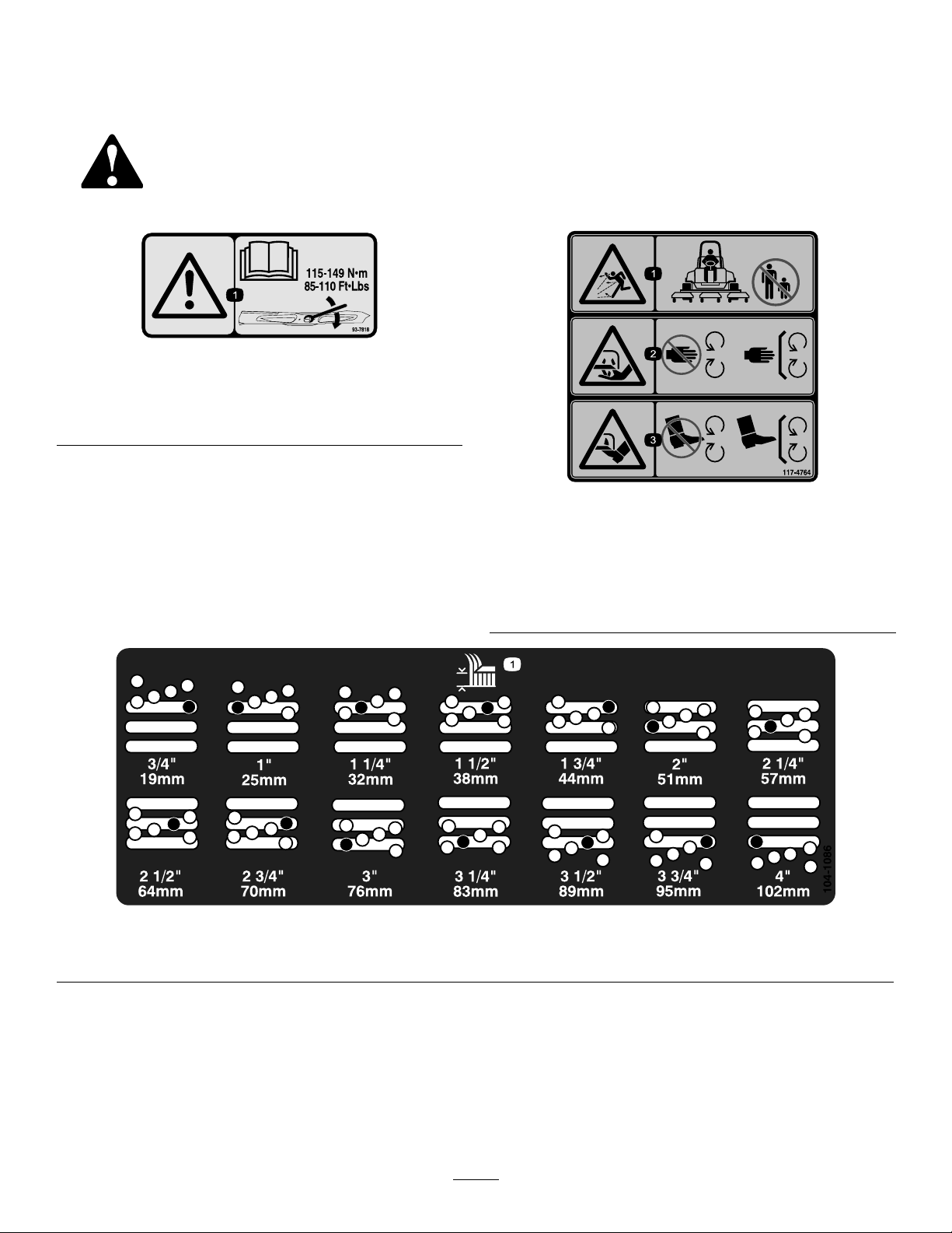
SafetyandInstructionalDecals..........................4
Setup........................................................................5
PreparingtheMachine........................................5
MountingtheCuttingUnittotheTraction
Unit.................................................................5
AdjustingtheHeight-of-Cut.................................6
AdjustingtheRollerScraper...............................6
InstallingtheMulchingBafe..............................7
ProductOverview.....................................................7
Specications....................................................7
Attachments/Accessories...................................7
Operation..................................................................8
SelectingaBlade................................................8
OperatingTips...................................................9
Maintenance...........................................................10
RecommendedMaintenanceSchedule(s)...........10
GreasingtheBearings......................................10
SeparatingtheCuttingUnitfromtheTraction
Unit...............................................................10
MountingtheCuttingUnittotheTraction
Unit................................................................11
ServicingtheCuttingBlades..............................11
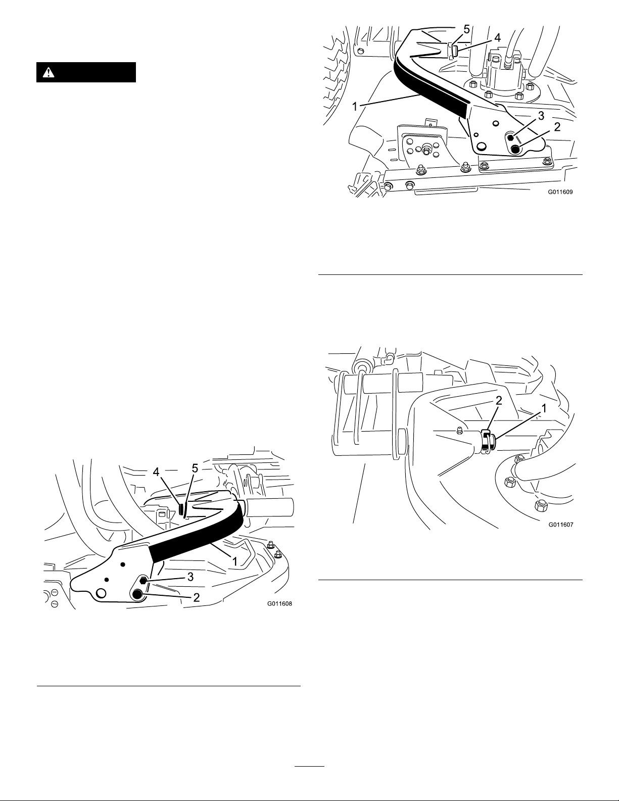
ServicingtheFrontRoller.................................14
Storage...................................................................15
©2020—TheToro®Company
8111LyndaleAvenueSouth
Bloomington,MN554202
Contactusatwww.Toro.com.
PrintedintheUSA.
AllRightsReserved

Safety
Thiscuttingunitmeetsapplicablestandardswhen
installedonthetractionunit.
GeneralSafety
Thisproductiscapableofamputatinghandsand
feetandofthrowingobjects.Alwaysfollowallsafety
instructionstoavoidseriouspersonalinjury
•Readandunderstandthecontentsofthis
Operator’sManualbeforestartingthemachine.
•Useyourfullattentionwhileoperatingthe
machine.Donotengageinanyactivitythat
causesdistractions;otherwise,injuryorproperty
damagemayoccur.
•Donotputyourhandsorfeetnearmoving
componentsofthemachine.
•Donotoperatethemachinewithoutallguards
andothersafetyprotectivedevicesinplaceand
functioningproperlyonthemachine.
•Keepclearofanydischargeopening.
•Keepbystandersandchildrenoutoftheoperating
area.Neverallowchildrentooperatethemachine.
•Beforeyouleavetheoperator’sposition,dothe
following:
–Parkthemachineonalevelsurface.
–Lowerthecuttingunit(s).
–Disengagethedrives.
–Engagetheparkingbrake(ifequipped).
–Shutofftheengineandremovethekey.
–Waitforallmovementtostop.
Improperlyusingormaintainingthismachinecan
resultininjury.Toreducethepotentialforinjury,
complywiththesesafetyinstructionsandalways
payattentiontothesafety-alertsymbol,which
meansCaution,Warning,orDanger—personalsafety
instruction.Failuretocomplywiththeseinstructions
mayresultinpersonalinjuryordeath.
3

SafetyandInstructional
Decals
Safetydecalsandinstructionsareeasilyvisibletotheoperatorandarelocatednearanyarea
ofpotentialdanger.Replaceanydecalthatisdamagedormissing.
decal93-7818
93-7818
1.Warning—readtheOperator'sManualforinstructionson
torquingthebladebolt/nutto115to149N∙m(85to110
ft-lb).
decal117-4764
117-4764
1.Thrownobjecthazard—keepbystandersaway.
2.Cuttinghazardofhand,mowerblade—stayawayfrom
movingparts;keepallguardsandshieldsinplace.
3.Cuttinghazardoffoot,mowerblade—stayawayfrom
movingparts;keepallguardsandshieldsinplace.
decal104-1086
104-1086
1.Heightofcut
4

Setup
WARNING
Ifyouleavethekeyintheswitch,someone
couldaccidentallystarttheengineand
seriouslyinjureyouorotherbystanders.
Removethekeyfromtheswitchbeforeyou
installthecuttingunit
Note:Determinetheleftandrightsidesofthe
machinefromthenormaloperatingposition.
PreparingtheMachine
1.Parkthemachineonalevelsurface.
2.Engagetheparkingbrake.
3.Shutofftheengineandremovethekey.
MountingtheCuttingUnit
totheTractionUnit
1.Pivotthecarrierframeandsecureittothedeck
bracketwiththeagpin,boltandnut.Positionit
asshowninFigure2.
Note:Forrearcuttingunits,pivotthecarrier
frameforward(Figure2).Forfrontcuttingunits,
pivotthecarrierframerearward.
g011608
Figure2
1.Carrierframe4.Liftarmpivotpin
2.Flagpin5.Lynchpin
3.Boltandnut
g011609
Figure3
1.Carrierframe4.Liftarmpivotpin
2.Flagpin5.Lynchpin
3.Boltandnut
2.Movethecuttingdeckintopositioninfrontof
thetractionunit.
3.Slidethedeckcarrierframeontolift-armpivot
pinandsecureitwiththelynchpin(Figure4).
g011607
Figure4
1.Lift-armpivotpin2.Lynchpin
4.Installthehydraulicmotortothedeck(Figure
5).MakesurethattheO-ringisinpositionand
notdamaged.
5

g011619
Figure5
1.Motor-mountingscrews
5.Greasethespindle.
AdjustingtheHeight-of-Cut
Important:Thecuttingunitsoftencut
approximately6mm(1/4inch)lowerthanareel
cuttingunitwiththesamebenchsetting.It
maybenecessarytosetthecutting-unitbench
measurementat6mm(1/4inch)abovethatofreel
cuttingunitscuttinginthesamearea.
Important:Accesstotherearcuttingunitsis
greatlyimprovedbyremovingthecuttingunit
fromthemachine.
1.Parkthemachineonalevelsurface,engage
theparkingbrake,lowerthecuttingunittothe
ground,shutofftheengine,andremovethekey.
2.Loosentheboltsecuringeachheight-of-cut
brackettotheheight-of-cutplate(frontandeach
side)asshowninFigure6.
3.Beginningwithfrontadjustment,removethe
bolt.
g011344
Figure6
1.Heightofcutbracket3.Spacer
2.Heightofcutplate
4.Whilesupportingthechamber,removethe
spacer(Figure6).
5.Movethechambertothedesiredheightof
cutandinstallaspacerintothedesignated
height-of-cutholeandslot(Figure7).
g201855
Figure7
6.Positionthetappedplatein-linewiththespacer..
7.Installtheboltngertight.
8.Repeatsteps4through7foreachside
adjustment.
9.Torqueall3boltsto41N∙m(30ft-lb).Always
tightenthefrontboltrst.
Note:Adjustmentsofmorethan3.8cm(1-1/2
inches)mayrequiretemporaryassemblytoan
intermediateheighttopreventbinding(e.g.,
changingfrom3.1to7cm(1-1/4to2-3/4inches)
heightofcut).
AdjustingtheRoller
Scraper
Optional
Theoptionalrearrollerscraperfunctionsbestwhen
thereisanevengapof0.5to1mm(0.02to0.04inch)
betweenthescraperandtheroller.
1.Loosenthegreasettingandthemounting
screw(Figure8).
g031578
Figure8
1.Rollerscraper3.Greasetting
2.Mountingscrew
6

2.Slidethescraperupordownuntilyouobtaina
gapof0.5to1mm(0.02to0.04inch)between
therodandtheroller.
3.Tightenthegreasettingandscrewto41N∙m
(30ft-lb)inanalternatingsequence.
InstallingtheMulching
Bafe
Optional
ContactyourauthorizedTorodistributorforthecorrect
mulchingbafe.
1.Thoroughlycleandebrisfromthemountingholes
ontherearwallandleftwallofthechamber.
2.Installthemulchingbafeintherearopening
andsecureitwith5ange-headbolts(Figure9).
g031579
Figure9
1.Mulchingbafe2.Flange-headbolt
3.Verifythatthemulchingbafedoesnotinterfere
withthetipofthebladeanddoesnotprotrude
insidethesurfaceoftherearchamberwall.
DANGER
Usingthehigh-liftbladewiththe
mulchingbafecouldcausetheblade
tobreak,resultinginpersonalinjuryor
death.
Donotusethehigh-liftbladewiththe
bafe.
ProductOverview
Specications
Note:Specicationsanddesignaresubjectto
changewithoutnotice.
Length80.8cm(31.8inches)
Width72.1cm(28.4inches)
Height21.6cm(8.5inches)
tocarriermount
26.7cm(10.5inches)
at3/4inchheightof
cutwithdrivemotor
34.8cm(13.7inches)at
4inchheightofcutwithdrive
motor
Netweight63.5kg(140pounds)
Attachments/Accessories
AselectionofT oroapprovedattachmentsand
accessoriesisavailableforusewiththemachine
toenhanceandexpanditscapabilities.Contact
yourAuthorizedServiceDealerorauthorizedToro
distributororgotowww.T oro.comforalistofall
approvedattachmentsandaccessories.
Toensureoptimumperformanceandcontinuedsafety
certicationofthemachine,useonlygenuineT oro
replacementpartsandaccessories.Replacement
partsandaccessoriesmadebyothermanufacturers
couldbedangerous,andsuchusecouldvoidthe
productwarranty.
7

Operation
Note:Determinetheleftandrightsidesofthe
machinefromthenormaloperatingposition.
CAUTION
Ifyouleavethekeyintheignitionswitch,
someonecouldaccidentlystarttheengine
andseriouslyinjureyouorotherbystanders.
Removethekeyfromtheignitionbeforeyou
doanymaintenance.
SelectingaBlade
StandardCombinationSail
Thisbladewasdesignedtoprovideexcellentliftand
dispersioninalmostanycondition.Ifmoreorlesslift
anddischargevelocityisrequired,consideradifferent
blade.
Attributes:Excellentliftanddispersioninmost
conditions
AngledSail(NotCECompliant)
Thebladegenerallyperformsbestinlowerheightsof
cut—1.9to6.4cm(3/4to2-1/2inches).
Attributes:
•Dischargeremainsmoreevenatlowerheightsof
cut.
•Dischargehaslesstendencytothrowleftandthus
acleanerlookaroundbunkersandfairways.
•Lowerpowerrequirementatlowerheightsand
denseturf.
High-LiftParallelSail(NotCE
Compliant)
Thebladegenerallyperformsbetterinthehigher
heightsofcut—7to10cm(2to4inches).
Attributes:
•Moreliftandhigherdischargevelocity
•Sparseorlimpturfispickedupsignicantlyat
higherheightsofcut
•Wetorstickyclippingsaredischargedmore
efcientlyreducingcongestioninthedeck
•Requiresmorehorsepowertorun
•Tendstodischargefurtherleftandcantendto
windrowatlowerheightsofcut
WARNING
Usingahigh-liftbladewiththemulchingbafe
couldcausethebladetobreak,resultingin
personalinjuryordeath.
Donotusethehigh-liftbladewiththe
mulchingbafe.
AtomicBlade
Thisbladewasdesignedtoprovideexcellentleaf
mulching.
Attribute:Excellentleafmulching
8

OperatingTips
MowwhentheGrassisDry
Moweitherinthelatemorningtoavoidthedew,which
causesgrassclumping,orinlateafternoontoavoid
thedamagethatcanbecausedbydirectsunlighton
thesensitive,freshlymowedgrass.
SelectingtheProperHeight-of-Cut
SettingtoSuitConditions
Removenomorethanapproximately25mm(1inch),
or1/3ofthegrassbladewhencutting.Inexceptionally
lushanddensegrass,youmayneedtoraiseyour
height-of-cutsetting.
MowingwithSharpBlades
Asharpbladecutscleanlyandwithouttearingor
shreddingthegrassblades.Adullblade,whichtears
andshredsgrass,causesgrasstoturnbrownat
theedges.Thisimpairsgrassgrowthandincreases
susceptibilitytodiseases.Ensurethatthebladeisin
goodconditionandthatthereisafullsail.
CheckingtheCuttingUnit
Condition
Ensurethatthechambersofeachcuttingunitarein
goodcondition.Straightenanychamber-component
bendstoensurethecorrectbladetip/chamber
clearance.
CheckingtheMowerHousing
AfterOperating
Toensurethatoptimumperformanceismet,cleanthe
undersideofmowerhousing.Ifyouallowresidueto
buildupinmowerhousing,cuttingperformancewill
decrease.
ChoosingAccessories
OptionalEquipmentCongurations
AngleSailBladeHigh-Lift,Parallel-Sail
Blade(Donotusewith
themulchingbafe)
(NotCECompliant)
MulchingBafeRollerScraper
GrassCutting:1.9to4.4
cm(3/4to1-3/4inches)
heightofcut
Recommendedinmost
applications
Mayworkwellinlightor
sparseturf
GrassCutting:5to6.4
cm(2to2-1/2inches)
heightofcut
Recommendedforthick
orlushturf
Recommendedforlight
orsparseturf
GrassCutting:7to10
cm(2-3/4to4inches)
heightofcut
MayworkwellinlushturfRecommendedinmost
applications
Hasbeenshownto
improvedispersionand
after-cutperformance
onnortherngrassesthat
arecutatleast3times
perweekandlessthan
1/3ofthegrassblade
isremoved.Donot
usewiththehigh-lift,
parallel-sailblade
LeafMulchingRecommendedforuse
withthemulchingbafe
NotAllowedUsewithcombination
sailoranglesailblade
only
Useitwheneverthe
rollersbuildupwith
grassorlarge,atgrass
clumpsofgrassare
seen.Thescrapersmay
increaseclumpingin
certainapplications.
ProsEvendischargeatlower
heightofcut;cleaner
lookaroundbunkersand
fairways;lowerpower
requirements
Moreliftandhigher
dischargevelocity;
sparseorlimpturfis
pickedupathighheight
ofcut;wetorsticky
clippingsaredischarged
efciently
Mayimprovedispersion
andappearancein
certaingrasscutting
applications;verygood
forleafmulching
Reducesrollerbuildup
incertainapplications
ConsDoesnotliftthegrass
wellinhighheight-of-cut
applications;wetor
stickygrasshasa
tendencytobuildupin
thechamber,leading
topoorqualityofcut
andhigherpower
requirements
Requiresmorepowerto
runinsomeapplications;
tendstowindrowat
lowerheightofcutin
lushgrass;donotuse
withthemulchingbafe
Grasswillbuildupinthe
chamberifyouattempt
toremovetoomuch
grasswiththebafein
place
9

Maintenance
Note:Determinetheleftandrightsidesofthemachinefromthenormaloperatingposition.
RecommendedMaintenanceSchedule(s)
MaintenanceService
IntervalMaintenanceProcedure
Beforeeachuseordaily•Checkthebladestoppingtime.
Every50hours•Greasethebearings
CAUTION
Ifyouleavethekeyintheignitionswitch,someonecouldaccidentlystarttheengineand
seriouslyinjureyouorotherbystanders.
Removethekeyfromtheignitionanddisconnectthewirefromthesparkplugbeforeyoudo
anymaintenance.Setthewireasidesothatitdoesnotaccidentallycontactthesparkplug.
GreasingtheBearings
ServiceInterval:Every50hours
Ifyouoperatethemachineundernormalconditions,
useNo.2lithiumgreasetolubricateallbearings
andbushingsatthespeciedmaintenanceinterval.
Lubricatebearingsandbushingsimmediatelyafter
everywashing,regardlessoftheintervallisted.
Thegreasettinglocationsandquantitiesareas
follows:
•Cuttingunitspindle-shaftbearings(2percutting
unit)—Figure10
Note:Youcanuseeithertting,whicheveris
moreaccessible.Pumpgreaseintothettinguntil
asmallamountappearsatbottomofthespindle
housing(underthecuttingunit).
g011618
Figure10
•Rear-rollerbearings(2percuttingunit)—Figure11
g011349
Figure11
Note:Ensurethatthegreasegrooveineach
rollermountalignswiththegreaseholeineach
endoftherollershaft.T ohelpalignthegroove
andhole,thereisalsoanalignmentmarkon1end
oftherollershaft.
SeparatingtheCuttingUnit
fromtheTractionUnit
1.Positionthemachineonalevelsurface,lower
thecuttingunitstotheoor,turnthekeyinthe
switchtotheOFFposition,andengagethe
parkingbrake.
2.Disconnectandremovethehydraulicmotor
fromthecuttingunit(Figure12).Coverthetop
ofthespindletopreventcontamination.
10

g011351
Figure12
1.Motor-mountingscrews
3.Removethelynchpinsecuringthedeck-carrier
frametothelift-armpivotpin(Figure13).
g031691
Figure13
1.Lynchpin2.Lift-armpivotpin
4.Rollthecuttingunitawayfromthetractionunit.
MountingtheCuttingUnit
totheTractionUnit
RefertoMountingtheCuttingUnittotheTractionUnit
(page5).
ServicingtheCutting
Blades
BladeSafety
•Inspectthebladeperiodicallyforwearordamage.
•Usecarewhencheckingtheblades.Wrapthe
bladesorweargloves,andusecautionwhen
servicingtheblades.Onlyreplaceorsharpenthe
blades;neverstraightenorweldthem.
•Onmulti-bladedmachines,takecareasrotating1
bladecancauseotherbladestorotate.
ServicingtheBladePlane
Therotarydeckcomesfromthefactorypresetat5
cm(2inches)heightofcutandbladerakeof7.9mm
(0.310inch).Theleftandrightheightsarealsopreset
towithin±0.7mm(0.030inch)oftheother.
Thecuttingdeckisdesignedtowithstandblade
impactswithoutdeformationofthechamber.Ifasolid
objectisstruck,inspectthebladefordamageandthe
bladeplaneforaccuracy.
InspectingtheBladePlane
1.Removethehydraulicmotorfromthecutting
deckandremovethecuttingdeckfromthe
tractor.
2.Useahoist(orminimumof2people)andplace
thecuttingdeckonaattable.
3.Mark1endofthebladewithapaintpenor
marker.Usethisendofthebladetocheckall
heights.
4.Positionthecuttingedgeofthemarkedendof
thebladeat12o’clock(straightaheadinthe
directionofmowing)(Figure14)andmeasure
heightfromtabletocuttingedgeofblade.
11

g011353
Figure14
5.Rotatethemarkedendofthebladetothe3and
9o’clockpositions(Figure14)andmeasurethe
heights.
6.Comparethe12o’clockmeasuredheighttothe
height-of-cutsetting.Itshouldbewithin0.7mm
(0.030inch).The3and9o’clockheightsshould
be1.6to6.0mm(0.06to0.24inch)higherthan
the12o’clocksettingandwithin1.6to6.0mm
(0.06to0.24inch)ofeachother.
Note:Ifanyofthesemeasurementsarenotwithin
specication,proceedtoAdjustingtheBladePlane
(page12).
AdjustingtheBladePlane
Startwiththefrontadjustment(change1bracketata
time).
1.Removetheheight-of-cutbracket(front,left,or
right)fromthedeckframe(Figure15).
2.Adjust1.5mm(0.060inch)shimsand/or0.7mm
(0.030inch)shimbetweenthedeckframeand
brackettoachievethedesiredheightsetting
(Figure15).
g031692
Figure15
1.Height-of-cutbracket2.Shims
3.Installtheheight-of-cutbrackettothedeck
framewiththeremainingshimsassembled
belowtheheight-of-cutbracket.
4.Securethesocket-headbolt/spacerandange
nut.
Note:Socket-headbolt/spacerareheld
togetherwiththread-lockingadhesivetoprevent
thespacerfromfallinginsidethedeckframe.
5.Verifythe12o’clockheightandadjustifneeded.
6.Determineifonly1orboth(rightandleft)
height-of-cutbracketsneedtobeadjusted.If
the3or9o’clocksideis1.6to6.0mm(0.06to
0.24inch)higherthanthenewfrontheightthen
noadjustmentisneededforthatside.Adjustthe
othersidetowithin1.6to6.0mm(0.06to0.24
inch)ofthecorrectside.
7.Adjusttherightand/orleftheight-of-cutbrackets
byrepeatingsteps1through3.
8.Securethecarriageboltsandangenuts.
9.Again,verifythe12,3,and9o’clockheights.
RemovingandInstallingthe
Cutting-UnitBlade(s)
Replacethebladeifithitsasolidobject,isout
ofbalance,orisbent.AlwaysusegenuineT oro
replacementbladestoensuresafetyandoptimum
performance.
1.Parkthemachineonalevelsurface,raisethe
cuttingunittothetransportposition,engagethe
parkingbrake,shutofftheengine,andremove
thekey.
Note:Blockorlockthecuttingunittopreventit
fromaccidentallyfalling.
12

2.Grasptheendofthebladeusingaragor
thickly-paddedglove.
3.Removethebladebolt,anti-scalpcup,and
bladefromthespindleshaft(Figure16).
g011355
Figure16
1.Bladebolt2.Anti-scalpcup
4.Installtheblade,anti-scalpcup,andbladebolt
andtightenthebladeboltto115to149N∙m(85
to110ft-lb).
Important:Thecurvedpartoftheblade
mustbepointingtowardtheinsideofthe
cuttingunittoensurepropercutting.
Note:7
Afterstrikingaforeignobject,torqueall
spindle-pulleynutsto115to149N∙m(85to110
ft-lb).
InspectingandSharpeningthe
Blade
1.Raisethecuttingdecktothetransportposition,
turnthekeyintheignitionswitchtotheOFF
position,andengagetheparkingbrake.
2.Blockthecuttingdecktopreventitfromfalling
accidentally.
3.Examinethecuttingendsofthebladecarefully,
especiallywheretheatandcurvedpartsofthe
blademeet(Figure17).
Note:Sincesandandabrasivematerialcan
wearawaythemetalthatconnectstheat
andcurvedpartsoftheblade,checktheblade
beforeusingthemachine.
4.Ifwearisnoticed(Figure17),replacetheblade;
refertoServicingtheBladePlane(page11).
DANGER
Ifthebladeisallowedtowear,aslot
willformbetweenthesailandatpart
oftheblade(Figure17).Eventuallya
pieceoftheblademaybreakoffandbe
thrownfromunderthehousing,possibly
resultinginseriousinjurytoyourselfor
bystanders.
•Inspectthebladeperiodicallyforwear
ordamage.
•Alwaysreplaceawornordamaged
blade.
g006924
Figure17
1.Cuttingedge3.Wear/slot/crack
2.Sail
5.Inspectthecuttingedgesofallblades.Sharpen
thecuttingedgesiftheyaredullornicked.
Sharpenonlythetopofthecuttingedgeand
maintaintheoriginalcuttingangletomakesure
thatitissharp(Figure18).
6.Ifdullornicked,sharpenonlythetopcutting
edgewhilemaintainingtheoriginalcuttingangle
(Figure18).
Note:Thebladewillremainbalancedifthe
sameamountofmetalisremovedfromboth
cuttingedges.
g006926
Figure18
1.Sharpenatthisangleonly
7.Tocheckthebladeforbeingstraightand
parallel,laythebladeonalevelsurfaceand
checkitsends.
13

Note:Positiontheendsofthebladeslightly
lowerthanthecenter,andthecuttingedgelower
thantheheeloftheblade.Thisbladeproduces
agoodqualityofcutandrequiresminimalpower
fromtheengine.Bycontrastabladethatis
higherattheendsthanthecenter,orifcutting
edgeishigherthantheheel,thebladeisbentor
warpedandmustbereplaced.
g276373
Figure19
1.Cuttingedge2.Heel
8.Installtheblade,sailfacingtowardcuttingdeck,
withtheanti-scalpcupandbladebolt.Torque
thebladeboltto115to149N∙m(85to110ft-lb).
CheckingtheBladeStoppingTime
ServiceInterval:Beforeeachuseordaily
Thebladesofthecuttingdeckshouldcometoa
completestopinapproximately5secondsafteryou
shutdownthecutting-deck-engagementswitch.
Note:Makesurethatthedecksareloweredontoa
cleansectionofturforhardsurfacetoavoidthrown
dustanddebris.
1.Haveasecondpersonstandbackfromthedeck
atleast6m(20feet)andwatchthebladeson
1ofthecuttingdecks.
2.Shutthecuttingdecksdownandrecordthetime
ittakesforthebladestocometoacomplete
stop.
Note:Ifthistimeisgreaterthan7seconds,
thebrakingvalveneedsadjustment.Callyour
authorizedT orodistributorforassistancein
makingthisadjustment.
ServicingtheFrontRoller
Inspectthefrontrollerforwear,excesswobble,or
binding.Serviceorreplacetherollerorcomponentsif
anyoftheseconditionsexist.
DisassemblingtheFrontRoller
1.Removetheroller-mountingbolt(Figure20).
2.Insertapunchthroughtheendoftheroller
housinganddrivetheoppositebearingoutby
alternatingtapstotheoppositesideofinner
bearingrace.Thereshouldbea1.5mm(0.060
inch)lipofinnerraceexposed.
g011356
Figure20
1.Frontroller3.Bearing
2.Mountingbolt4.Bearingspacer
3.Pushthesecondbearingoutinpress.
4.Inspecttherollerhousing,bearings,andbearing
spacerfordamage(Figure20).Replaceany
damagedcomponentsandassemblethem.
14

AssemblingtheFrontRoller
1.Presstherstbearingintotherollerhousing
(Figure20).Pressontheouterraceonlyor
equallyontheinnerandouterrace.
2.Insertthespacer(Figure20).
3.Pressthesecondbearingintotherollerhousing
(Figure20).Pressingequallyontheinnerand
outerraceuntiltheinnerracecontactsthe
spacer.
4.Installtherollerassemblyintothecutting-unit
frame.
5.Verifythatthereisnomorethana1.5mm(0.060
inch)gapbetweenrollerassemblyandtheroller
mountbracketsofthecutting-unitframe.Ifthere
isagapover1.5mm(0.060inch),installenough
5/8-inchdiameterwasherstotakeuptheslop.
Important:Securingtherollerassembly
withagaplargerthan1.5mm(0.060inch)
createsasideloadonthebearingandcan
leadtoprematurebearingfailure
6.Torquethemountingboltto108N∙m(80ft-lb).
Storage
Ifthecuttingdeckisseparatedfromthetractionunit
foranylengthoftime,installaspindlepluginthetopof
thespindletoprotectthespindlefromdustandwater.
15

Notes:

DeclarationofIncorporation
TheT oroCompany,8111LyndaleAve.South,Bloomington,MN,USAdeclaresthatthefollowingunit(s)
conform(s)tothedirectiveslisted,wheninstalledinaccordancewiththeaccompanyinginstructionsontocertain
ToromodelsasindicatedontherelevantDeclarationsofConformity.
ModelNo.SerialNo.ProductDescriptionInvoiceDescriptionGeneralDescriptionDirective
30845310000001andUp
22-inchRotaryCuttingUnit,
Groundsmaster4300-D
TractionUnit
22INCHCONTOURPLUS
DECKASM22inContourPlusDeck2006/42/EC
RelevanttechnicaldocumentationhasbeencompiledasrequiredperPartBofAnnexVIIof2006/42/EC.
Wewillundertaketotransmit,inresponsetorequestsbynationalauthorities,relevantinformationonthispartly
completedmachinery.Themethodoftransmissionshallbeelectronictransmittal.
ThismachineryshallnotbeputintoserviceuntilincorporatedintoapprovedToromodelsasindicatedonthe
associatedDeclarationofConformityandinaccordancewithallinstructions,wherebyitcanbedeclaredin
conformitywithallrelevantDirectives.
Certied:AuthorizedRepresentative:
MarcelDutrieux
ManagerEuropeanProductIntegrity
ToroEuropeNV
Nijverheidsstraat5
2260Oevel
Belgium
JohnHeckel
EngineeringDirector
8111LyndaleAve.South
Bloomington,MN55420,USA
August9,2020

TheToroWarranty
Two-Yearor1,500HoursLimitedWarranty
ConditionsandProductsCovered
TheToroCompanyanditsafliate,ToroWarrantyCompany,pursuant
toanagreementbetweenthem,jointlywarrantyourT oroCommercial
product(“Product”)tobefreefromdefectsinmaterialsorworkmanship
for2yearsor1,500operationalhours*,whicheveroccursrst.This
warrantyisapplicabletoallproductswiththeexceptionofAerators
(refertoseparatewarrantystatementsfortheseproducts).Wherea
warrantableconditionexists,wewillrepairtheProductatnocosttoyou
includingdiagnostics,labor,parts,andtransportation.Thiswarranty
beginsonthedatetheProductisdeliveredtotheoriginalretailpurchaser.
*Productequippedwithanhourmeter.
InstructionsforObtainingWarrantyService
YouareresponsiblefornotifyingtheCommercialProductsDistributoror
AuthorizedCommercialProductsDealerfromwhomyoupurchasedthe
Productassoonasyoubelieveawarrantableconditionexists.Ifyouneed
helplocatingaCommercialProductsDistributororAuthorizedDealer,or
ifyouhavequestionsregardingyourwarrantyrightsorresponsibilities,
youmaycontactusat:
ToroCommercialProductsServiceDepartment
ToroWarrantyCompany
8111LyndaleAvenueSouth
Bloomington,MN55420-1196
952–888–8801or800–952–2740
E-mail:[email protected]
OwnerResponsibilities
Astheproductowner,youareresponsibleforrequiredmaintenanceand
adjustmentsstatedinyourOperator'sManual.Repairsforproductissues
causedbyfailuretoperformrequiredmaintenanceandadjustmentsarenot
coveredunderthiswarranty.
ItemsandConditionsNotCovered
Notallproductfailuresormalfunctionsthatoccurduringthewarranty
periodaredefectsinmaterialsorworkmanship.Thiswarrantydoesnot
coverthefollowing:
•Productfailureswhichresultfromtheuseofnon-T ororeplacement
parts,orfrominstallationanduseofadd-on,ormodiednon-T oro
brandedaccessoriesandproducts.
•Productfailureswhichresultfromfailuretoperformrecommended
maintenanceand/oradjustments.
•ProductfailureswhichresultfromoperatingtheProductinanabusive,
negligent,orrecklessmanner.
•Partsconsumedthroughusethatarenotdefective.Examplesofparts
whichareconsumed,orusedup,duringnormalProductoperation
include,butarenotlimitedto,brakepadsandlinings,clutchlinings,
blades,reels,rollersandbearings(sealedorgreasable),bedknives,
sparkplugs,castorwheelsandbearings,tires,lters,belts,andcertain
sprayercomponentssuchasdiaphragms,nozzles,owmeters,and
checkvalves.
•Failurescausedbyoutsideinuence,including,butnotlimitedto,
weather,storagepractices,contamination,useofunapprovedfuels,
coolants,lubricants,additives,fertilizers,water,orchemicals.
•Failureorperformanceissuesduetotheuseoffuels(e.g.gasoline,
diesel,orbiodiesel)thatdonotconformtotheirrespectiveindustry
standards.
•Normalnoise,vibration,wearandtear,anddeterioration.Normal
“wearandtear”includes,butisnotlimitedto,damagetoseatsdueto
wearorabrasion,wornpaintedsurfaces,scratcheddecalsorwindows.
Parts
Partsscheduledforreplacementasrequiredmaintenancearewarranted
fortheperiodoftimeuptothescheduledreplacementtimeforthatpart.
Partsreplacedunderthiswarrantyarecoveredforthedurationofthe
originalproductwarrantyandbecomethepropertyofT oro.Torowillmake
thenaldecisionwhethertorepairanyexistingpartorassemblyorreplace
it.Toromayuseremanufacturedpartsforwarrantyrepairs.
DeepCycleandLithium-IonBatteryWarranty
DeepcycleandLithium-Ionbatterieshaveaspeciedtotalnumber
ofkilowatt-hourstheycandeliverduringtheirlifetime.Operating,
recharging,andmaintenancetechniquescanextendorreducetotal
batterylife.Asthebatteriesinthisproductareconsumed,theamount
ofusefulworkbetweenchargingintervalswillslowlydecreaseuntilthe
batteryiscompletelywornout.Replacementofwornoutbatteries,
duetonormalconsumption,istheresponsibilityoftheproductowner.
Note:(Lithium-Ionbatteryonly):Refertothebatterywarrantyforadditional
information.
LifetimeCrankshaftWarranty(ProStripe02657Model
Only)
TheProstripewhichisttedwithagenuineToroFrictionDiscand
Crank-SafeBladeBrakeClutch(integratedBladeBrakeClutch(BBC)+
FrictionDiscassembly)asoriginalequipmentandusedbytheoriginal
purchaserinaccordancewithrecommendedoperatingandmaintenance
procedures,arecoveredbyaLifetimeWarrantyagainstenginecrankshaft
bending.Machinesttedwithfrictionwashers,BladeBrakeClutch(BBC)
unitsandothersuchdevicesarenotcoveredbytheLifetimeCrankshaft
Warranty.
MaintenanceisatOwner’sExpense
Enginetune-up,lubrication,cleaningandpolishing,replacementoflters,
coolant,andcompletingrecommendedmaintenancearesomeofthe
normalservicesToroproductsrequirethatareattheowner’sexpense.
GeneralConditions
RepairbyanAuthorizedToroDistributororDealerisyoursoleremedy
underthiswarranty.
NeitherTheToroCompanynorToroWarrantyCompanyisliablefor
indirect,incidentalorconsequentialdamagesinconnectionwiththe
useoftheToroProductscoveredbythiswarranty,includingany
costorexpenseofprovidingsubstituteequipmentorserviceduring
reasonableperiodsofmalfunctionornon-usependingcompletion
ofrepairsunderthiswarranty.ExceptfortheEmissionswarranty
referencedbelow,ifapplicable,thereisnootherexpresswarranty.All
impliedwarrantiesofmerchantabilityandtnessforusearelimitedto
thedurationofthisexpresswarranty.
Somestatesdonotallowexclusionsofincidentalorconsequential
damages,orlimitationsonhowlonganimpliedwarrantylasts,sotheabove
exclusionsandlimitationsmaynotapplytoyou.Thiswarrantygivesyou
speciclegalrights,andyoumayalsohaveotherrightswhichvaryfrom
statetostate.
NoteRegardingEmissionsWarranty
TheEmissionsControlSystemonyourProductmaybecoveredby
aseparatewarrantymeetingrequirementsestablishedbytheU.S.
EnvironmentalProtectionAgency(EPA)and/ortheCaliforniaAirResources
Board(CARB).Thehourlimitationssetforthabovedonotapplytothe
EmissionsControlSystemWarranty.RefertotheEngineEmissionControl
WarrantyStatementsuppliedwithyourproductorcontainedintheengine
manufacturer’sdocumentation.
CountriesOtherthantheUnitedStatesorCanada
CustomerswhohavepurchasedT oroproductsexportedfromtheUnitedStatesorCanadashouldcontacttheirToroDistributor(Dealer)toobtain
guaranteepoliciesforyourcountry,province,orstate.IfforanyreasonyouaredissatisedwithyourDistributor'sserviceorhavedifcultyobtaining
guaranteeinformation,contactyourAuthorizedT oroServiceCenter.
374-0253RevG

EEA/UKPrivacyNotice
Toro’sUseofYourPersonalInformation
TheToroCompany(“Toro”)respectsyourprivacy.Whenyoupurchaseourproducts,wemaycollectcertainpersonalinformationaboutyou,eitherdirectly
fromyouorthroughyourlocalT orocompanyordealer.Torousesthisinformationtofullcontractualobligations-suchastoregisteryourwarranty,
processyourwarrantyclaimortocontactyouintheeventofaproductrecall-andforlegitimatebusinesspurposes-suchastogaugecustomer
satisfaction,improveourproductsorprovideyouwithproductinformationwhichmaybeofinterest.Toromayshareyourinformationwithoursubsidiaries,
afliates,dealersorotherbusinesspartnersinconnectiontheseactivities.Wemayalsodisclosepersonalinformationwhenrequiredbylaworin
connectionwiththesale,purchaseormergerofabusiness.Wewillneversellyourpersonalinformationtoanyothercompanyformarketingpurposes.
RetentionofyourPersonalInformation
Torowillkeepyourpersonalinformationaslongasitisrelevantfortheabovepurposesandinaccordancewithlegalrequirements.Formoreinformation
aboutapplicableretentionperiodspleasecontact[email protected].
Toro’sCommitmenttoSecurity
YourpersonalinformationmaybeprocessedintheUSoranothercountrywhichmayhavelessstrictdataprotectionlawsthanyourcountryofresidence.
Wheneverwetransferyourinformationoutsideofyourcountryofresidence,wewilltakelegallyrequiredstepstoensurethatappropriatesafeguardsare
inplacetoprotectyourinformationandtomakesureitistreatedsecurely.
AccessandCorrection
Youmayhavetherighttocorrectorreviewyourpersonaldata,orobjecttoorrestricttheprocessingofyourdata.Todoso,pleasecontactusbyemail
at[email protected].IfyouhaveconcernsaboutthewayinwhichT orohashandledyourinformation,weencourageyoutoraisethisdirectlywithus.
PleasenotethatEuropeanresidentshavetherighttocomplaintoyourDataProtectionAuthority.
374-0282RevC

CaliforniaProposition65WarningInformation
Whatisthiswarning?
Youmayseeaproductforsalethathasawarninglabellikethefollowing:
WARNING:CancerandReproductiveHarm—www.p65Warnings.ca.gov.
WhatisProp65?
Prop65appliestoanycompanyoperatinginCalifornia,sellingproductsinCalifornia,ormanufacturingproductsthatmaybesoldinorbroughtinto
California.ItmandatesthattheGovernorofCaliforniamaintainandpublishalistofchemicalsknowntocausecancer,birthdefects,and/orother
reproductiveharm.Thelist,whichisupdatedannually,includeshundredsofchemicalsfoundinmanyeverydayitems.ThepurposeofProp65isto
informthepublicaboutexposuretothesechemicals.
Prop65doesnotbanthesaleofproductscontainingthesechemicalsbutinsteadrequireswarningsonanyproduct,productpackaging,orliteraturewith
theproduct.Moreover,aProp65warningdoesnotmeanthataproductisinviolationofanyproductsafetystandardsorrequirements.Infact,the
CaliforniagovernmenthasclariedthataProp65warning“isnotthesameasaregulatorydecisionthataproductis‘safe’or‘unsafe.’”Manyofthese
chemicalshavebeenusedineverydayproductsforyearswithoutdocumentedharm.Formoreinformation,gotohttps://oag.ca.gov/prop65/faqs-view-all.
AProp65warningmeansthatacompanyhaseither(1)evaluatedtheexposureandhasconcludedthatitexceedsthe“nosignicantrisklevel”;or(2)
haschosentoprovideawarningbasedonitsunderstandingaboutthepresenceofalistedchemicalwithoutattemptingtoevaluatetheexposure.
Doesthislawapplyeverywhere?
Prop65warningsarerequiredunderCalifornialawonly.ThesewarningsareseenthroughoutCaliforniainawiderangeofsettings,includingbutnot
limitedtorestaurants,grocerystores,hotels,schools,andhospitals,andonawidevarietyofproducts.Additionally,someonlineandmailorder
retailersprovideProp65warningsontheirwebsitesorincatalogs.
HowdotheCaliforniawarningscomparetofederallimits?
Prop65standardsareoftenmorestringentthanfederalandinternationalstandards.TherearevarioussubstancesthatrequireaProp65warning
atlevelsthatarefarlowerthanfederalactionlimits.Forexample,theProp65standardforwarningsforleadis0.5μg/day,whichiswellbelow
thefederalandinternationalstandards.
Whydon’tallsimilarproductscarrythewarning?
•ProductssoldinCaliforniarequireProp65labellingwhilesimilarproductssoldelsewheredonot.
•AcompanyinvolvedinaProp65lawsuitreachingasettlementmayberequiredtouseProp65warningsforitsproducts,butothercompanies
makingsimilarproductsmayhavenosuchrequirement.
•TheenforcementofProp65isinconsistent.
•CompaniesmayelectnottoprovidewarningsbecausetheyconcludethattheyarenotrequiredtodosounderProp65;alackofwarningsfora
productdoesnotmeanthattheproductisfreeoflistedchemicalsatsimilarlevels.
WhydoesToroincludethiswarning?
Torohaschosentoprovideconsumerswithasmuchinformationaspossiblesothattheycanmakeinformeddecisionsabouttheproductstheybuyand
use.T oroprovideswarningsincertaincasesbasedonitsknowledgeofthepresenceofoneormorelistedchemicalswithoutevaluatingthelevelof
exposure,asnotallthelistedchemicalsprovideexposurelimitrequirements.WhiletheexposurefromT oroproductsmaybenegligibleorwellwithinthe
“nosignicantrisk”range,outofanabundanceofcaution,TorohaselectedtoprovidetheProp65warnings.Moreover,ifTorodoesnotprovidethese
warnings,itcouldbesuedbytheStateofCaliforniaorbyprivatepartiesseekingtoenforceProp65andsubjecttosubstantialpenalties.
RevA
Other manuals for Groundsmaster 4300-D
5
This manual suits for next models
1
Table of contents
Other Toro Lawn And Garden Equipment manuals

Toro
Toro ProCore 864 User manual

Toro
Toro Flex-Force Power System 88714 User manual

Toro
Toro TXL 2000 User manual

Toro
Toro Dingo 322 User manual

Toro
Toro 25497 User manual

Toro
Toro 136-2881 User manual

Toro
Toro Bullseye NuSurface 470 User manual

Toro
Toro Shovel 31803T User manual

Toro
Toro GreensPro 1240 User manual

Toro
Toro 125-5180 User manual