Microflex 101-0028 User manual
620-0012 R2a © Microflex, LLC 2015
General Description
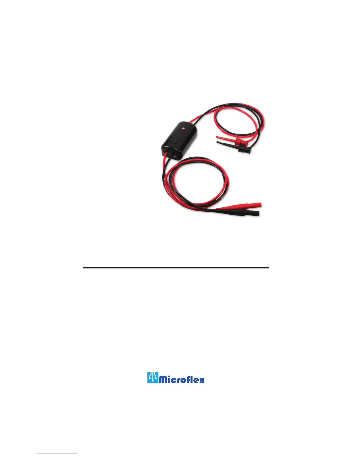
The Field Tools 24V Supply provides portable power to loop powered devices.
It is a fully contained power source that takes the low voltage from three “AAA”
alkaline batteries and increases it to a highly filtered 24 volts DC. Using batteries
for the power source eliminates isolation concerns as well as the need for a
power connection to AC or a USB port. The voltage conversion is done using
a high efficiency switching DC-DC converter to maximize battery life. Simply
connect the two mini-clips to the power input of your loop powered device.
A push-button is used to enable or disable the 24 volts while a status LED
indicates the active operating mode. An internal 250 ohm loop resistor, HART
protocol modem clip points, and current meter leads with standard banana jacks
make the 24V Supply a complete loop transmitter power solution.
101-0028
24V Supply
Field Tools
Operation &
Specifications
Manual

2
Safety Considerations
• Never apply more than 30 volts between any two terminals or leads.
• Never operate with the battery cover and cover screws removed or loose.
• Do not use if the leads become damaged.
• Disconnect all connections before removing the battery cover.
• Do not operate around explosive gas, vapor, or dust.
• Contact Microflex, LLC for servicing or repairs.
Warning
To prevent loss or injury only use the 24V Supply as specified in the manual.
Replacing or Installing Batteries
1. Loosen and remove the two cover screws and cover to access the battery
holder.
2. Remove and replace all three “AAA” alkaline batteries.
3. Replace the cover and screws. Do not over-tighten the screws to prevent
damage to the 24V Supply enclosure.
For best performance the batteries should be replaced as soon as the low battery
indication is noticed (flashing status LED while connected).
Always disconnect all leads and connections to the 24V Supply before
removing the battery cover.
• Highly filtered 24 volt power source for loop devices
• Up to 30mA capacity, perfect for 4-20mA transmitters
• Battery power eliminates galvanic isolation concerns
• Includes an internal 250 ohm loop resistor to allow for HART protocol
• HART modem mini-grabber clip points for easy modem connection to the loop
• Mini-clips for easy connection to the loop device power terminals
• All connection leads included - no need for extra test leads or alligator clips
• Long battery life, greater than 6 hours continuous at 12mA load
• Status LED indicates when batteries are getting low
• Able to maintain output even with weak batteries to maximize battery life
• Uses easy to find low cost standard “AAA” alkaline batteries
• Short circuit protection disconnects the output if shorted or over-current detected
• Compact durable enclosure stands up to rugged field use
24V Supply Features
3
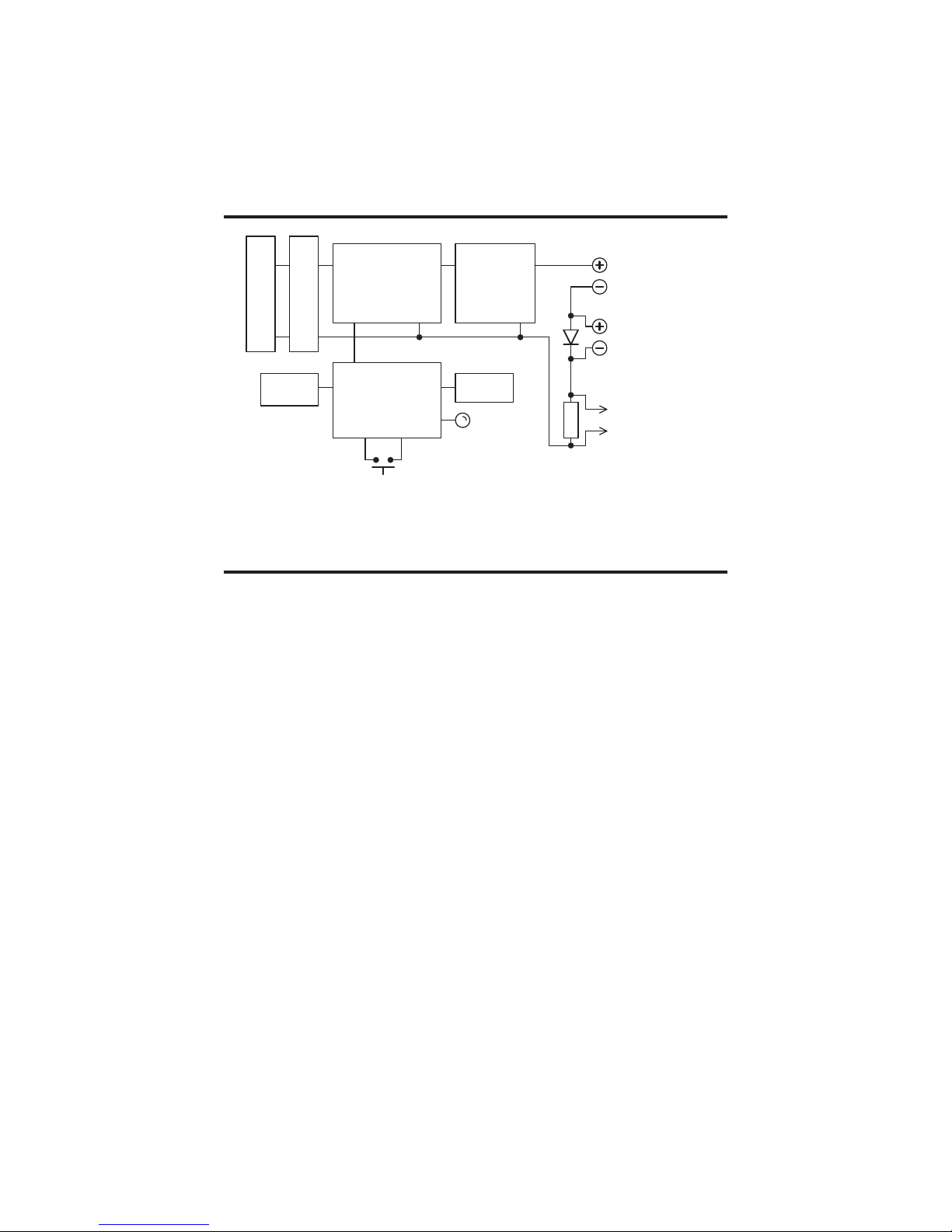
24V Supply Block Diagram
Figure 1: Block Diagram
REVERSE BATTERY
PROTECTION
3 X "AAA" BATTERY
DC-DC CONVERTER
BATTERY
MONITOR
HIGH EFFICIENCY FILTER
24 VOLT
TRANSMITTER POWER
SUPPLY LEADS
MILLIAMP METER
TEST LEADS
HART PROTOCOL
MODEM CONNECTIONS
CONTROLLER
CURRENT
MONITOR
STATUS LED
CONNECT / OFF
BUTTON
250Ω
Connecting to a Loop Device
The Field Tools 24V Supply is a fully contained power source for loop powered
transmitters. Internal batteries eliminate the need for external connections to
AC power or USB ports as a power source while providing complete galvanic
isolation.
Connect the red clip to power or loop (+) and the black lead to power or loop (-)
on your transmitter. See Figure 2 Device Connections for details.The transmitter
can be powered with or without the milliamp meter connected. The power loop
is not opened when the meter is removed or not attached.
With the 24V Supply clips attached to the transmitter, press the 24V Supply con-
nect button to enable power to the transmitter. The status LED will be ON while
the 24V Supply output is active. If the LED is not ON solid while active, refer
to Status LED Operation in this manual.
To remove power from the transmitter press the connect button. The LED will
be OFF while the 24V Supply output is inactive.
The 24V Supply includes a 250 ohm loop resistor that will drop a portion of
the available 24 volts. The voltage dropped across the resistor depends on the
current requirements for the loop transmitter. Open circuit voltage, with no
transmitter attached, is 24 volts +/- 2%.
4
Measuring Loop Current
The 24V Supply includes leads to simplify connection to a DC current meter
for loop current measurements. The current meter leads have safety insulated
banana plugs that can be plugged directly into a standard current meter. An
internal diode allows the meter to be connected or disconnected without inter-
rupting the loop supply or opening the loop. See Figure 2 Device Connections
for details.
HART Protocol Modem Connections
A HART modem or HART communicator can be connected to the 24V Supply
loop using the two loop-terminals provided next to the current meter leads. The
loop terminals allow standard HART modem mini-clips to be easily connected
across an internal 250 ohm loop resistor.
MINMAX RANGE
REL Hz %
AutoHOLD
PeakMIN MAX
4½DIGITS
1Second
˚
C/
˚
F
OFF
mA
A
mV
V
VA
A
mA
COM V
400mA
FUSED
10AMAX
FUSED
A
LOLO
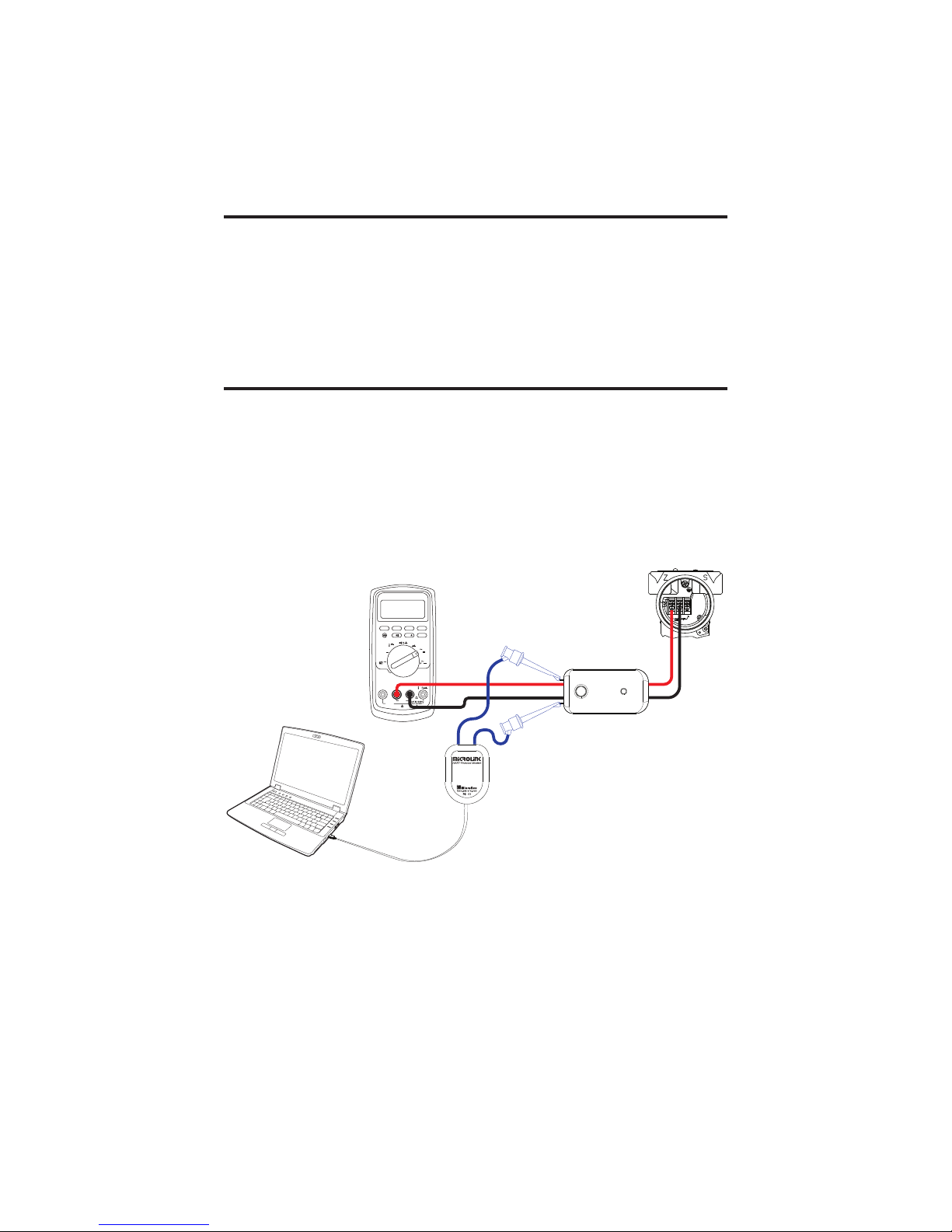
Connect a milliamp meter
to the shielded banana
jack leads to monitor loop
current.
Removing the current
meter does not open the
loop.
For calibrating HART devices a HART
protocol modem or calibrator can be
attached across the internal 250Ωloop
resistor by clipping on as shown.
Connect the red mini-clip to the
transmitter (+) supply terminal.
Connect the black mini-clip
to the transmitter (-) supply
terminal.
Figure 2: Device connections
Milliamp Meter (optional)
Loop Transmitter

5
Status LED Operation
The Status LED provides quick feedback of the 24V Supply operating mode.
The LED can indicate when the battery is getting low and needs to be replaced
or when the output is shorted or connected to a load that exceeds the 30 milli-
amp maximum.
LED Off
If the status LED is off, the 24V Supply is not connected or not supplying power
to the output. If the LED remains off after the button is pressed, the internal
batteries need to be replaced. For details refer to the section on “Replacing Bat-
teries” in this manual.
LED On
When the 24V Supply is active and providing power to the output, and no fault
conditions are detected, the LED will be ON solid.
LED Fast Flash then Off
If an over-current condition is detected, more than 30mA or shorted, the output
will be disconnected and the led will flash for about 2 seconds. Remove the
overload or shorted condition and press the connect button to restore the active
output.
LED Slow Flash
A slow flashing status LED indicates that the output is connected but the
internal supply is low and the batteries need to be replaced. The 24 volt output
may not be fully regulated when the batteries are low. Replace the internal three
“AAA” alkaline batteries if they are low to ensure a stable power output. For
details refer to “Replacing Batteries” in this manual.
Auto Power Off
To help reserve battery life the 24V Supply will automatically disconnect and
power down after 30 minutes. Press the connect button to re-connect.

Specifications
Output
Open Loop Voltage ....................................................................24V +/- 2%
Load Regulation.................................................................................0.25%
Noise............................................................Less than 50mV P-P @ 20mA
Current ........................................................................................30mA max
Short Circuit / Overload Protection ........ Auto-disconnect if load is > 30mA
Leads ............................................3’ (1 meter) high flexibility test lead wire
Termination .....................................................................Mini-Grabber clips
Current Meter Leads
Leads ................................. 2 Feet (0.6 Meter) high flexibility test lead wire
Termination ................................Shielded banana plugs, Red (+), Black (-)
HART Protocol Support
Connection Type ............................. clip loop terminals (.087” x .055” hole)
250ΩLoop Resistor ........................................................Included internally
Battery
Type ........................................................................3 x 1.5V “AAA” alkaline
Operating Life ..................................................... > 6 hours with 12mA load
Battery Supply Range (DO NOT USE 3V CELLS)...................2.0V to 5.5V
Low Battery Indicator ........Status LED will flash slow while output is active
Low Battery Level .............................................................................. 2.49V
Auto Off duration........................................................................ 30 minutes
Enclosure
Molded ABS Plastic
Weight (including leads and batteries).......................................... 6 ounces
Enclosure Dimensions .................................................1.70” x 3.25” x 1.13”
Environmental
Operating Temperature ............................... -30ºC to 50ºC (-22ºF to 122ºF)
Storage Temperature .................................. -40ºC to 70ºC (-40ºF to 158ºF)
Humidity ............................................................0 to 95% (non-condensing)
6

7
1.125
28.58 mm
3.250
82.55 mm
1.700
43.18 mm
(-) CURRENT METER
+ CURRENT METER
36"
915 mm 24"
610 mm
BATTERY COVER
SCREWS
CONNECT BUTTON
STATUS LED
HART CLIP
(-) LOOP POWER
+ LOOP POWER
Dimensions
Figure 3: Dimensions

Limited Warranty
Microflex, LLC warrants this unit against defects in materials and
workmanship for a period of one year from the date of shipment. Microflex,
LLC will, at its option, repair or replace equipment that proves to be defective
during the warranty period. This warranty includes parts and labor.
A Return Authorization (RA) number must be obtained from the factory
and clearly marked on the outside of the package before equipment will be
accepted for warranty work.
Microflex, LLC believes that the information in this manual is accurate. In the
event that a typographical or technical error exist, Microflex, LLC reserves
the right to make changes without prior notice to holders of this edition.
The reader should consult Microflex, LLC if any errors are suspected. In no
event should Microflex be liable for any damages arising out of or related to
this document or the information contained in it.
EXCEPT AS SPECIFIED HEREIN, MICROFLEX, LLC MAKES
NO WARRANTIES OR MERCHANTABILITY OR FITNESS FOR
A PARTICULAR PURPOSE. CUSTOMER’S RIGHT TO RECOVER
DAMAGES CAUSED BY FAULT OR NEGLIGENCE ON THE PART
OF MICROFLEX, LLC SHALL BE LIMITED TO THE AMOUNT
THERETOFORE PAID BY THE CUSTOMER. MICROFLEX, LLC
WILL NOT BE LIABLE FOR DAMAGES RESULTING FROM
LOSS OF DATA, PROFITS, USE OF PRODUCTS, OR INCIDENTAL
OR CONSEQUENTIAL DAMAGES, EVEN IF ADVISED OF THE
POSSIBILITIES THEREOF. This limitation of the liability of Microflex will
apply regardless of the form of action, whether in contract or tort, including
negligence. Any action against Microflex, LLC must be brought within
one year after the cause of action accrues. The warranty provided herein
does not cover damages, defects, malfunctions, or service failures caused by
owners failure to follow Microflex’s installation, operation, or maintenance
instructions; owners modification of the product; owner’s abuse, misuse, or
negligent acts; and power failure or surges, fire, flood, accident, actions of
third parties, or other events outside reasonable control.
Microflex, LLC
2202 Red Bird Lane
Brookshire, Texas 77423
USA
Phone 281-855-9639
Fax 832-422-4391
www.microflx.com
Table of contents
Popular Power Supply manuals by other brands


Thermal Dynamics
Thermal Dynamics 38 Cutmaster instruction manual

Nortel
Nortel Passport 8600 Series Installation

Guntermann & Drunck
Guntermann & Drunck MultiPower-6-NT installation guide

Camtec
Camtec CPS-EC480 manual

GW Instek
GW Instek PSW Series Programming manual

CARLO GAVAZZI
CARLO GAVAZZI SPDE 1202R Series manual


