Thermal Dynamics 38 Cutmaster User manual
December 9, 2002 Manual No. 0-2879
Instruction Manual
PLASMA CUTTING
POWER SUPPLY
Drag-Gun™ 38
Used With PCH-42 RPT SureLok™Torch
A-02145
23x4334REVA
MADEINTHEUSA
TM
23x4334REVA
MADEINTHEUSA
TM
CURRENT
1229
20
ACGASDC
OVER
TEMP
WORK
TORCH
®
R
MADEINT HEUSA
TM
0.1in(2.5mm)Examinefor
elongated,cratered,or
oversizedorifice.
Electrode9-6506
GasDistributor9-6507
Tip9-6501
ShieldCup9-6003
PartDescriptionCatalogNo.
REPLACEMENT
TORCHPARTS
Checktheelectrodeandtipforexcessivewear.
Replaceelectrodeifwornbackmorethan0.1"
(2.5mm).Checktiporificeforout-of-roundwear.
TorchHeadAssembly
ShieldCup
Gas
DistributorTip
Electrode
ProperAssemblyofTorchHeadComponents


Record the following information for Warranty purposes:
Where Purchased: _______________________________________
Purchase Date: _______________________________________
Power Supply Serial #: _______________________________________
Torch Serial #: _______________________________________
WARNINGS
Read and understand this entire Manual and your employer’s safety practices before installing, oper-
ating, or servicing the equipment.
While the information contained in this Manual represents the Manufacturer's best judgement, the
Manufacturer assumes no liability for its use.
Plasma Cutting Power Supply
Drag-Gun™ 38
Instruction Manual Number 0-2879
Published by:
Thermal Dynamics Corporation
82 Benning Street
West Lebanon, New Hampshire, USA 03784
(603) 298-5711
www.thermadyne.com
Copyright 2001 by
Thermal Dynamics Corporation
All rights reserved.
Reproduction of this work, in whole or in part, without written per-
mission of the publisher is prohibited.
The publisher does not assume and hereby disclaims any liability to
any party for any loss or damage caused by any error or omission in
this Manual, whether such error results from negligence, accident, or
any other cause.
Printed in the United States of America
Publication Date: December 9, 2002

TABLE OF CONTENTS
SECTION 1:
GENERAL INFORMATION ............................................................................................... 1-1
1.01 Notes, Cautions andWarnings ..................................................................... 1-1
1.02 Important Safety Precautions ....................................................................... 1-1
1.03 Publications.................................................................................................. 1-2
1.04 Note, Attention et Avertissement .................................................................. 1-3
1.05 Precautions De Securite Importantes........................................................... 1-3
1.06 Documents De Reference ............................................................................ 1-5
1.07 Declaration of Conformity............................................................................. 1-7
1.08 Statement ofWarranty.................................................................................. 1-8
SECTION 2:
INTRODUCTION & DESCRIPTION.................................................................................. 2-1
2.01 Scope of Manual .......................................................................................... 2-1
2.02 General Description ..................................................................................... 2-1
2.03 Specifications & Design Features................................................................. 2-1
SECTION 3:
INSTALLATION PROCEDURES ....................................................................................... 3-1
3.01 Introduction .................................................................................................. 3-1
3.02 Site Location ................................................................................................ 3-1
3.03 Unpacking .................................................................................................... 3-1
3.04 HandleInstallation........................................................................................ 3-1
3.05 Electrical Connection ................................................................................... 3-1
3.06 Torch Connection ......................................................................................... 3-2
SECTION 4:
OPERATION ..................................................................................................................... 4-1
4.01 Introduction .................................................................................................. 4-1
4.02 Operating Controls ....................................................................................... 4-1
4.03 Getting Started............................................................................................. 4-1
4.04 Operating the System .................................................................................. 4-2
4.05 Recommended Cutting Speeds.................................................................... 4-3
SECTION 5:
SERVICE ......................................................................................................................... 5-1
5.01 Introduction .................................................................................................. 5-1
5.02 GeneralMaintenance ................................................................................... 5-1
5.03 Common Operating Faults ........................................................................... 5-1
5.04 TroubleshootingGuides................................................................................ 5-2
5.05 BasicTroubleshooting Guide ........................................................................ 5-2
5.06 AdvancedTroubleshooting Guide ................................................................. 5-3
5.07 Troubleshooting Flow Charts ........................................................................ 5-3
5.08 Test Procedures ......................................................................................... 5-10
5.09 Power Supply Component Replacement Procedures................................. 5-15
5.10 Torch and Leads Replacement Procedure ................................................. 5-20

TABLE OF CONTENTS (continued)
SECTION 6:
PARTS LISTS.................................................................................................................... 6-1
6.01 Introduction .................................................................................................. 6-1
6.02 Ordering Information .................................................................................... 6-1
6.03 Power Supply Replacement Parts ................................................................ 6-2
6.04 Rear Panel Replacement Parts .................................................................... 6-4
6.05 Complete Assembly Replacement ............................................................... 6-6
APPENDIX 1: SEQUENCE OF OPERATION BLOCK DIAGRAM.............................................A-1
APPENDIX 2: ROUTINE MAINTENANCE SCHEDULE............................................................A-2
APPENDIX 3: RECOMMENDED CUTTING SPEEDS..............................................................A-3
APPENDIX 4: NON-CE SYSTEM SCHEMATIC........................................................................A-4
APPENDIX 5: CE & AUSTRALIA SYSTEM SCHEMATIC.........................................................A-6


Date: November 15, 2001 1-1 GENERAL INFORMATION
SECTION 1:
GENERAL INFORMATION
1.01 Notes, Cautions and Warnings
Throughout this manual, notes, cautions, and warnings
areused to highlight important information. These high-
lights are categorized as follows:
NOTE
An operation, procedure, or background informa-
tion which requires additional emphasis or is help-
ful in efficient operation of the system.
CAUTION
A procedure which, if not properly followed, may
cause damage to the equipment.
WARNING
A procedure which, if not properly followed, may
cause injury to the operator or others in the oper-
ating area.
1.02 Important Safety Precautions
WARNINGS
OPERATION AND MAINTENANCE OF
PLASMA ARC EQUIPMENT CAN BE DAN-
GEROUS AND HAZARDOUS TO YOUR
HEALTH.
Plasma arc cutting produces intense electric and
magnetic emissions that may interfere with the
proper function of cardiac pacemakers, hearing
aids, or other electronic health equipment. Per-
sons who work near plasma arc cutting applica-
tions should consult their medical health profes-
sional and the manufacturer of the health
equipment to determine whether a hazard exists.
To prevent possible injury, read, understand and
follow all warnings, safety precautions and in-
structionsbeforeusing the equipment. Call 1-603-
298-5711 or your local distributor if you have any
questions.
GASES AND FUMES
Gases and fumes produced during the plasma cutting
process can be dangerous and hazardous to your health.
• Keep all fumes and gases from the breathing area.
Keep your head out of the welding fume plume.
• Use an air-supplied respirator if ventilation is not
adequate to remove all fumes and gases.
• The kinds of fumes and gases from the plasma arc
depend on the kind of metal being used, coatings
onthe metal, and the differentprocesses. You must
be very careful when cutting or welding any met-
als which may contain one or more of the follow-
ing:
Antimony Chromium Mercury
Arsenic Cobalt Nickel
Barium Copper Selenium
Beryllium Lead Silver
Cadmium Manganese Vanadium
• Always read the Material Safety Data Sheets
(MSDS) that should be supplied with the material
you are using. These MSDSs will give you the in-
formationregardingthekindand amount of fumes
and gases that may be dangerous to your health.
• For information on how to test for fumes and gases
inyourworkplace, referto item 1inSubsection1.03,
Publications in this manual.
• Usespecialequipment, such as water or downdraft
cutting tables, to capture fumes and gases.
• Do not use the plasma torch in an area where com-
bustible or explosive gases or materials are located.
• Phosgene, a toxic gas, is generated from the vapors
of chlorinated solvents and cleansers. Remove all
sources of these vapors.
• This product, when used for welding or cutting,
produces fumes or gases which contain chemicals
known to the State of California to cause birth de-
fects and, in some cases, cancer. (California Health
& Safety Code Sec. 25249.5 et seq.)
ELECTRIC SHOCK
Electric Shock can injure or kill. The plasma arc process
uses and produces high voltage electrical energy. This
electric energy can cause severe or fatal shock to the op-
erator or others in the workplace.
• Never touch any parts that are electrically “live”
or “hot.”
GENERAL INFORMATION 1-2 Date: November 15, 2001
• Wear dry gloves and clothing. Insulate yourself
from the work piece or other parts of the welding
circuit.
• Repair or replace all worn or damaged parts.
• Extra care must be taken when the workplace is
moist or damp.
• Install and maintain equipment according to NEC
code, refer to item 9 in Subsection 1.03, Publica-
tions.
• Disconnect power source before performing any
service or repairs.
• Read and follow all the instructions in the Operat-
ing Manual.
FIRE AND EXPLOSION
Fire and explosion can be caused by hot slag, sparks, or
the plasma arc.
• Be sure there is no combustible or flammable ma-
terial in the workplace. Any material that cannot
be removed must be protected.
• Ventilate all flammable or explosive vapors from
the workplace.
• Do not cut or weld on containers that may have
held combustibles.
• Provideafirewatch whenworkingin an areawhere
fire hazards may exist.
• Hydrogen gas may be formed and trapped under
aluminum workpieces when they are cut under-
water or while using a water table. DO NOT cut
aluminum alloys underwater or on a water table
unless the hydrogen gas can be eliminated or dis-
sipated. Trapped hydrogen gas that is ignited will
cause an explosion.
NOISE
Noisecancausepermanenthearingloss. Plasmaarcpro-
cesses can cause noise levels to exceed safe limits. You
must protect your ears from loud noise to prevent per-
manent loss of hearing.
• To protect your hearing from loud noise, wear pro-
tective ear plugs and/or ear muffs. Protect others
in the workplace.
• Noiselevelsshould be measuredto be surethedeci-
bels (sound) do not exceed safe levels.
• For information on how to test for noise, see item 1
in Subsection 1.03, Publications, in this manual.
PLASMAARC RAYS
PlasmaArcRayscaninjureyour eyes andburnyourskin.
The plasma arc process produces very bright ultra violet
and infra red light. These arc rays will damage your
eyesandburn your skin if youarenotproperlyprotected.
• To protect your eyes, always wear a welding hel-
metorshield. Alsoalwayswearsafetyglasseswith
side shields, goggles or other protective eye wear.
• Wear welding gloves and suitable clothing to pro-
tect your skin from the arc rays and sparks.
• Keep helmet and safety glasses in good condition.
Replace lenses when cracked, chipped or dirty.
• Protect others in the work area from the arc rays.
Use protective booths, screens or shields.
• Use the shade of lens as suggested in the following
per ANSI/ASC Z49.1:
Minimum Protective Suggested
Arc Current Shade No. Shade No.
Less Than 300* 8 9
300 - 400* 9 12
400 - 800* 10 14
* Thesevaluesapplywherethe actual arcisclearly
seen. Experience has shown that lighter filters
may be used when the arc is hidden by the work-
piece.
1.03 Publications
Refer to the following standards or their latest revisions
for more information:
1. OSHA, SAFETYAND HEALTH STANDARDS, 29CFR
1910, obtainable from the Superintendent of Docu-
ments, U.S. Government Printing Office, Washington,
D.C. 20402
2. ANSI Standard Z49.1, SAFETY IN WELDING AND
CUTTING, obtainable from theAmerican Welding So-
ciety, 550 N.W. LeJeune Rd, Miami, FL 33126
3. NIOSH, SAFETY AND HEALTH IN ARC WELDING
AND GAS WELDING AND CUTTING, obtainable
from the Superintendent of Documents, U.S. Govern-
ment Printing Office, Washington, D.C. 20402
4. ANSI Standard Z87.1, SAFE PRACTICES FOR OCCU-
PATIONAND EDUCATIONALEYEAND FACE PRO-
TECTION, obtainable from American National Stan-
dards Institute, 1430 Broadway, New York, NY 10018
5. ANSI Standard Z41.1, STANDARD FOR MEN’S
SAFETY-TOE FOOTWEAR,obtainable fromtheAmeri-
can National Standards Institute, 1430 Broadway, New
York, NY 10018

Date: November 15, 2001 1-3 GENERAL INFORMATION
6. ANSI StandardZ49.2, FIREPREVENTION IN THEUSE
OF CUTTING AND WELDING PROCESSES, obtain-
able from American National Standards Institute, 1430
Broadway, New York, NY 10018
7. AWS StandardA6.0, WELDINGAND CUTTING CON-
TAINERS WHICH HAVE HELD COMBUSTIBLES, ob-
tainable from American Welding Society, 550 N.W.
LeJeune Rd, Miami, FL 33126
8. NFPA Standard 51, OXYGEN-FUEL GAS SYSTEMS
FOR WELDING, CUTTING AND ALLIED PRO-
CESSES, obtainable from the National Fire Protection
Association, Batterymarch Park, Quincy, MA 02269
9. NFPA Standard 70, NATIONAL ELECTRICAL CODE,
obtainable from the National Fire Protection Associa-
tion, Batterymarch Park, Quincy, MA 02269
10. NFPAStandard 51B, CUTTINGAND WELDING PRO-
CESSES, obtainable from the National Fire Protection
Association, Batterymarch Park, Quincy, MA 02269
11. CGA Pamphlet P-1, SAFE HANDLING OF COM-
PRESSED GASES IN CYLINDERS, obtainable from the
Compressed Gas Association, 1235 Jefferson Davis
Highway, Suite 501, Arlington, VA 22202
12. CSAStandard W117.2, CODE FOR SAFETY IN WELD-
ING AND CUTTING, obtainable from the Canadian
Standards Association, Standards Sales, 178 Rexdale
Boulevard, Rexdale, Ontario, Canada M9W 1R3
13. NWSA booklet, WELDING SAFETY BIBLIOGRAPHY
obtainable from the National Welding Supply Associa-
tion, 1900 Arch Street, Philadelphia, PA 19103
14. American WeldingSociety StandardAWSF4.1, RECOM-
MENDED SAFE PRACTICES FOR THE PREPARA-
TION FOR WELDINGAND CUTTING OF CONTAIN-
ERSAND PIPING THAT HAVE HELD HAZARDOUS
SUBSTANCES, obtainable from theAmerican Welding
Society, 550 N.W. LeJeune Rd, Miami, FL 33126
15. ANSI Standard Z88.2, PRACTICE FOR RESPIRATORY
PROTECTION, obtainable from American National
Standards Institute, 1430 Broadway, New York, NY
10018
1.04 Note, Attention et
Avertissement
Dans ce manuel, les mots “note,” “attention,” et
“avertissement” sont utilisés pour mettre en relief des
informations à caractère important. Ces mises en relief
sont classifiées comme suit :
NOTE
Toute opération, procédure ou renseignement
général sur lequel il importe d’insister davantage
ou qui contribue à l’efficacité de fonctionnement
du système.
ATTENTION
Toute procédure pouvant résulter
l’endommagement du matériel en cas de non-
respect de la procédure en question.
AVERTISSEMENT
Toute procédure pouvant provoquer des blessures
de l’opérateur ou des autres personnes se trouvant
dans la zone de travail en cas de non-respect de la
procédure en question.
1.05 Precautions De Securite
Importantes
AVERTISSEMENTS
L’OPÉRATION ET LA MAINTENANCE DU
MATÉRIEL DE SOUDAGE À L’ARC AU JET
DE PLASMA PEUVENT PRÉSENTER DES
RISQUES ET DES DANGERS DE SANTÉ.
Coupantàl’arc au jetdeplasma produitde l’énergie
électrique haute tension et des émissions
magnétique qui peuvent interférer la fonction
propre d’un “pacemaker” cardiaque, les appareils
auditif, ou autre matériel de santé electronique.
Ceux qui travail près d’une application à l’arc au
jet de plasma devrait consulter leur membre
professionel de médication et le manufacturier de
matériel de santé pour déterminer s’il existe des
risques de santé.
Il faut communiquer aux opérateurs et au person-
nel TOUS les dangers possibles. Afin d’éviter les
blessures possibles, lisez, comprenez et suivez tous
lesavertissements, toutes les précautionsdesécurité
et toutes les consignes avant d’utiliser le matériel.
Composez le + 603-298-5711 ou votre distributeur
local si vous avez des questions.
FUMÉE et GAZ
La fumée et les gaz produits par le procédé de jet de
plasma peuvent présenter des risques et des dangers de
santé.
GENERAL INFORMATION 1-4 Date: November 15, 2001
• Eloignez toute fumée et gaz de votre zone de respira-
tion. Gardez votre tête hors de la plume de fumée
provenant du chalumeau.
• Utilisez un appareil respiratoire à alimentation en air
sil’aérationfournienepermetpasd’éliminerlafumée
et les gaz.
• Les sortes de gaz et de fumée provenant de l’arc de
plasma dépendent du genre de métal utilisé, des
revêtements se trouvant sur le métal et des différents
procédés. Vous devez prendre soin lorsque vous
coupez ou soudez tout métal pouvant contenir un ou
plusieurs des éléments suivants:
antimoine cadmium mercure
argent chrome nickel
arsenic cobalt plomb
baryum cuivre sélénium
béryllium manganèse vanadium
• Lisez toujours les fiches de données sur la sécurité
des matières (sigle américain “MSDS”); celles-ci
devraient être fournies avec le matériel que vous
utilisez. Les MSDS contiennent des renseignements
quant à la quantité et la nature de la fumée et des gaz
pouvant poser des dangers de santé.
• Pour des informations sur la manière de tester la
fumée et les gaz de votre lieu de travail, consultez
l’article 1 et les documents cités à la page 5.
• Utilisez un équipement spécial tel que des tables de
coupe à débit d’eau ou à courant descendant pour
capter la fumée et les gaz.
• N’utilisez pas le chalumeau au jet de plasma dans une
zone où se trouvent des matières ou des gaz combus-
tibles ou explosifs.
• Le phosgène, un gaz toxique, est généré par la fumée
provenant des solvants et des produits de nettoyage
chlorés. Eliminez toute source de telle fumée.
• Ce produit, dans le procéder de soudage et de coupe,
produit de la fumée ou des gaz pouvant contenir des
éléments reconnu dans L’état de la Californie, qui
peuvent causer des défauts de naissance et le cancer.
(La sécurité de santé en Californie et la code sécurité
Sec. 25249.5 et seq.)
CHOC ELECTRIQUE
Les chocs électriques peuvent blesser ou même tuer. Le
procédé au jet de plasma requiert et produit de l’énergie
électrique haute tension. Cette énergie électrique peut
produiredes chocs graves, voiremortels,pour l’opérateur
et les autres personnes sur le lieu de travail.
• Netouchezjamaisune pièce “sous tension” ou “vive”;
portez des gants et des vêtements secs. Isolez-vous
de la pièce de travail ou des autres parties du circuit
de soudage.
• Réparez ou remplacez toute pièce usée ou
endommagée.
• Prenez des soins particuliers lorsque la zone de tra-
vail est humide ou moite.
• Montez et maintenez le matériel conformément au
Code électrique national des Etats-Unis. (Voir la page
5, article 9.)
• Débranchez l’alimentation électrique avant tout tra-
vail d’entretien ou de réparation.
• Lisez et respectez toutes les consignes du Manuel de
consignes.
INCENDIE ET EXPLOSION
Lesincendies et les explosionspeuventrésulter desscories
chaudes, des étincelles ou de l’arc de plasma. Le procédé
à l’arc de plasma produit du métal, des étincelles, des
scories chaudes pouvant mettre le feu aux matières com-
bustibles ou provoquer l’explosion de fumées
inflammables.
• Soyez certain qu’aucune matière combustible ou in-
flammable ne se trouve sur le lieu de travail. Protégez
toute telle matière qu’il est impossible de retirer de la
zone de travail.
• Procurez une bonne aération de toutes les fumées
inflammables ou explosives.
• Ne coupez pas et ne soudez pas les conteneurs ayant
pu renfermer des matières combustibles.
• Prévoyezune veilled’incendielorsde tout travaildans
une zone présentant des dangers d’incendie.
• Le gas hydrogène peut se former ou s’accumuler sous
les pièces de travail en aluminium lorsqu’elles sont
coupées sous l’eau ou sur une table d’eau. NE PAS
couper les alliages en aluminium sous l’eau ou sur
une table d’eau à moins que le gas hydrogène peut
s’échapperousedissiper. Le gas hydrogèneaccumulé
explosera si enflammé.
RAYONS D’ARC DE PLASMA
Les rayons provenant de l’arc de plasma peuvent blesser
vos yeux et brûler votre peau. Le procédé à l’arc de
plasma produit une lumière infra-rouge et des rayons

Date: November 15, 2001 1-5 GENERAL INFORMATION
ultra-violets très forts. Ces rayons d’arc nuiront à vos
yeux et brûleront votre peau si vous ne vous protégez
pas correctement.
• Pour protéger vos yeux, portez toujours un casque ou
un écran de soudeur. Portez toujours des lunettes de
sécurité munies de parois latérales ou des lunettes de
protection ou une autre sorte de protection oculaire.
• Portezdesgants de soudeur et un vêtementprotecteur
approprié pour protéger votre peau contre les
étincelles et les rayons de l’arc.
• Maintenez votre casque et vos lunettes de protection
en bon état. Remplacez toute lentille sale ou
comportant fissure ou rognure.
• Protégez les autres personnes se trouvant sur la zone
de travail contre les rayons de l’arc en fournissant des
cabines ou des écrans de protection.
• Utilisez la nuance de lentille qui est suggèrée dans le
recommendation qui suivent ANSI/ASC Z49.1:
Nuance Minimum Nuance Suggerée
Courant Arc Protective Numéro Numéro
Moins de 300* 8 9
300 - 400* 9 12
400 - 800* 10 14
*Cesvaleurs s’appliquent ou l’arcactuel est observé
clairement. L’experience a démontrer que les filtres
moins foncés peuvent être utilisés quand l’arc est
caché par moiceau de travail.
BRUIT
Le bruit peut provoquer une perte permanente de l’ouïe.
Les procédés de soudage à l’arc de plasma peuvent
provoquer des niveaux sonores supérieurs aux limites
normalement acceptables. Vous dú4ez vous protéger les
oreilles contre les bruits forts afin d’éviter une perte
permanente de l’ouïe.
• Pour protéger votre ouïe contre les bruits forts, portez
des tampons protecteurs et/ou des protections
auriculaires. Protégezégalement les autrespersonnes
se trouvant sur le lieu de travail.
• Il faut mesurer les niveaux sonores afin d’assurer que
les décibels (le bruit) ne dépassent pas les niveaux
sûrs.
• Pour des renseignements sur la manière de tester le
bruit, consultez l’article 1, page 5.
1.06 Documents De Reference
Consultez les normes suivantes ou les révisions les plus
récentes ayant été faites à celles-ci pour de plus amples
renseignements :
1. OSHA, NORMES DE SÉCURITÉ DU TRAVAILETDE
PROTECTION DE LA SANTÉ, 29CFR 1910,
disponible auprès du Superintendent of Documents,
U.S. Government Printing Office, Washington, D.C.
20402
2. Norme ANSI Z49.1, LA SÉCURITÉ DES
OPÉRATIONS DE COUPE ET DE SOUDAGE,
disponible auprès de la Société Américaine de
Soudage (American Welding Society), 550 N.W.
LeJeune Rd., Miami, FL 33126
3. NIOSH, LA SÉCURITÉ ET LA SANTÉ LORS DES
OPÉRATIONS DE COUPE ET DE SOUDAGE À
L’ARC ET AU GAZ, disponible auprès du Superin-
tendent of Documents, U.S. Government Printing
Office, Washington, D.C. 20402
4. Norme ANSI Z87.1, PRATIQUES SURES POUR LA
PROTECTION DES YEUX ET DU VISAGEAU TRA-
VAILET DANS LES ECOLES, disponible de l’Institut
Américain des Normes Nationales (American Na-
tionalStandardsInstitute), 1430 Broadway,NewYork,
NY 10018
5. Norme ANSI Z41.1, NORMES POUR LES
CHAUSSURES PROTECTRICES, disponible auprès
de l’American National Standards Institute, 1430
Broadway, New York, NY 10018
6. NormeANSI Z49.2, PRÉVENTION DES INCENDIES
LORS DE L’EMPLOI DE PROCÉDÉS DE COUPE ET
DE SOUDAGE, disponible auprès de l’American Na-
tional Standards Institute, 1430 Broadway, New York,
NY 10018
7. NormeA6.0 de l’AssociationAméricaine du Soudage
(AWS), LE SOUDAGE ET LA COUPE DE
CONTENEURSAYANT RENFERMÉ DESPRODUITS
COMBUSTIBLES, disponible auprès de la American
Welding Society, 550 N.W. LeJeune Rd., Miami, FL
33126
8. Norme 51 de l’Association Américaine pour la Pro-
tection contre les Incendies (NFPA), LES SYSTEMES
À GAZ AVEC ALIMENTATION EN OXYGENE
POUR LE SOUDAGE, LA COUPE ET LES
PROCÉDÉS ASSOCIÉS, disponible auprès de la Na-
tional Fire ProtectionAssociation, Batterymarch Park,
Quincy, MA02269

GENERAL INFORMATION 1-6 Date: November 15, 2001
9. Norme 70 de la NFPA, CODE ELECTRIQUE NA-
TIONAL, disponible auprès de la National Fire Pro-
tectionAssociation, BatterymarchPark, Quincy, MA
02269
10. Norme 51B de la NFPA, LES PROCÉDÉS DE
COUPE ET DE SOUDAGE, disponible auprès de la
National Fire ProtectionAssociation, Batterymarch
Park, Quincy, MA02269
11. Brochure GCA P-1, LA MANIPULATION SANS
RISQUE DES GAZ COMPRIMÉS EN CYLINDRES,
disponible auprès de l’Association des Gaz
Comprimés (Compressed Gas Association), 1235
Jefferson Davis Highway, Suite 501, Arlington, VA
22202
12. Norme CSA W117.2, CODE DE SÉCURITÉ POUR
LE SOUDAGE ET LA COUPE, disponible auprès
de l’Association des Normes Canadiennes, Stan-
dards Sales, 178 Rexdale Boulevard, Rexdale,
Ontario, Canada, M9W 1R3
13.Livret NWSA, BIBLIOGRAPHIE SUR LA
SÉCURITÉ DU SOUDAGE, disponible auprès de
l’Association Nationale de Fournitures de Soudage
(National Welding Supply Association), 1900 Arch
Street, Philadelphia, PA 19103
14. Norme AWSF4.1 de l’Association Américaine de
Soudage, RECOMMANDATIONS DE PRATIQUES
SURES POUR LAPRÉPARATION ÀLACOUPE ET
AU SOUDAGE DE CONTENEURS ET TUYAUX
AYANT RENFERMÉ DES PRODUITS
DANGEREUX , disponible auprès de la American
Welding Society, 550 N.W. LeJeune Rd., Miami, FL
33126
15. NormeANSI Z88.2, PRATIQUES DE PROTECTION
RESPIRATOIRE, disponible auprès de l’American
National Standards Institute, 1430 Broadway, New
York, NY 10018

Date: November 15, 2001 1-7 GENERAL INFORMATION
1.07 Declaration of Conformity
Manufacturer: Thermal Dynamics Corporation
Address: 82 Benning Street
West Lebanon, New Hampshire 03784
USA
The equipment described in this manual conforms to all applicable aspects and regulations of the ‘Low Voltage Directive’
(European Council Directive 73/23/EEC as amended by Council Directive 93/68/EEC) and to the National legislation for
the enforcement of this Directive.
The equipment described in this manual conforms to all applicable aspects and regulations of the "EMC Directive" (Euro-
pean Council Directive 89/336/EEC) and to the National legislation for the enforcement of this Directive.
Serialnumbers areunique with each individual piece of equipment anddetailsdescription,parts used to manufacturea unit
and date of manufacture.
National Standard and Technical Specifications
The product is designed and manufactured to a number of standards and technical requirements. Among them are:
* CSA(Canadian StandardsAssociation) standard C22.2 number 60 forArc welding equipment.
* UL (Underwriters Laboratory) rating 94VO flammability testing for all printed-circuit boards used.
* CENELEC EN50199 EMC Product Standard forArc Welding Equipment.
* ISO/IEC 60974-1 (BS 638-PT10) (EN 60 974-1) (EN50192) (EN50078) applicable to plasma cutting equipment and associ-
ated accessories.
* For environments with increased hazard of electrical shock, Power Supplies bearing the
S
mark conform to EN50192
whenusedinconjunctionwithhandtorcheswith exposed cutting tips, if equipped with properlyinstalled standoff guides.
* Extensive product design verification is conducted at the manufacturing facility as part of the routine design and manufac-
turing process. This is to ensure the product is safe, when used according to instructions in this manual and related
industry standards, and performs as specified. Rigorous testing is incorporated into the manufacturing process to ensure
the manufactured product meets or exceeds all design specifications.
Thermal Dynamics has been manufacturing products for more than 30 years, and will continue to achieve excellence in our
area of manufacture.
Manufacturers responsible representative: Giorgio Bassi
Managing Director
Thermal Dynamics Europe
Via rio Fabbiani 8A
40067 Rastignano (BO)
Italy

GENERAL INFORMATION 1-8 Date: November 15, 2001
1.08 Statement of Warranty
LIMITED WARRANTY: Thermal Dynamics®Corporation (hereinafter “Thermal”) warrants that its products will be free of defects in
workmanship or material. Should any failure to conform to this warranty appear within the time period applicable to the Thermal
products as stated below, Thermal shall, upon notification thereof and substantiation that the product has been stored, installed, operated,
and maintained in accordance with Thermal’s specifications, instructions, recommendations and recognized standard industry practice,
and not subject to misuse, repair, neglect, alteration, or accident, correct such defects by suitable repair or replacement, at Thermal’s sole
option, of any components or parts of the product determined by Thermal to be defective.
THIS WARRANTY IS EXCLUSIVE AND IS IN LIEU OF ANY WARRANTY OF MERCHANTABILITY OR FITNESS FOR A
PARTICULARPURPOSE.
LIMITATION OF LIABILITY: Thermal shall not under any circumstances be liable for special or consequential damages, such as, but
not limited to, damage or loss of purchased or replacement goods, or claims of customers of distributor (hereinafter “Purchaser”) for
service interruption. The remedies of the Purchaser set forth herein are exclusive and the liability of Thermal with respect to any
contract, or anything done in connection therewith such as the performance or breach thereof, or from the manufacture, sale, delivery,
resale, or use of any goods covered by or furnished by Thermal whether arising out of contract, negligence, strict tort, or under any
warranty, or otherwise, shall not, except as expressly provided herein, exceed the price of the goods upon which such liability is based.
THIS WARRANTY BECOMES INVALID IF REPLACEMENT PARTS OR ACCESSORIES ARE USED WHICH MAY IMPAIR THE
SAFETY OR PERFORMANCE OF ANY THERMAL PRODUCT.
THIS WARRANTY IS INVALID IF THE PRODUCT IS SOLD BY NON-AUTHORIZED PERSONS.
The limited warranty periods for Thermal products shall be as follows (with the exception of XL Plus Series, CutMaster Series , Cougar
and DRAG-GUN): A maximum of three (3) years from date of sale to an authorized distributor and a maximum of two (2) years from
date of sale by such distributor to the Purchaser, and with the further limitations on such two (2) year period (see chart below).
The limited warranty period for XL Plus Series and CutMaster Series shall be as follows: Amaximum of four (4) years from date of sale
to an authorized distributor and a maximum of three (3) years from date of sale by such distributor to the Purchaser, and with the further
limitations on such three (3) year period (see chart below).
The limited warranty period for Cougar and DRAG-GUN shall be as follows: A maximum of two (2) years from date of sale to an
authorized distributor and a maximum of one (1) year from date of sale by such distributor to the Purchaser, and with the further
limitations on such two (2) year period (see chart below).
Parts
XL Plus & Parts Parts
PAK Units, Power Supplies CutMaster Series Cougar/Drag-Gun All Others Labor
Main Power Magnetics 3 Years 1 Year 2 Years 1 Year
Original Main Power Rectifier 3 Years 1 Year 2 Years 1 Year
Control PC Board 3 Years 1 Year 2 Years 1 Year
All Other Circuits And Components Including, 1 Year 1 Year 1 Year 1 Year
But Not Limited To, Starting Circuit,
Contactors, Relays, Solenoids, Pumps,
Power Switching Semi-Conductors
Consoles, Control Equipment, Heat 1 Year 1 Year 1 Year
Exchanges, And Accessory Equipment
Torch And Leads
Maximizer 300 Torch 1 Year 1 Year
SureLok Torches 1 Year 1 Year 1 Year
All Other Torches 180 Days 180 Days 180 Days 180 Days
Repair/Replacement Parts 90 Days 90 Days 90 Days None
Warranty repairs or replacement claims under this limited warranty must be submitted by an authorized Thermal Dynamics® repair
facility within thirty (30) days of the repair. No transportation costs of any kind will be paid under this warranty. Transportation charges
to send products to an authorized warranty repair facility shall be the responsibility of the customer. All returned goods shall be at the
customer’s risk and expense. This warranty supersedes all previous Thermal warranties.
Effective: November 15, 2001

Manual0-2879 2-1 INTRODUCTION & DESCRIPTION
SECTION 2:
INTRODUCTION &
DESCRIPTION
2.01 Scope of Manual
Thismanualcontainsdescriptions,operatinginstructions
andmaintenanceproceduresfortheDrag-Gun38Plasma
Cutting System. Service of this equipment is restricted
to properly trained personnel; unqualified personnel are
strictly cautioned against attempting repairs or adjust-
ments not covered in this manual, at the risk of voiding
the Warranty.
Read this manual thoroughly. A complete understand-
ing of the characteristics and capabilities of this equip-
ment will assure the dependable operation for which it
was designed.
2.02 General Description
The Plasma Cutting System can cut most metals from
gauge thickness up to 3/8 inch (9.5 mm).
The Power Supply provides 29 amps maximum output
cutting current. All electrical, pilot, built-in air compres-
sor, wheels and handle are included.
2.03 Specifications & Design
Features
The following applies to the Power Supply only:
1. Controls
• AC POWER ON/OFF Switch
• CURRENT Output Control
2. Panel LED Indicators
AC , GAS , DC , OverTEMP
3. Input Power
• Domestic Units
208/230 VAC (±10%), Single-Phase, 60 Hz
Unit supplied with 10 ft (3 m) Input Power Cable
and Plug
• CE and Australian Units
220 VAC (±10%), Single-Phase, 50/60 Hz
Unitsuppliedwith 9.5 ft (2.9m)InputPower Cable
without Plug
4. Output Power
Continuouslyvariablefrom12 to 29Ampsmaximum.
5. OCV
375 vdc
6. Duty Cycle (see NOTE)
NOTE
The duty cycle will be reduced if the primary in-
put voltage (AC) is low or the DC voltage is higher
than shown in the chart.
Ambient
Temperature 104° F
(40° C) 104° F
(40° C) 104° F
(40° C)
Duty Cycle 40% 60% 100%
Current 29 Amps N/A Amps N/A Amps
DC Voltage 92 vdc N/A vdc N/A vdc
Power Supply Duty Cycle
7. Work Lead
20 ft (6 m) Cable with Clamp
8. Cut Capacity
3/8 inch (9.5 mm) mild steel
9. Pilot Circuitry
Capacitor Discharge (CD), Pulsed DC
10. Gas Requirements
Built-in Air Compressor
11. Weight (with Leads)
• Domestic Units
87 lbs (39.5 kg)
• CE and Australian Units
90 lbs (41 kg)
INTRODUCTION & DESCRIPTION 2-2 Manual0-2879
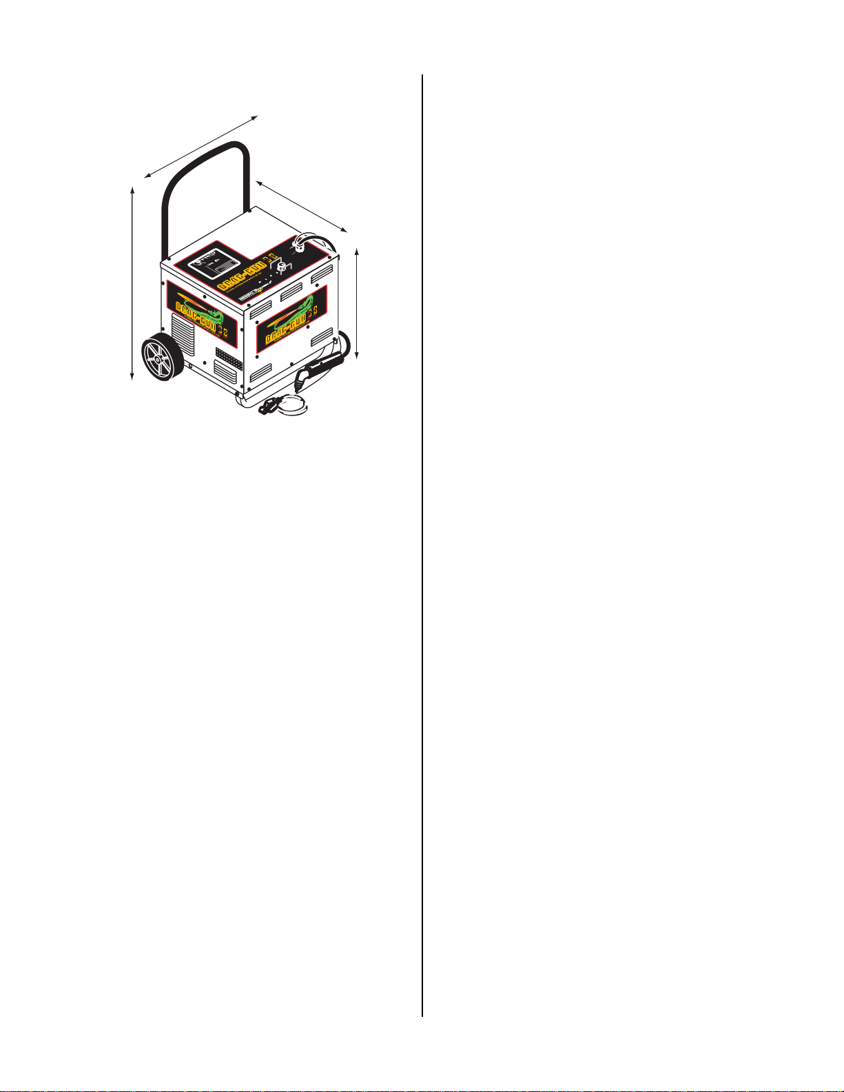
12. Dimensions
A-02146
15.5 inches (393.7 mm)
22 inches (558.8 mm) (incl. wheels)
17 inches
(39.37mm)
38.5 inches
(977.9 mm)
23x4334REVA
MADEINTHEUSA
TM
23x4334REVA
MADEINTHEUSA
TM
CURRENT
12 29
20
ACGASDC
OVER
TEMP
WORK
TORCH
®
R
MADE INTHE USA
TM
0.1in(2.5mm)Examinefor
elongated,cratered,or
oversizedorifice.
Electrode9-6506
GasDistributor 9-6507
Tip 9-6501
ShieldCup9-6003
PartDescription Catalog No.
REPLACEMENT
TORCHPARTS
Checkthe electrode and tip for excessive wear.
Replaceelectrode if worn back morethan 0.1"
(2.5mm). Check tip orifice for out-of-round wear.
TorchHeadAssembly
ShieldCup
Gas
DistributorTip
Electrode
ProperAssemblyof TorchHeadComponents

Manual 0-2879 3-1 INSTALLATION PROCEDURES
SECTION 3:
INSTALLATION
PROCEDURES
3.01 Introduction
This section describes installation of the Plasma Cutting
System. These instructions apply to the Power Supply,
TorchandLeadsAssemblies only; installation procedures
for any Options or Accessories are given in manuals spe-
cifically provided for those components.
3.02 Site Location
Select a clean, dry location with good ventilation and ad-
equate working space around all components.
CAUTIONS
Operation without proper air flow will inhibit
proper cooling and reduce duty cycle.
To prevent entry of cutting or other metal debris,
the power supply must not be operated in the hori-
zontal position. Operate the power supply in the
vertical position only with the handle in the up-
right position.
The power supply is cooled by air flow through the end
and side panels. Air flow must not be obstructed. Pro-
vide at least 12 inches (300 mm) clearance on each side.
Provide sufficient clearance above unit to allow access to
top panel controls (minimum 12 inches or 300 mm).
NOTE
Review the safety precautions in Section 1 of this
manual to be sure that the location meets all safety
requirements.
3.03 Unpacking
A. Shipping Box
The product is packaged and protected to prevent dam-
age during shipping.
1. Unpack each item and remove all packing mate-
rial.
2. Locate the packing list(s) and use the list to iden-
tify and account for each item.
3. Inspect each item for possible shipping damage.
If damage is evident, contact your distributor or
shipping company before proceeding with sys-
tem installation.
B. Removing Skid
The base of the power supply is secured to the skid with
lag screws. Remove the power supply from the skid per
the following procedure:
1. Remove the four lag screws securing the Power
Supply to the skid. There are two lag screws on
each side.
2. Lift unit from the skid and set the unit aside.
3.04 Handle Installation
The Handle must be attached to the Power Supply.
1. Locate the Handle and four hex head bolts (1/4-
20 x 1-1/4 inch) in the shipping package.
2. Align the holes in the Handle with the four holes
in the Rear Panel.
3. Secure the Handle to the Rear Panel with the sup-
plied hex head bolts.
4. Tightenthe bolts being careful not to over tighten.
3.05 Electrical Connection
CAUTION
The primary power source, power cable, and plug
all must conform to local electrical codes, recom-
mendedcircuitprotectionand wiring requirements.
• Domestic Units
The Power Supply operates on 208/230 VAC
(±10%), single-phase, 60 Hz input power. The
208VAC unit draws 26 amperes and the 230VAC
unit draws 23 amperes of input current. The in-
put power electrical service for the Power Supply
must be fused for at least 30 amperes. The electri-
cal outlet should be within 10 ft (3.0 m) of the
Power Supply.
• CE and Australian Units
The Power Supply operates on 220 VAC (±10%),
single-phase, 50/60 Hz input power. The input
powerelectricalservice for the Power Supplymust
be fused for at least 25 amperes. The electrical
outlet should be within 9 ft (2.9 m) of the Power
Supply.
INSTALLATION PROCEDURES 3-2 Manual 0-2879
3.06 Torch Connection
The Torch is installed to the Power Supply when ordered
as part of the system. Use the following procedure only
if the Power Supply and Torch were ordered separately:
1. Remove the Right Side Panel of the Power Sup-
ply per Section 5.08-A-1.
2. Locate the Torch Block area as shown in the fol-
lowing Figure.
A-03238
Torch Block
Area
Figure 3-1 Torch Block Area Location
NOTE
Note that all wires are outside the protective insu-
lating sheet.
3. Remove the strain relief nut from the strain relief
on the Torch Leads Assembly.
4. Feed the ends of the Torch Leads Assembly
through the hole in the Power Supply Panel.
5. Place the strain relief nut back over the end of the
Torch Leads and secure the strain relief to the
panel with the nut.
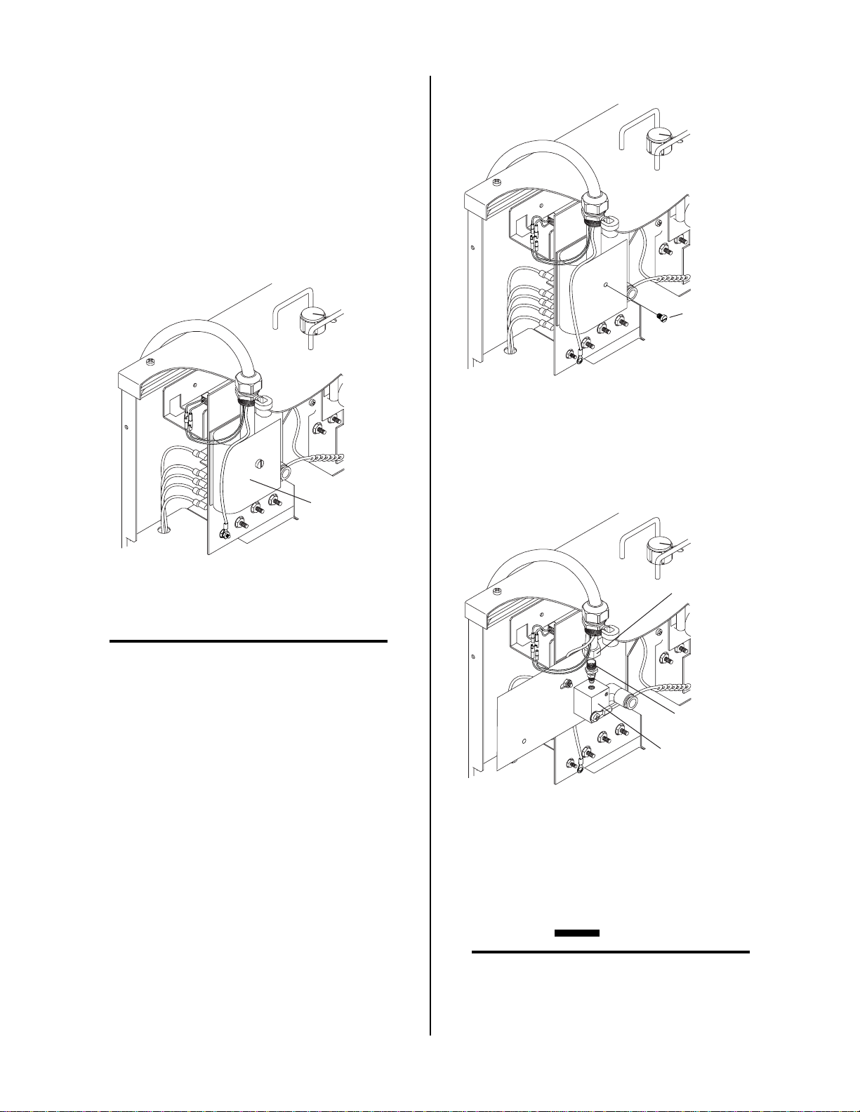
6. Remove the nylon screw holding the protective
insulating sheet to the bulkhead.
A-03247
Nylon Screw
Removal
Figure 3-2 Nylon Screw
7. Connect the Torch Negative Lead to the fitting in
the brass torch bulkhead.
A-03240
Torch Lead
Fitting
Torch Negative
Lead
Bulkhead
Figure 3-3 Negative Torch Lead Connection
8. Close the protectiveinsulating sheet back over the
torch bulkhead and secure with the nylon screw
removed earlier (see CAUTION).
CAUTION
Be sure all wires are outside the protective insulat-
ingsheetwhenthenylonscrew is reinstalled. High
voltage is present on the torch negative lead.

Manual 0-2879 3-3 INSTALLATION PROCEDURES
9. Connect the two torch control connectors and the
pilot wire to the Main PC Board Assembly con-
nections.
A-03239
Torch Control
Connectors
Pilot Wire
Connection
Figure 3-4 Wiring Connections
10. Close the Power Supply by reinstalling the Right
Side panel.

INSTALLATION PROCEDURES 3-4 Manual 0-2879
Other manuals for 38 Cutmaster
3
Table of contents
Other Thermal Dynamics Power Supply manuals

Thermal Dynamics
Thermal Dynamics CE CutMaster 50 User manual

Thermal Dynamics
Thermal Dynamics MERLIN 6000 User manual

Thermal Dynamics
Thermal Dynamics PakMaster XLPLUS 50 User manual

Thermal Dynamics
Thermal Dynamics CE PAKMaster 75 XL Plus User manual

Thermal Dynamics
Thermal Dynamics CE PAK Master 75XL User manual

Thermal Dynamics
Thermal Dynamics Pak Master 100XL User manual

Thermal Dynamics
Thermal Dynamics Pak Master 75XL Plus User manual

Thermal Dynamics
Thermal Dynamics MERLIN 3000 User manual

Thermal Dynamics
Thermal Dynamics CE CutMaster 50 User manual

Thermal Dynamics
Thermal Dynamics Pak Master 75XL Plus User manual


