Inaxsys SW1210-16CB Technical manual

SW1210-16CB
1. Overview:
The Inaxsys SW1210-16CB switching power supply/distribution unit converts 120VAC input into 12VDC
at 11 amps of continuous supply current. The built-in 16-output distribution board allows for power
delivery across multiple outputs while offering electronically fused protection on each circuit. This general-
purpose power supply has a wide range of applications for access control, security and CCTV systems
that require additional power. For convenient installation, the unit comes completely assembled with a
compact steel enclosure, power cord and all connecting hardware.
2. Features:
● Designed for quick installation
● Individually protected, electronically fused outputs
Built in battery backup/charger on selected models(see below)
● Short circuit isolation technology for uninterrupted operation
Class 2, Power limited outputs
● Removable output terminal blocks for quick installation
● Diagnostic LEDs for quick troubleshooting
Automatic switch over to stand-by battery
● AC line cord included
● Lifetime warranty
3. Specifications:
UL listed to UL-60950 Information Technology Equipment.
CE/LVD EN60950-1
CE/EMC:EN55022,EN55024
FCC PART 15, ICES 003-2012
● Maximum temperature range:-20° C to 40° C; (For indoor use only.)
● Relative humidity: 20% ~90%
85% of Efficiency with full load.
Maximum ripple 150mVp-p, Maximum noise 200mVp-p
Built-in charger for sealed lead acid battery.
Individual outputs current limited at 2.5 Amps per circuit.
Maximum battery charge 500mA (Subtract from total output).
Red LED’s indicate DC power presence on each circuit.
Products
Power output
Number of
outputs
Battery
Charger
Enclosure dimensions
SW1205-4CB
12VDC@5.5 Amps
4
Yes
9.25”. x 8.25” in. x 3.5”
(23.3 cm x 21 cm x 9 cm)
SW1205-8CB
12VDC@5.5 Amps
8
Yes
9.25”. x 8.25” in. x 3.5”
(23.3 cm x 21 cm x 9 cm)
SW1210-8CB
12VDC@11 Amps
8
Yes
17”L x 13.5”W x 4.75”H
(43.2 cm x 34.3cm x 12.06 cm)
SW1210-16CB
12VDC@11 Amps
16
Yes
17”L x 13.5”W x 4.75”H
(43.2 cm x 34.3cm x 12.06 cm)
Note: When using the battery charger for backup /charging, 500mA needs to be subtracted from the total
output power listed above in table.
Products
AC current draw
(Full load)
120VAC@50/60hz
AC current draw
(Full load)
240VAC 50/60Hz
Max output
per circuit
Number of
batteries required
for backup
SW1205-4CB
1.3Amps
650mA
2.5Amps
1
SW1205-8CB
1.3Amps
650mA
2.5Amps
1
SW1210-8CB
2.6Amps
1.3Amps
2.5Amps
2
SW1210-16CB
2.6Amps
1.3Amps
2.5Amps
2
Equipment is to be installed and serviced by authorized / trained
personnel only. Installation should conform to all local codes and in accordance
with the National Electrical Code. Shut branch circuit power before installing /
servicing equipment. Product is intended for indoor use only.
4. Installation Instructions:
1. Unpack product. Do not discard packaging material until installation is complete.
2. Pre-drill holes on the wall where enclosure is to be mounted. Choose a vertical surface (wall)
strong enough to support the full weight of the assembly. Select a mounting location in an area
without excessive moisture; for indoor installation only and in a secured area (Electrical Room).
3. Secure enclosure to the desired wall location with the
appropriate sized fasteners using the four mounting
holes in the cabinet.
4. Disconnect power to the branch circuit to which the
product will be connected.
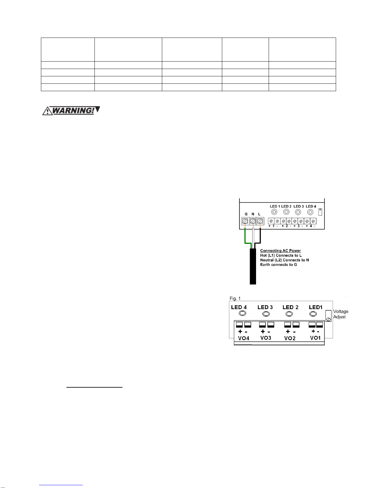
5. Connect incoming AC power (120 V, 60 Hz):
–Hot (L1) (black) to terminal marked “L”.
–Neutral (L2) (white) to terminal marked “N”.
–Ground (Green) to terminal marked “G”.
6. Use the knockout in bottom of cabinet for 120 VAC
wiring. Route the 120VAC wiring at least 1/4" from (low
voltage) wiring.
7. Keep a 1/4" (0.635 cm) separation between power-
limited wiring and on-power-limited wiring. Use separate
knockouts for power limited wiring.
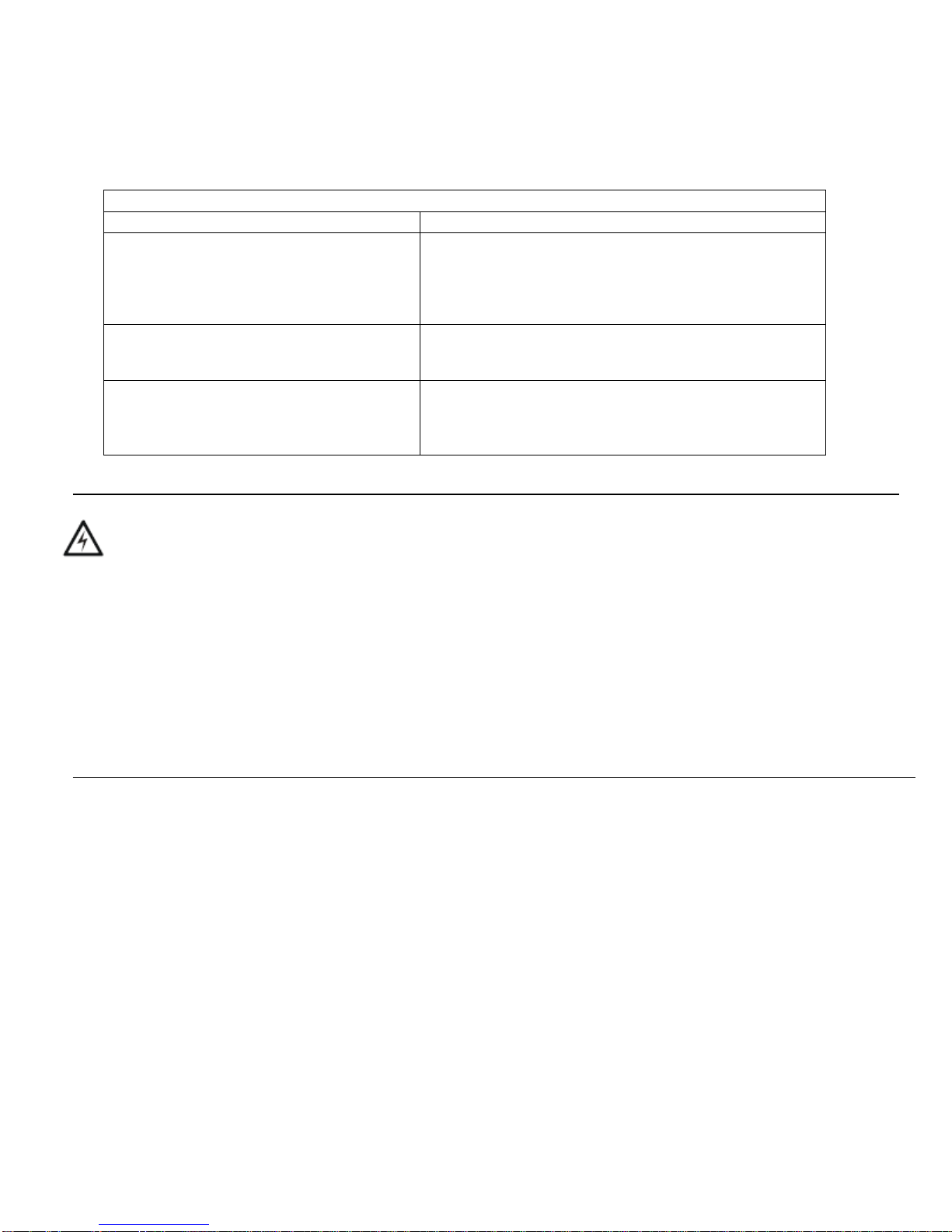
8. Connect external loads to appropriate terminals shown in
Fig 1: Connect circuit #1 to terminals marked “VO1+” and
“VO1–”. Connect circuit #2 to terminals marked “VO2+”
and “VO2–”. Continue to connect the remaining circuits,
carefully observing polarity.
9. Power the branch circuit and observe red output LEDs
illuminated. Illuminated LEDs 1-4 or 1-8 mean that Dc
power is present on outputs.
10. To avoid potential damage, verify that output voltage and load current does not exceed output
limitations. (A single extinguished LED can mean an overload condition) See troubleshooting
guide for more information.
11. For Battery backup: If battery backup is required, use the provided battery leads and connect
the Lead Acid battery(s) 7AH 12V to the battery charger terminals while carefully observing
polarity. Set the output voltage on the trim pot shown in Fig. 1 to 13.8VDC for proper charging.
Battery(s) not supplied with power supply unit. We suggest using Power Sonic Battery part NO.
PS1270, UL File NO.MH20845 or any Recognized Lead Acid UL Battery of same capacity and
type,7AH 12V.
5. Maintenance/Troubleshooting
Product should be tested annually for proper functionality. Normal verification of proper operation
includes measuring all outputs with a voltmeter under normal load conditions to ensure output voltage
is present.
Trouble shooting tips:
Symptom
Check for
All output LEDs are extinguished
Measure for proper input voltage
(120VAC/240VAC) using an AC voltmeter.
Verify total output load. Check for
overload/Short circuit condition on all outputs.
Remove short or overload condition.
Single output LED is extinguished
Verify output load on circuit. Check for
overload/Short circuit condition. Remove short
or overload condition.
Battery not charging.
Measure battery charger voltage to ensure
13.8VDC is present.
Check battery to make sure it is not worn out or
defective.
WARNING: TO REDUCE THE RISK OF FIRE OR ELECTRIC SHOCK, DO NOT
EXPOSE THIS APPLIANCE TO RAIN OR MOISTURE. RISK OF ELECTRICAL
SHOCK AND/OR EQUIPMENT DAMAGE. DISCONNECT POWER BEORE
SERVICING THIS APPLIANCE.
• FOR CONTINUOUS PROTECTION AGAINST HAZARD, REPLACE FUSES WITH ONLY EXACT TYPE
AND RATING.
• MAINTAIN A 1/4" OF SEPARATION BETWEEN THE AC MAINS AND ALL LOW VOLTAGE WIRING.
• A READILY ACCESSIBLE SWITCHED CIRCUIT BREAKER MUST BE AVAILABLE TO DISCONNECT
MAIN POWER AS REQUIRED.
• THIS UNIT CONTAINS NO USER-SERVICEABLE PARTS, INSTALLATION AND SERVICING
SHOULD ONLY BE MADE BY QUALIFIED PERSONELL.
• INSTALL IN ACCORDANCE WITH LL LOCAL REGULATIONS AND NATIONAL ELECTRIC CODE.

G N L
8272 Rue Pascal-Gagnon
Saint Leonard, Quebec
H1P 1Y4
Website: www.inaxsys.com
Toll Free: 888-648-6648
Support: support@inaxsys.com
Sales: [email protected]
SW1210-16CB
AC power input
Power Module 1: Output
Terminal Block for circuits 1-4
and Voltage Adjustment
Power Module 1: Output Terminal
Block for circuits 5-8 and Voltage
Adjustment
Power Module 2: Output
Terminal Block for circuits 1-4
and Voltage Adjustment
Power Module 2: Output
Terminal Block for circuits 5-8
and Voltage Adjustment
This manual suits for next models
3
Other Inaxsys Power Supply manuals


