Installing the Required Components
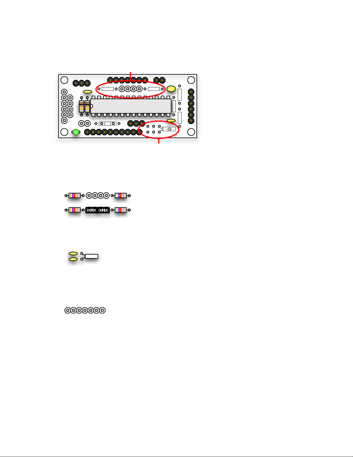
The following components are required for all configurations.
1 - 28-pin socket for uM-FPU64
1 - 10uF Tantalum capacitor (low ESR)
2 - 0.1 uF capacitors
2 - 10K resistors
1 - LED (note: + anode (long lead) is on the left)
various 0.1” headers
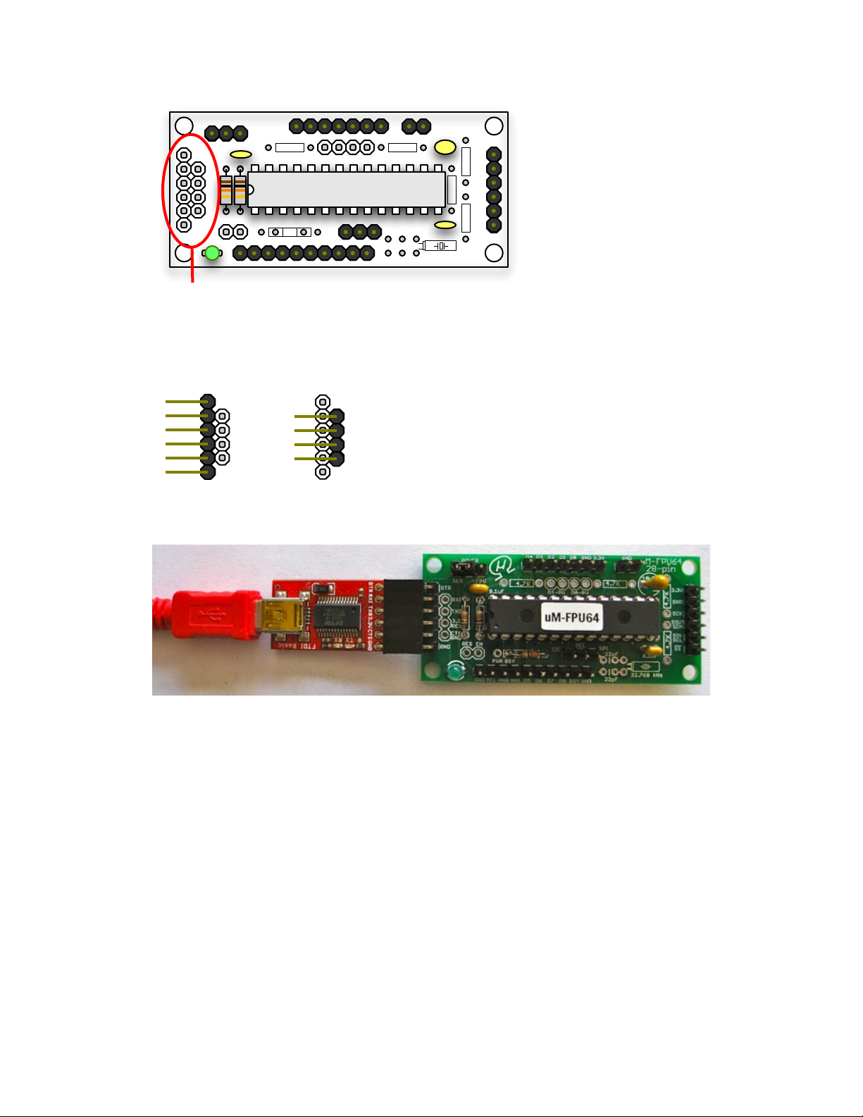
Male or female headers can be installed for each of the breakout connectors and jumpers. The following photo
shows the breakout board after the required components and headers have been installed, and a right-angle
header has been installed for the serial connector. See the Serial Connection section for additional information
regarding the serial connector.
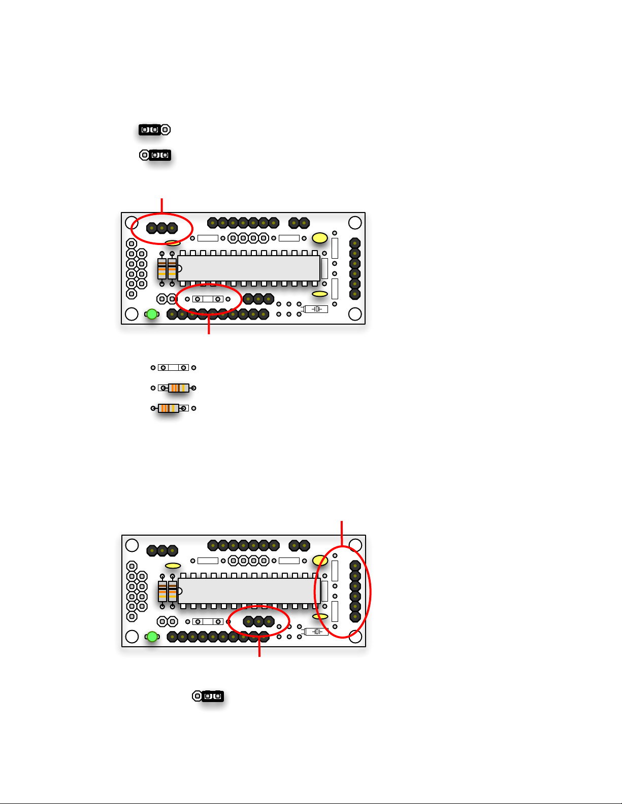
Power Selector and LED Resistor
The breakout board can be configured to draw power from the serial connector 3.3V pin, or the interface
connector 3.3V pin. The interface connector should be used for power when connecting the uM-FPU64 to
other components, since the serial connector can only supply a limited amount of current. Using the serial
connector to supply power is convenient for development, since no external power supply is required, but care
should be taken to ensure that the current requirements of your circuit are within the limits that can be provided
by the serial connection.
The LED can be configured as a power on indicator, or as a busy indicator, depending on the placement of the