Mid-Continent Instrument TRUE BLUE POWER TB40 Series Technical Document

Revision F • June 23, 2022

1 Manual Number 9019288 • Revision F, June 23, 2022
FOREWORD
This manual provides information intended for use by persons who, in accordance with current
regulatory requirements, are qualified to install this equipment. If further information is required,
please contact:
True Blue Power
c/o Mid-Continent Instrument Co., Inc.
Attn: Customer Service Dept.
9400 E. 34th St. N.
Wichita, KS 67226 USA
Phone 316-630-0101
Fax 316-630-0723
www.truebluepowerusa.com
www.mcico.com
We welcome your comments concerning this manual. Although every effort has been made to
keep it free of errors, some may occur. When reporting a specific problem, please describe it
briefly and include the manual part number, the paragraph/figure/table number and the page
number. Send your comments to:
True Blue Power
c/o Mid-Continent Instrument Co., Inc.
Attn: Technical Publications
9400 E. 34
th
St. N.
Wichita, KS 67226 USA
Phone 316-630-0101
Fax 316-630-0723
© Copyright 2019
Mid-Continent Instrument Co., Inc.
Download the current
version of this
installation manual
using your
smartphone or tablet.

2 Manual Number 9019288 • Revision F, June 23, 2022
TABLE OF CONTENTS
SECTION 1GENERAL DESCRIPTION 4
1.1INTRODUCTION 4
1.2PHYSICAL ATTRIBUTES 4
1.3UNIT ARCHITECTURE 5
1.4TECHNICAL SPECIFICATIONS 6
1.5IMPORTANT SAFETY INFORMATION 8
SECTION 2PRE-INSTALLATION CONSIDERATIONS 10
2.1COOLING 10
2.2EQUIPMENT LOCATION 10
2.3ROUTING OF CABLES 10
2.4LIMITATIONS 11
2.5MODIFICATION 11
SECTION 3INSTALLATION 12
3.1GENERAL 12
3.2PRE-INSTALLATION INSPECTION 12
3.3PARTS 12
3.4INSTALLATION 13
SECTION 4OPERATION 21
4.1DESCRIPTION 21
4.2CONSTRUCTION AND THERORY OF OPERATION 21
4.3OPERATIONAL MODES 24
4.4BATTERY COMMUNICATION 29
4.5PERFORMANCE 35
SECTION 5CONFORMANCE 37
5.1DISPATCH VERIFICATION AND IN-FLIGHT MONITORING 37
5.2INSTRUCTIONS FOR CONTINUED AIRWORTHINESS 37
5.3CONTROL MODE 38
5.4OPTIONAL SERVICE 41
5.5COMPONENT SERVICE 43
5.6STORAGE INFORMATION 44
5.7END OF LIFE 45
5.8DISPOSAL 45
5.9DO-311A COMPLIANCE QUALIFICATION FORM 46
5.10DO-160 ENVIRONMENTAL QUALIFICATION FORM 47

3 Manual Number 9019288 • Revision F, June 23, 2022
REVISION HISTORY
Rev Date Detail Approved
A
08/02/2019 Initial release. BAW
B 10/01/2019 Revised EQF, added DO-311A Compliance Qualification
Form and provided additional limitation details (sec 2.5) WVC
C 05/21/2020
Updated style and brand to meet Marketing and
Engineering guidelines.
Added downloadable event log feature and instructions to
load/download custom configuration parameters. Updated
DO-160 qual and installation instructions to include
grounding recommendations.
DLR
D 12/30/2020 Revised mounting instructions, corrected number of cells,
updates related to software version 1.0.2. WVC
E 01/06/2022 Added recommended chargers; updates related to
software version 1.0.3; updated EQF. WVC
F 06/23/2022 Updated ARINC 352 status; revised EQF. VAA

4 Manual Number 9019288 • Revision F, June 23, 2022
SECTION 1 GENERAL DESCRIPTION
1.1 INTRODUCTION
The TB40 series Advanced Lithium-ion Battery, part numbers 6430040-( ), are designed to deliver
high current capability to start piston and turbine aircraft engines and subsequently, provide power
to the aircraft electrical bus in the event of generator function loss. The TB40 is a sophisticated
energy storage and power system that utilizes state-of-the-art Nanophosphate® lithium-ion battery
cell technology to optimize performance, safety, life and weight when compared to traditional or
competing aircraft batteries. The design of the battery includes detailed focus on key electrical,
mechanical, and software elements that combine to provide exceptional performance and safety
that meets and exceeds the latest regulatory and industry standards. The TB40 is a complete
battery solution providing significant value and benefit to an aircraft designer, owner and operator.
Key features of the TBX series (inclusive of the TB20, TB30, TB40 and TB60) include real-time
state of charge and capacity reporting, programmable battery parameters configurable to individual
installations, and maintenance-free operation with on-condition end of life. Multiple safety
protections, continuous data monitoring, and an on-board status indicator also add value,
reliability, and reduced cost of ownership for the life of the product.
The TBX series Advanced Lithium-ion Batteries require professional use and minimal service to
deliver maximum performance and value as designed. This manual contains information related to
the specifications, installation, operation, storage, scheduled service and other related topics
associated with the proper care and use of this product.
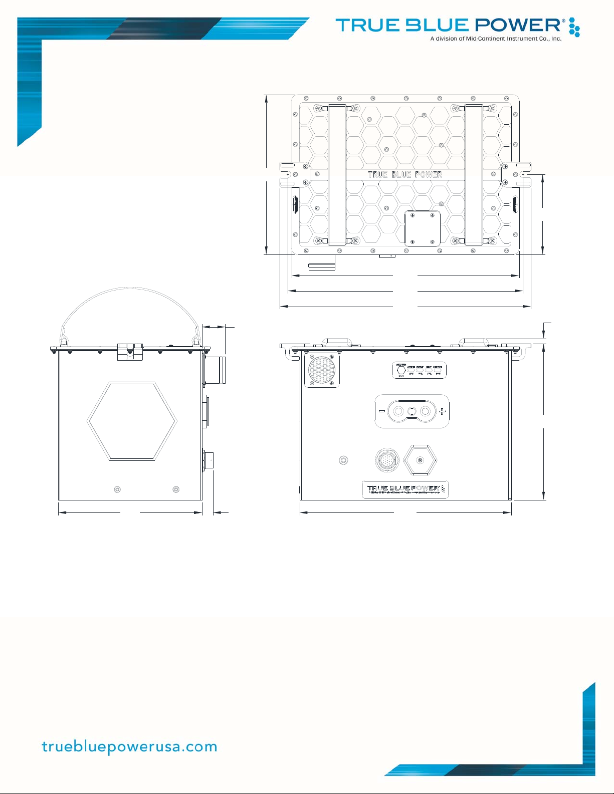
1.2 PHYSICAL ATTRIBUTES
The TB40 is a single, integrated component contained in a metal enclosure with multiple interface
connections. There is a primary 2-pin, industry standard mil-spec quick disconnect power
receptacle, an 18-pin circular communications connector, and a threaded grounding location. A
USB service port and an integrated push-button status indicator with LED indicators are available
for ground operations as well. The lid of the enclosure includes two hold-down features on either
side to support typical aircraft mounting. Handles integrated into the lid of the enclosure provide
ease of lifting and carrying for installation, removal and transport. The 1.50 inch diameter vent port
can be located on either the front or top of the unit for an exhaust connection that directs any
released emissions appropriately.

5 Manual Number 9019288 • Revision F, June 23, 2022
1.3 UNIT ARCHITECTURE
The unit is comprised of two primary building blocks:
Battery cell modules with on-board monitoring, logic, and protections
Battery Management System (BMS) with control and communication functions
Each battery module consists of thirty-two (32) cells arranged as eight (8) groups of four (4)
parallel cells, connected in series. The cells are connected with welded bus bars which contain an
individual fuse for each cell in the module. Each module contains multiple temperature monitors
and an integrated heater that improves cold weather performance. Four modules connected in
parallel through a network of bus bars provide combined power to the main connector and thus the
aircraft.
The Battery Management System (BMS) is a microprocessor-based system that monitors
individual signals provided by each module, manages battery operation and reports status
information to the aircraft. It also manages heater functionality, stores operating parameters,
contains an event log and provides interface capability.
Additional components in the unit include independent Resistance Temperature Detectors (RTDs)
that produce analog electrical signals accessible through the 18-pin connector for redundant
temperature monitoring.

6 Manual Number 9019288 • Revision F, June 23, 2022
1.4 TECHNICAL SPECIFICATIONS
Electrical Attributes
Power Input 28.8 volts DC Nominal, 400A Max
Power Output 26.4 volts DC Nominal, Continuous Current 525A;
Power Peak Current (IPP) 1390A (at 18.5V CV discharge);
Power Rated Current (IPR) 1125A (at 18.5V CV discharge)
Battery Capacity
(Beginning of Life)
40 amp hours (Ah) @ 23°C
Table 1.1
Physical Attributes
Weight 36.6 pounds (16.65 kg)
Dimensions at base
(not including vent, lid and
connectors)
12.1 x 8.21 x 9.2 inches (see Figure 1.1)
[308 x 208 x 236 mm]
Quick Disconnect Power Receptacle
Communications Connector
USB Service Data Port
2-pin per MIL-PRF-18148/3 form factor (MS3509)
18-pin per MS3114E14-18P
USB 2.0, Type-A port
Mounting See Section 3.4.2
Table 1.2
Qualifications
Certification FAA TSO-C179b, Class A-4B
Performance Qualification RTCA/DO-311A Minimum Operational Performance
Standard for Rechargeable Lithium Batteries and Battery
Systems (See Section 5.9)
Environmental Qualification RTCA/DO-160G (See Section 5.10)
Software Qualification RTCA/DO-178C, Design Assurance Level (DAL) A
Table 1.3

7 Manual Number 9019288 • Revision F, June 23, 2022
12.1
8.9
0.3
13.0
13.5
9.1
4.6
14.4
1.3
8.2 0.6
Figure 1.1
Outline Drawing

8 Manual Number 9019288 • Revision F, June 23, 2022
1.5 IMPORTANT SAFETY INFORMATION
Read this safety information BEFORE maintaining or servicing the battery.
1.5.1 Symbol Definition
This section describes the precautions necessary for safe operations. The following safety
symbols have been placed throughout the guide.
Warnings identify conditions or practices that could result in personal injury.
Cautions identify conditions or practices that could result in damage to the equipment.
1.5.2 Handling Precautions
The battery pack’s energy is high enough to sustain an ARC flash. Always wear safety
glasses, fire retardant smocks, and use insulated tools when servicing the battery.
Remove metal items such as rings, bracelets, and watches when working with battery
packs. A battery could produce a short circuit current high enough to weld jewelry to metal
and cause a severe burn.
Always use appropriate Electrostatic Discharge (ESD) protection while working with the
battery pack.
All connections for battery pack testing must include appropriate short-circuit protection.
The battery pack service area shall be properly ventilated and egress paths shall be
unobstructed.
Specialized breathing filters are not required under normal use.
Always use electrically insulated tools.
Never smoke or allow a spark or flame near the battery pack.
Use caution to reduce the risk of dropping a metal tool on the battery. Dropping a tool
could spark or short circuit the battery pack.
Turn all accessories off before removing the ground terminal.
Use appropriate lifting devices or equipment for handling batteries; use battery handles
where provided.
W
ARNING
CAUTION
W
ARNING

9 Manual Number 9019288 • Revision F, June 23, 2022
1.5.3 Additional Precautions
The following design and operation factors are required for safe use.
It is not acceptable to combine or use any battery cells or modules other than those
approved by True Blue Power within this battery pack.
There are no limitations in storing or using this battery in the vicinity of other battery
chemistries. This battery does not emit or absorb any gas during storage, transportation or
during normal operating conditions.
Batteries must not be installed with the output terminals reversed. A reversed battery could
be charged by other batteries in the circuit during discharge; or discharged by the charging
system during charge.
Battery terminals must be covered with non-conductive protective devices to avoid any
possibility of shorting during handling, shipping or storage.
1.5.4 Shipping
True Blue Power lithium-ion cells and batteries are designed to comply with all applicable
shipping regulations as prescribed by industry and regulatory standards. This includes
compliance with the UN recommendations on the Transport of Dangerous Goods, IATA
Dangerous Goods Regulations, applicable U.S. DOT regulations for the safe transport of
lithium-ion batteries, and the International Maritime Dangerous Goods Code. In accordance
with IATA and per UN 3480, PI 965, Section 1A and 1B, when shipped by air, the True Blue
Power Advanced Lithium-ion Battery will be shipped with a state of charge (SOC) not to
exceed 30% of rated capacity. This battery is classified as a Class 9 Dangerous Goods. If the
battery requires shipment, please refer to Section 5.4.5 or contact the manufacturer for
additional instructions on proper procedures.
NOTE: The unit is shipped with approximately 30% state-of-charge (SOC). Upon
receipt the battery shall be fully charged using the procedures listed in this manual
(prior to storage and again prior to installation/use).
Upon receipt the battery shall be fully charged. Batteries that are stored thereafter shall be
fully recharged at a minimum every six (6) months, following the procedure set forth in
Section 5.4.2. For more detailed storage instructions refer to Section 5.6.
CAUTION
CAUTION

10 Manual Number 9019288 • Revision F, June 23, 2022
SECTION 2 PRE-INSTALLATION CONSIDERATIONS
2.1 COOLING
No internal or external cooling of the unit is required. The unit is designed to operate over a wide
temperature range and includes internal thermal monitoring and protection circuits. See Section 4
for more details.
2.2 EQUIPMENT LOCATION
The True Blue Power Advanced Lithium-ion Battery is designed for mounting flexibility, allowing for
installation with no requirement for temperature or pressure control. Although not required,
optimum performance and life can be achieved by mounting the battery in a temperature controlled
section of the aircraft. In addition to altitude and temperature tolerance, the unit is designed to
withstand high levels of condensing humidity. However, installation locations where the unit could
be subject to standing or direct water exposure should be avoided. The unit should be mounted in
the upright position.
Failure mode, effects, and criticality analysis of the battery has shown that the potential for the
release of toxic or flammable gases as a result of any potential condition is extremely
improbable. However, for additional risk mitigation, the unit is designed with a vent which should
be connected and diverted overboard in the event of such an occurrence. Details for vent
installation are provided in Section 3. For additional precaution, installation near potential sources
of ignition should be avoided.
Consideration should be given to how the status and reporting functions of the battery will be
displayed within the aircraft. At a minimum, critical parameters determined at the time of
certification should be available to the pilot and/or crew. Additionally, existing aircraft systems
which are designed to work with traditional batteries may need alteration in order to accommodate
the slight change in voltage output of this lithium-ion battery and the communication capabilities
available.
2.3 ROUTING OF CABLES
The power terminal wires associated with the unit are heavy gauge wire and carry significant
power. Be aware of routing cables near other electronics or with other wire bundles that may be
susceptible to high energy flow.
Avoid sharp bends in both the power cables and the signal cabling and be cautious of routing near
aircraft control cables. Also avoid proximity and contact with aircraft structures, avionics
equipment, or other obstructions that could chafe wires during flight and cause undesirable effects.
Cables should not run adjacent to heaters, engine exhausts, or other heat sources. The signal
cable bundle wires are recommended to be no smaller than 24 gauge.

11 Manual Number 9019288 • Revision F, June 23, 2022
2.4 LIMITATIONS
The conditions and tests for TSO approval of this article are minimum performance standards.
Those installing this article, on or in a specific type or class of aircraft, must determine that the
aircraft installation conditions are within the TSO standards. TSO articles must receive additional
installation approval prior to being operated on each aircraft. The article may be installed only
according to 14 CFR Part 43 or the applicable airworthiness requirements.
The TBX series operates at temperatures up to 70°C. If, however, internal cell temperatures
exceed 72°C, charging is disabled until cell temperatures fall below 62°C.
2.5 MODIFICATION
This product has a nameplate that identifies the manufacturer, part number, description,
certification(s) and technical specifications of the unit. It also includes the “MOD” or modification
number representing notable changes in the hardware design of the unit.
Modification (MOD) 0 is the initial release of the product and is identified on the nameplate by the
lack of marking on the MOD numbers 1 through 9 (i.e. 1-9 are visible). All subsequent
modifications are identified on the nameplate by the marking/blacking out of that particular MOD
number (i.e. for MOD 1, the number 1 is not visible and 2-9 are visible - see Figure 2.1 for
examples). MODs do not have to be sequentially inclusive and may be applied independent of
each other.
For additional details regarding specific changes associated with each MOD status refer to the
product published Service Bulletins at www.truebluepowerusa.com.
Figure 2.1
Nameplate and MOD Status Example
MOD 0
MOD 1
MOD 1
& MOD 2

12 Manual Number 9019288 • Revision F, June 23, 2022
SECTION 3 INSTALLATION
3.1 GENERAL
This section contains mounting, electrical connections and other information required for
installation. These instructions represent a typical installation and are not specific to any aircraft.
3.2 PRE-INSTALLATION INSPECTION
Unpacking: Carefully remove the battery from the shipping container. The shipping container and
packing are designed specifically for the transit of lithium batteries and approved by international
transportation agencies. These materials should be retained for use should the unit require future
shipment.
Inspect for Damage: Inspect the shipping container and unit for any signs of damage sustained in
transit. If necessary, return the unit to the factory using the original shipping container and packing
materials. File any claim for damages with the carrier.
Note: The unit is shipped at approximately 30% state of charge (SOC).
Upon receipt, the battery shall be fully charged using the procedures listed
in this manual (prior to storage and again prior to installation/use).
3.3 PARTS
3.3.1 Included Parts
A. TB40 Advanced Lithium-ion Battery MCIA P/N 6430040-( )
B. Installation and operation manual MCIA P/N 9019288
3.3.2 Available Parts
A. Connector Kit MCIA P/N 9018042-1
i. Power Connector Kit
ii. Communications connector kit
B. Vent Kit MCIA P/N 9018043
i. High temp vent hose (48”)
ii. Vent clamps (x2)
C. Helicopter Mounting Kit MCIA P/N 9019576-3
i. Corner Brackets (x4)
ii. Silicone Pad
D. MX Charger MCIA P/N 282-101
E. PRO Charger MCIA P/N ACM-1260-101
3.3.3 Installer Supplied Parts
A. Wires
B. Appropriate hold-down hardware
CAUTION

13 Manual Number 9019288 • Revision F, June 23, 2022
3.4 INSTALLATION
DO NOT SHORT TERMINALS AT ANY TIME!
Extreme care and caution should be applied when handling and connecting to the unit. Danger of
short circuit and subsequent arc flash, electrical burns or equipment damage can occur if not
handled properly.
Install the battery in the aircraft in accordance with the aircraft manufacturer’s instructions and the
following sections. If connecting batteries in parallel contact manufacturer for guidelines on parallel
operation.
3.4.1 Harness Preparation
Prepare aircraft wiring with mating connectors in accordance with the proper Wire Size and
Type (Table 3.1), Connection Features (Figure 3.1) and Pin Identification Diagrams (Figures
3.3 and 3.4).
Proper grounding requires connecting the ground lug on the chassis to the aircraft frame. In
addition, connect the ground lug to the 18-pin data communication connector backshell along
with the cable shield and any signal shields.
Use of PTFE, ETFE, TFE, Teflon or Tefzel insulated wire is recommended for aircraft use.
Recommended wire sizes and types are identified in Table 3.1 below. *Note: Wire gauge size
for power connections is dependent on the particular aircraft installation, taking into
consideration cable length, load profile, etc.
Table 3.1
Wire Size and Type
Wire Size and Type
Wire Gauge Wire Type Connector Pins
000 AWG * Stranded Copper Power +/-
18-24 AWG Stranded Copper Comm (18-pin) A-U
W
ARNING

14 Manual Number 9019288 • Revision F, June 23, 2022
Figure 3.1
Connection Features
5.1
5.7
3X
2.3
2.5
5.0
7.4
1.3
Figure 3.2
Connection Locations
¼-20 Threaded Ground Lug
Quick Disconnect Receptacle
per MS3509 (MIL-PRF-18148/3)
18-
p
in Data Communication
USB Access Cover
1½ inch Vent Port

15 Manual Number 9019288 • Revision F, June 23, 2022
LA
KMNB
C
PUTJ
HSRD
EFG
Figure 3.3
Communication Connector
Table 3.2
Communication Connector Pinout
Figure 3.4
Power Connector
* Note: Communication Connector pin P is a BMS ground reference.
This does not apply to any of the TBX battery models with p/n ending in -1.
Communication Connector
(18-pin)
Pin
Description
A Analog SOC
B Battery Disable Input
C Heater Disable Input
D RTD-1A
E RTD-1B
F RTD-2A
G RTD-2B
H ARINC 429 (A)
J Service Discrete
K Fault Discrete
L Heating Discrete
M Min Capacity Discrete
N Analog Ground
P Spare / BMS Ref *
R Spare
S ARINC Shield
T Engine Start Discrete
U ARINC 429 (B)
Power Receptacle
(2-pin)
Pin
Description
+
28VDC power in
-
Aircraft Ground
Positive/
Power Pin
Negative/
Ground Pin

16 Manual Number 9019288 • Revision F, June 23, 2022
3.4.2 Securing the Unit
The battery is designed to be secured in the aircraft using hold-down rods. The hold-down
features are integrated into the lid of the battery. The hold-down consists of a slot for the
hold-down rod, open to the outboard sides, and two perpendicular slots on each side to keep
the rod vertical using an alignment washer. The battery is then secured with the appropriate
nut or hardware designed to mate with the rod. Tighten the nut or equivalent to approximately
25 in-lbs (2.8 Nm). It is recommended to constrain the battery bottom with angle brackets or
similarly constructed features in the aircraft.
13.0
13.5
9.1
4.6
14.4
1.5 5.5
0.2 deep
0.41.11.4
0.4
0.8 0.2
Figure 3.5
Hold-Down Mounting Features

17 Manual Number 9019288 • Revision F, June 23, 2022
TB40 installations in a rotary wing environments require the helicopter mounting kit (see
Section 3.3.2), which includes corner braces and a silicone pad to limit overall motion of the
battery. Alternative/similar mounting hardware can be used at the discretion of the installer.
Figure 3.6
Helicopter Mounting Kit

18 Manual Number 9019288 • Revision F, June 23, 2022
3.4.3 Vent Installation
It is recommended that the battery be operated with the vent tube in place when installed in
the aircraft. The vent port is 1.50 inches in diameter and has a protrusion just inboard around
the outside diameter to help prevent any disengagement of the attached vent tube.
There are two possible locations for the vent port to be configured. The default position is on
the front face of the unit in the upper left corner. The alternate location is on the top of the
unit on the front-center of the lid. See Figure 3.2 and 3.5 for the vent location dimensions.
Both locations are eligible for certified installation. If the alternate location is desired, simply
remove the four screws and vent port from its original location, remove the four screws and
blank plate from the alternate location, switch the positions and reinstall. Visually verify that
the silicone gasket between the port or plate and the case fully covers the holes in the case
and has not squeezed completely out from under either part. Screw torque applied should be
approximately 5.5 in-lbs. See Figure 3.6 for a diagram of the vent and blank plate assembly.
A Vent Kit is available that includes a high temperature vent hose and hose attachment
hardware (see Section 3.3.2). Contact True Blue Power for potential alternatives. The vent
tube should be properly and securely attached to an aircraft exit point which would allow any
gaseous emissions to be vented overboard. The battery produces no emissions during
normal operation. Emissions will only be present in the event of a battery failure. Be sure to
locate the vent where emitted gases would not be directed toward any of the aircraft’s air
intake points.
Figure 3.6
Vent Location Option
Gaske
t
Blank Plate
Gasket
Vent Port

19 Manual Number 9019288 • Revision F, June 23, 2022
3.4.4 Custom Programmable Parameters
The True Blue Power Advanced Lithium-ion Battery is designed with software control that
provides the ability to configure it with custom parameters that are specific to the aircraft. This
can only be done while the battery is not in flight and is in Control Mode (see 4.3.2).
Custom configuration parameters are loaded onto the unit using a standard USB 2.0
compatible flash drive (see Section 5.3.2). A fixed file format and file name with valid data
parameters is required to be loaded onto the battery. Invalid file formats or data will be
rejected and not allowed to load. Contact True Blue Power to coordinate parameter and file
creation for your application.
The following parameters are available for configurable customization:
Charge Current Limit
Setting the charge current limit restricts the maximum current that the battery is allowed to
consume from the aircraft electrical bus. Because of the very low internal impedance of the
battery, it can provide extremely fast charging and discharging at high current. For some
aircraft that have limited electrical power available, or to manage power consumption at a
known amount, a current limit may be desired.
The Charge Current Limit can also be disabled (by setting Charge Current Limit to 0),
allowing the battery to charge as quickly as possible and take up to its maximum charge
current. The Charge Current Limit parameter is not required; it is set to 0 (disabled) as the
initial factory default.
End of Life
Setting an End of Life capacity provides an ARINC and discrete signal to indicate when the
battery is approaching, or at End of Life and in need of replacement. This is based on a
comparison of the programmed value with the battery’s real-time capacity measurement. End
of Life capacity is determined in accordance with the specific aircraft requirements at time of
the battery installation certification. This is typically the minimum capacity required to provide
power to critical aircraft systems for a particular period of time in the case of primary power
generation loss. The End of Life capacity parameter and indication is not required; it is set to
0Ah (disabled) as the initial factory default.
Minimum Capacity
Setting a Minimum Capacity value provides an ARINC and discrete signal that validates the
state of charge against the aircraft’s specific required minimum for emergency operations.
This is typically used to verify that the battery has been charged sufficiently prior to dispatch
to support an emergency mission profile. A Minimum Capacity parameter and indication is
not required to be programmed; it is set to 0% (disabled) as the initial factory default.
Table of contents
Other Mid-Continent Instrument Camera Accessories manuals