Midcontinent SAM MD302 Manual

Meet
REV. F Sept 15, 2015 Manual Number 9017846
MD302 Standby Attitude Module
Pilot’s Guide

REV. F Sept 15, 2015 Manual Number 9017846
Congratulations on selecting one of the newest and most advanced
aviation products. The design team at Mid-Continent Instruments
and Avionics has incorporated over ve decades of experience to
bring you unparalleled reliability and value in aviation. We are proud
to offer you the nest standby indicator in its class — SAM® — the
MD302 Standby Attitude Module.
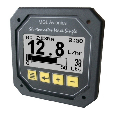
SAM is the industry’s first digital standby instrument to provide
attitude, altitude, airspeed, slip, vertical trend, and heading information
in an advanced, 2-inch format. The compact design and selectable
orientation (horizontal and vertical) ensures a perfect t within any
panel. The self-contained, rechargeable, emergency battery offers
pilots an increased level of safety. All backed by Mid-Continent’s
world-class reputation for high quality and responsive service.
J. Todd Winter
President and CEO
Mid-Continent Instruments and Avionics

REV. F Sept 15, 2015 Manual Number 9017846
FORWARD
This manual contains information regarding the use and interpretation
of information presented to the pilot and crew during normal and
emergency operation of SAM — the MD302 Standby Attitude Module.
Operational instructions are intended for persons who operate aircraft
in accordance with applicable Federal Aviation Regulations (Title 14 CFR).
We welcome your comments concerning our product and this manual.
When reporting a specic problem, please describe it briey and include
the manual part number, the paragraph or image number and page number.
Please e-mail or send comments and technical questions to:
Mid-Continent Instruments and Avionics
Attn: Technical Publications
9400 East 34th Street North
Wichita, Kansas 67226 USA
E-mail: [email protected]

TABLE OF CONTENTS
IMPORTANT:
Read this entire guide prior to operating SAM — the MD302
Standby Attitude Module — in flight.
PAGE
USER INTERFACE 1
PRE-FLIGHT MODE 2
FLIGHT MODE 3
Attitude Operation 4
Slip Operation 7
Heading Operation 8
Altitude Operation 10
Airspeed Operation 14
Menu Operation 17
OPTIONS MENU 18
ALT Units 19
BARO Units 20
Attitude Symbol 21
ATT Mask 22
ALT Trend 23
INFO 24
Review Conguration 25
Battery INFO 26
Exit Menu 27
Power OFF 28
Brightness Adjustment 29
EMERGENCY OPERATION 30
In Flight 30
On the Ground 32
ALERTS AND ANNUNCIATIONS 33
SERVICE REMINDER 35
PRODUCT SPECIFICATIONS 39
LIMITED WARRANTY 40
PRODUCT REGISTRATION 41

SAM is designed for simple and intuitive operation. The User Interface
provides quick interpretation of the ight information displayed.
The central Control Knob can be located at the bottom-center, middle-
left or middle-right of the unit bezel depending on the installation
orientation. This is the only user interface device on the unit.
The Control Knob has two functions: Push and Turn.
The Control Knob provides 16-detents per revolution and typically
changes the information it is controlling on the display one unit per
detent or click.
The Push function is used to select the highlighted option in a menu
or to enter and exit menus and control functions. The Push function
can also perform certain operations with a push-and-hold action.
USER INTERFACE
REV. F Sept 15, 2015 Manual Number 9017846 1

REV. F Sept 15, 2015 Manual Number 9017846
2
In Pre-ight Mode, power is applied to the unit and the Introduction
Screen appears during startup (Image 1).
During Pre-ight Mode, the Introduction Screen will be displayed
while the unit conducts an initial Power-up Built-in Test (PBIT) of
the system to validate operational readiness. This includes, among
others, a battery capacity measurement, an internal test to verify
software and memory, and conrmation that the internal settings
and identication of the unit match the Conguration Module
installed in the aircraft cable harness.
The Introduction Screen will be displayed for approximately ve
seconds and will transition to Flight Mode when complete.
PRE-FLIGHT MODE
PRE-FLIGHT MODE
INTRODUCTION SCREEN
Image 1

In Flight Mode, the
unit operates normally
by displaying six functions:
Attitude, Altitude,
Airspeed, Slip, Vertical
Trend, and Heading
Information (Images 2, 3).
FLIGHT MODE
FLIGHT MODE
HORIZONTAL ORIENTATION
Image 2
REV. F Sept 15, 2015 Manual Number 9017846 3
Image 3
FLIGHT MODE
VERTICAL ORIENTATION

Flight Mode / ATTITUDE OPERATION
REV. F Sept 15, 2015 Manual Number 9017846
4
The Attitude Indicator portion of the display (Image 4) will always
appear on the top display when oriented vertically and can be
congured to appear on the right or left display when oriented
horizontally.
The Attitude Indicator consists of seven parts: Horizon Line, Sky
(blue), Ground (brown), Symbolic Airplane, Roll Scale, Pitch Scale
and Slip Indicator.
The Symbolic Airplane will always remain in the center of the
display, with the background elements moving behind it to represent
the aircraft’s position relative to the horizon. The symbol that represents
the airplane can be selected during Flight Mode using the Options
Menu (see Options Menu, page 21).
The Roll Scale is depicted as an arc of graduations representing
bank angles of 0° (triangle), 10°, 20°, 30°, 45° (small triangle) and 60°.
The Roll Scale can be congured during installation to be xed to the
sky/horizon or xed to the top of the display. The unit is operable and
usable in a continuous and unlimited roll range of 360°+.
CAUTION: The roll conguration must be set to match other
attitude indicators in your panel.
The Roll Pointer is the triangle just below the Roll Scale and represents
the aircraft in relation to its bank angle. It is congured, by denition,
to operate conversely to the Roll Scale behavior. That is, a rotating
Roll Scale produces a xed Roll Pointer and a xed Roll Scale
produces a rotating Roll Pointer.
ATTITUDE OPERATION
Flight Mode / ATTITUDE OPERATION
REV. F Sept 15, 2015 Manual Number 9017846 5
Image 4
Roll/Bank Scale
Symbolic Airplane
Pitch Scale
Horizon Line
Slip Indicator
The Pitch Scale is depicted as a series of graduations representing
pitch angles every 5°, with every 10° graduation being wider and
numbered. The unit is operable and usable in a continuous and
unlimited pitch range of 360°+.

Flight Mode / ATTITUDE OPERATION
ATTITUDE OPERATION
This image demonstrates 50° pitch up and
18° left turn. Red chevrons point to the horizon line.
Image 5
REV. F Sept 15, 2015 Manual Number 9017846
6
30 30
6060
50
50
40
40
A series of chevrons (^) will appear overlaid on the Pitch Scale
at attitudes greater than ± 45°. This is to indicate to the pilot the
direction of the horizon for quick reference when in an unusual pitch
attitude (Image 5). The chevrons always point toward the horizon line.

The Slip Indicator portion of the display will appear at the bottom
of the Attitude Display (Image 5). If Heading Operation is enabled,
the Slip Indicator will appear to the left and above the Heading Window
in horizontal orientation, and directly above the Heading Window in
vertical orientation (Image 6).
The Slip Indicator is represented by a shaded translucent background
with two white lines around center and a white ball. When the ball is
maintained between the vertical lines during banking maneuvers, the
turn is considered “coordinated” without slip.
The Slip Indicator’s background becomes semi-transparent if the
Roll Scale or Roll Pointer pass behind the indicator. All other elements
remain visible.
Flight Mode / SLIP OPERATION
REV. F Sept 15, 2015 Manual Number 9017846 7

HEADING OPERATION
Flight Mode / HEADING OPERATION
Image 6
Roll/Bank Scale
Symbolic Airplane Heading Scale
Pitch Scale Horizon Line
Heading Window
Slip Indicator
Heading Operation can be congured during installation. The
heading information is comprised of a window showing the current
heading and a moving scale located along the bottom of the
display (Image 6). The Heading Scale is depicted as a series of
graduations every 10° with numbers every 30°, and letters for each
cardinal heading.
REV. F Sept 15, 2015 Manual Number 9017846
8

ARINC DATA LOSS
The Heading data is received directly from ARINC input and
displayed without reprocessing. If ARINC input data is lost,
the display will read “---” (Image 7).
Image 7
Flight Mode / HEADING OPERATION
REV. F Sept 15, 2015 Manual Number 9017846 9
ARINC data loss shown below.
HEADING OPERATION

Flight Mode / ALTITUDE OPERATION
The Altimeter Indicator portion of the display will always appear on
the bottom display when oriented vertically and can be congured
to appear on the right or left display when oriented horizontally
(Image 8).
The Altimeter consists of four parts: Altitude Window, Altitude
Scale, Barometric Setting Window and optional Altitude/Vertical
Trend Bar.
The Altitude Window displays the current, barometric corrected
altitude. The digits of the display are in increments of twenty and
the window is expanded over this portion of the number to display
a minimum spread of forty units. The numbers will ‘roll’ or scroll
to assist in quick reference to the increasing or decreasing nature
of the aircraft’s altitude. The hundreds, thousands and ten-thousands
digits appear to the left of the tens digits with the thousands and
ten-thousand digits slightly larger than the others. The Altitude Pointer
(triangle) to the right of the window points to the associated position
on the Altitude Scale of the current altitude. Altitude units of measure
appear below the Altitude Window and can be changed during Flight
Mode using the Options Menu (see Options Menu, page 19). The
pilot may select feet or meters.
The Altitude Scale is positioned vertically along the right margin of
the display. The current altitude is always in the middle of the scale
and indicated by the Altitude Pointer on the right side of the Altitude
Window. The scale has numeric indications every one-hundred units
with minor graduations every fty units and sub-graduations every
twenty-ve units. In horizontal installations, the scale spans
approximately 400 units from top to bottom. In vertical installations,
the scale spans approximately 500 units from top to bottom. The
scale will ‘roll’ or scroll to assist in quick reference to the increasing
REV. F Sept 15, 2015 Manual Number 9017846
10

Flight Mode / ALTITUDE OPERATION
REV. F Sept 15, 2015 Manual Number 9017846 11
Altitude display shown below.
ALTITUDE OPERATION
Image 8
Altitude Scale
Altitude/Vertical Trend Bar
Altitude
Window/Pointer
Altitude Units of Measure
Barometric Setting Window

REV. F Sept 15, 2015 Manual Number 9017846
12
Flight Mode / ALTITUDE OPERATION
or decreasing nature of the aircraft’s altitude. The Barometric
Window shows the currently set barometric pressure. It is identied
by the abbreviation BARO and is located at the top center of the
Airspeed/Altitude Display. Setting the current barometric pressure
compensates the altitude for the appropriate environmental conditions.
The barometric setting can be adjusted by turning the Control
Knob while in Flight Mode. When adjusting the barometric pressure
the digits will turn green (Image 9). When nished setting the pressure
the digits will return to their original color. Barometric pressure units
can be selected during Flight Mode using the Options Menu (see
Options Menu, page 20). Note: If the unit is installed to receive
ARINC data from the Primary Flight Display (PFD), the BARO value
will automatically synchronize. When the two are synchronized two
arrows will appear on either side of BARO (Image 10). Manually
changing the MD302 barometric setting will override the external
source.
The Altitude Trend Bar is located along the right margin of the Altitude
Display. This feature can be turned ON or OFF using the Options Menu
(see Options Menu, page 23). The Altitude Trend Bar is magenta in
color and originates at the current altitude on the Altitude Scale —
always from the middle of the display, directly across from the Altitude
Pointer. The height of the Trend Bar, above or below the current
altitude, indicates the altitude of the aircraft on the Altitude Scale if
the current vertical speed or ‘altitude trend’ is maintained over a
period of six seconds. For example, as seen in Image 9, the current
altitude is approximately 2,420 feet. The Trend Bar is at approximately
2,470 feet, indicating that the aircraft’s altitude will be 2,470 feet in six
seconds if the current vertical speed or climb is maintained constant.
The length of the Trend Bar will increase with increased dive or climb
rates and approach zero or disappear entirely as the vertical speed
reaches zero in level ight.

Flight Mode / ALTITUDE OPERATION
REV. F Sept 15, 2015 Manual Number 9017846 13
Image 10
Two arrows appear on either side of BARO when synronized.
Image 9
The Barometric Setting will turn green during adjustment.

REV. F Sept 15, 2015 Manual Number 9017846
14
Flight Mode / AIRSPEED OPERATION
The Airspeed Indicator portion of the display will always appear on
the bottom display when oriented vertically and can be congured
to appear on the right or left display when oriented horizontally
(Image 11).
The Airspeed Indicator Display consists of three parts: Airspeed
Window, Airspeed Scale and Airspeed Limitations or Range
Markings.
The Airspeed Window displays the current Indicated Airspeed (IAS).
The digits of the display are enlarged for visibility and increment by
one unit. The units will ‘roll’ or scroll to assist in quick reference
as to the increasing or decreasing nature of the aircraft’s airspeed.
The Airspeed Pointer (triangle) to the left of the window points to
the associated position on the Airspeed Scale of the current airspeed.
Airspeed units are available in Knots, KPH (kilometers per hour) or
MPH (miles per hour). The unit of measure appears below the airspeed
window and can be selected during installation in the Conguration
Mode only. This selection is not available in Flight Mode.
The Airspeed Scale is positioned vertically along the left margin of
the display. The current airspeed is always in the middle of the
scale and indicated by the Airspeed Pointer on the left side of the
Airspeed Window. The Airspeed Scale has numeric indications every
ten or twenty units depending on the unit of measure selected. Minor
graduations appear every ve or ten units, respectively. In horizontal
installations, the scale spans approximately 50 or 100 units from top
to bottom, depending on the unit of measure. In vertical installations,
the scale spans approximately 80 or 160 units from top to bottom,
depending on the unit of measure. The Airspeed Scale will ‘roll’ or
scroll to assist in quick reference as to the increasing or decreasing
nature of the aircraft’s airspeed.

Flight Mode / AIRSPEED OPERATION
Image 11
Range Markings
Airspeed Scale
Airspeed
Window/Pointer
Airspeed Units
Airspeed display shown below.
AIRSPEED OPERATION
REV. F Sept 15, 2015 Manual Number 9017846 15

Flight Mode / AIRSPEED OPERATION
The Airspeed Limitations, also known as “V-speeds” or Range
Marks, are indicated with colored range marking bands placed
vertically along the left margin next to the Airspeed Scale. The colors
and values of each bar can be set during installation in Conguration
Mode by the installer only. This setting is not available in Flight Mode.
Colors must be selected based on industry-dened colors and
V-speed limits as dened by the aircraft’s specic Pilot’s Operating
Handbook (POH). Range markings are represented by full-width
bars, half-width bars and/or radial marks. A traditional ‘barber pole’
or ‘barber pole’ radial may also be displayed if the aircraft requires
and provides the appropriate Vne, Vmo and/or Mmo values.
REV. F Sept 15, 2015 Manual Number 9017846
16
Table of contents