Middleby CTX GEMINI Series Operation manual
DZ33I, English
OWNER’S OPERATING
&
INSTALLATION
MANUAL
CTX GEMINI SERIES OVENS
DZ33I
CTX
®
1400 Toastmaster Drive
Elgin, IL, USA 60120
847-741-3300
A Middleby Company
www.middleby.com
Part No. 69982
Revision: B • 4/11/2018
Model No._________________Serial No.__________________________Installation Date________

2
CTX®
NO QUIBBLE LIMITED WARRANTY
(U.S.A ONLY)
MIDDLEBY MARSHALL HEREINAFTER REFERRED TO AS THE SELLER, WARRANTS
EQUIPMENT MANUFACTURED BY IT TO BE FREE FROM DEFECTS IN MATERIAL AND
WORKMANSHIP FOR WHICH IT IS RESPONSIBLE. THE SELLER’S OBLIGATRION UNDER THIS
WARRANTY SHALL BE LIIIMITED TO REPLACING OR REPAIRING AT SELLER’S OPTION,
WITHOUT CHARGE, ANY PART FOUND TO BE DEFECTIVE AND ANY LABOR AND MATERIAL
EXPENSE INCURRED BY SELLER IN REPAIRING OR REPLACING SUCH PART, SUCH
WARRANTY SHALL BE LIMITED TO THE ORIGINAL PURCHASER ONLY AND SHALL BE
EFFECTIVE FOR A PERIOD OF ONE YEAR FROM DATE OF ORIGINAL INSTALLATION, OR 18
MONTHS FROM DATE OF SHIPMENT, WHICHEVER IS EARLIER; PROVIDED THAT TERMS OF
PAYMENT HAVE BEEN FULLY MET.
This warranty is valid only if the equipment is installed, started and demonstrated under the
supervision of a factory certified installer.
Abuse, acts of God, belt jams, cleaning, customer abuse, insufficient utilities, maintenance, non-oven
related issues, preventative maintenance, or normal maintenance function including adjustment of
airflow, heaters, conveyor components, door mechanisms, microswitches, thermostatic controls, and
replacement of bushings, light bulbs, circuit breakers, fuses, indicating lights and wear points, are not
covered by this no quibble limited warranty.
Seller shall be responsible only for repairs or replacements of defective parts performed by Seller’s
authorized service personnel. Authorized service agencies are located in principal cities throughout
the contiguous United States, Alaska and Hawaii. This warranty is valid in the 50 United States and is
void elsewhere unless the product is purchased through Middleby International with warranty
included.
The foregoing warranty is exclusive and in lieu of all other warranties, expressed or implied.
There are no implied warranties of merchantability or of fitness of a particular purpose.
The foregoing warranty shall be Seller’s sole and exclusive obligation and Buyer’s sole and exclusive
remedy for any action including breach of contract or negligence. In no event shall Seller be liable for
a sum in excess of the purchase price of the item. Seller shall not be liable for any prospective or lost
profits of Buyer.
CTX® 1400 Toastmaster Drive Elgin, IL 60120 USA (847) 741-3300
©2018 CTX www.middleby-marshall.com

3
NOTICE:
This Operating and Installation Manual should be given to the user. The operator of the oven
should be familiar with the functions and operation of the oven.
This manual must be kept in a prominent, easily reachable location near the oven.
It is suggested to obtain a service contract with a manufactures certified service agent.
NOTICE
CONTACT YOUR LOCAL SERVICE COMPANY TO PERFORM MAINTENANCE AND REPAIRS.
A SERVICE AGENT DIRECTORY IS SUPPLIED IN YOUR
INSTALLATION KIT.
NOTICE
Using any parts other than genuine
CTX factory
manufactured parts relieves the manufacturer
of all warranty and liability.
NOTICE
CTX (Manufacturer) reserves the right to
change specifications at any time.
WARNING
The equipment warranty is not valid unless the oven is installed, started and demonstrated under the
supervision of a factory certified installer.
FOR YOUR SAFETY
DO NOT STORE OR USE GASOLINE OR OTHER
FLAMMABLE VAPORS AND LIQUIDS IN THE
VICINTIY OF THIS OR ANY OTHER APPLIANCE
WARNING
Improper installation, adjustment, alteration,
service or maintenance can cause property damage,
injury or death. Read the installation, operating and
maintenance instructions thoroughly before installing
or servicing this equipment.

4
TABLE OF CONTENTS
SECTION 1- DESCRIPTION …………………………………………………… 5
A. Component Location………………………………………………..........6
B. Component Function……………………………………………………...7
C. Oven Specifications……………………………………………………….8
D. Dimension Drawings…………………………………………………..9-11
SECTION 2- INSTALLATION ………………………………………………….12
A. Inspect For Shipping Damage………………………………………….12
B. Placement of Oven………………………………………………………12
C. Items for Stacking Oven………………………………………………...12
D. Base Section Assembly……………………………………………..12-14
E. Mounting Single Oven Onto Base Assembly……………………..14-15
F. Stacking and Mounting Two Ovens……………………………………15
G. Stacking and Mounting Three Ovens……………………………........15
H. Stacking and Mounting Four Ovens…………………………………...15
I. Electrical Connection ……………………………………………………16
J. “Loose” Parts……………………………………………………………..16
SECTION 3- OPERATION ……………………………………………………..17
A. Location of Controls……………………………………………………..17
B. MenuSelect™ Control Operation and Programming…………….18-27
C. Cooking in a CTX Oven……………………………………………..28-29
D. Time and Temperature Guide.……………………………………..30-36
SECTION 4- CLEANINING .........................................................................37
A. Cleaning the Cooling Fan Filter………………………………………...37
B. Oven Cleaning Operation…………………………………...………37-38
C. Cleaning “Loose” Parts………………………………………………….38
D. Cleaning the Exterior………………………………………………...….38
SECTION 5- MAINTENANCE & TROUBLESHOOTING …………….….....39
A. Chart 1- Error Messages…………...…………………………………...39
B. Chart 2- Troubleshooting………………………………………………..40
SECTION 6- PARTS LISTS – Key Spare Part List ………………………… 41
Oven Open Rear View………………………………………………………42
Oven Elements Exposed View……………………………………………..43
Oven Front Closed View…………………………………………………….44
Oven Front Open View………………………………………………………45
Single Belt Conveyor……………………………………………………..46-47
Split Belt Conveyor ………………………………………………………48-49
Hearth Belt Conveyor……………………………………………..………50-51
SECTION 7- ELECTRICAL SCHEMATICS……………………………...…..52
A. EMS & Hi-Temp Voltage & Amperage Schedule ……………………52
B. Model DZ33I, 208/230V, 3Ph Schematic……………………………..53
C. Model DZ33I, 208/240V, 3Ph to 1Ph Conversion Schematic….……54
D. Model DZ33I, 380/415V, 3Ph Schematic…………...………………...55
E. Model DZ33I, 230V, CE, 3Ph Schematic……………………………..56
F. Model DZ33I, 380V, CE, 3Ph Schematic……………………………..57

5
SECTION 1 - DESCRIPTION
CTX Series oven is:
• Electrically powered • Conveyorized
• Zone heated by infrared panels • Electronically controlled
CTX Oven Model:
• DZ33I – 31” (787 mm) long cooking chamber with a MenuSelect™ control.
NOTE: “DZ” designation on ovens stands for: “DZ” = Duel Zone Temperature Control.
Figure 1 DZ33I
This manual must be kept for future reference
Note:
Wiring diagrams are contained in this manual
and are also located in the oven.

6
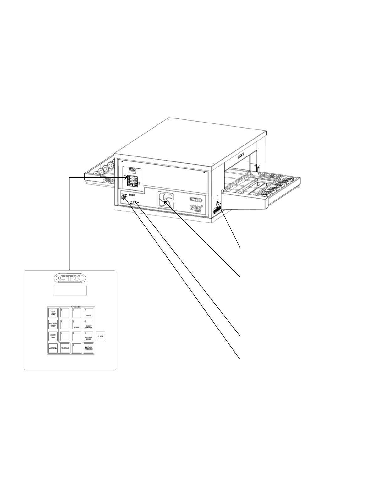
A. Component Location
OvenDataPlate
Figure 1-2
Locking Casters
Oven Base
with Legs
Control Circuit
Breakers
Cooling Fan
On/Off Switch
Conveyor
Control with Digital Display
Draft Curtain
Conveyor Belt
Or Belts
Crumb Tray
Cooking
Chamber
Conve
y
or Motor
Fan Warnin
g
Li
g
ht

7
B. Component Function
1. Oven Controller
The controller controls all functions of the oven. The cooking temperatures can be set from 200F
to 900F (93C to 509C). Cooking times (conveyor speed) can be set from 1:00 minute to 60:00
minutes on the DZ33I.
Controller features a self-cleaning mode, an energy conserving standby mode, and also included
is a service mode designed to assist the service technician.
The Menu Select control contains 10 menu keys which can be preset to control both oven
temperature and cook time. The operator must then press only the menu key for the desired
product being cooked.
2. Infrared Heating Panels
Heating panels are positioned above and below the conveyor belt in the oven chamber
(figure 1-3). When energized these panels emit infrared long waves. These waves do not heat the
air through which they pass. Instead the waves are absorbed by the outer surface of the product
transported through the oven on the conveyor belt. Using this application, food is placed on the
conveyor and the unique properties of the infrared waves cause it to cook from the outside to the
center in traditional fashion.
Figure 1-3
DZ33I Heat Zones
3. Conveyor
The conveyor is used to convey the product through the oven deck (chamber). The conveyor is
made up of 1 to 2 stainless steel wire belts which can travel in either direction around the frame.
The conveyor is controlled by the controller and can travel at speeds from 1:00 to 60:00 minutes.
The speed of the conveyor determines how long the product will be in the cooking chamber which
is the cooking time.
CAUTION: All DZ ovens are Voltage Specific. Check the oven data plate for the voltage. Applying the wrong voltage can
immediately damage the oven. Refer to the Installation Section of this manual for complete instructions before installing
an oven.

8
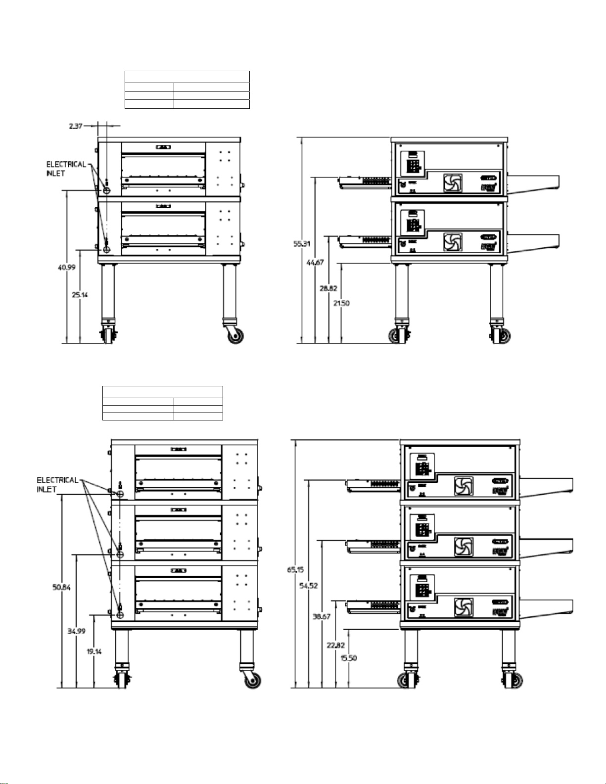
C. Oven Specifications
Figure 1-1 Dimensions DZ33I
Single Oven on Base and Casters
Overall Height 39.44” (1001.8mm)
Overall Depth 39.03” (991.4mm)
Overall Length 59.00” (1499mm)
Double Oven on Base and Casters
Overall Height 55.32” (1328.9mm)
Overall Depth 39.03” (991.4mm)
Overall Length 59.00” (1499mm)
Triple Oven on Base and Casters
Overall Height 65.17” (1655.3mm)
Overall Depth 39.03” (991.4mm)
Overall Length 59.00” (1499mm)
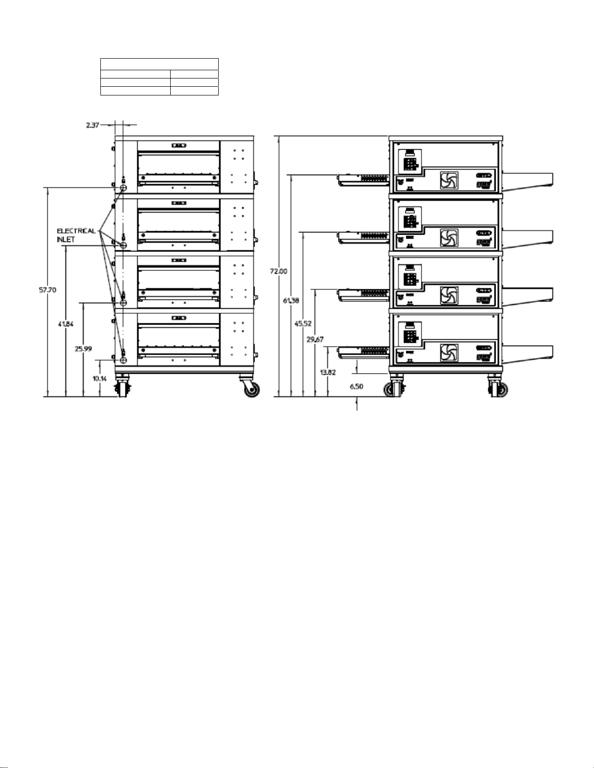
Quad Oven on Base and Casters
Overall Height 72.02” (1829.3mm)
Overall Depth 39.03” (991.4mm)
Overall Height 59.00” (1499mm)
Oven Chamber Dimensions
Overall Height 5.5” (140mm)
Overall Width 22.25” (565mm)
Overall Length (Heating Zone) 31.22” (793mm)
Conveyor Baking Area 3.88sq. ft. (0.36sq. m.)
Stainless Steel Single Conveyor Belt Width 18” (457mm)
Stainless Steel Duel Conveyor Belt Width (2) 8.00” (203mm)
Net Weight of Single Unit 362 lbs. (164.2 kg)
Temperature Range 1500F-9000F (66.50C-4820C)
Oven Electrical Specification Chart
NOTE: A separate ground wire must be supplied with each oven; conduit may not be used as a ground.
NOTE: Supply wire must be rated minimum 900C (1940F).
Domestic Amp Loading Charts
DZ33I Domestic
Model
No AC
Volts Phase Hz Connected
kW AVG
Operating
kW
Connected Load (Amps) Required
Breaker
(Amps)
L1 L2 L3 N
DZ33I 208 1 50/60 8.95 3.1 45.7 45.7 -- -- 60
DZ33I 208 3 50/60 9.5 3.1 30.3 30.3 19.8 -- 40
DZ33I 240 1 50/60 10.0 3.1 41.7 41.7 -- -- 60
DZ33I 240 3 50/60 10.0 3.1 27.6 27.6 18.1 -- 40
DZ33I International
Model
No AC
Volts Phase Hz Connected
kW AVG
Operating
kW
Connected Load (Amps) Required
Breaker
(Amps)
L1 L2 L3 N
DZ33I
(CE Listed) 230 3 50/60 9.2 3.1 26.4 26.4 17.3 - 40
DZ33I
(CE Listed) 380 3 50/60 8.4 3.1 18.9 9.2 9.2 8.9 30

9
D. Dimension Drawings
1. Dimension drawing of Single DZ33I Oven on Base.
Minimum Clearance
Rear 0”
Left 4”
Right 4”
CTX reserves the right to change specifications and
product design without notice. Such revisions do not
entitle the buyer to corresponding changes,
improvements, additions or replacements for
previously purchased equipment.
Side View Front View
10
2. Dimension drawing of two stacked DZ33I ovens on base.
Minimum Clearance
Rear 0”
Left 4”
Right 4”
3. Dimension drawing of three stacked DZ33I ovens on base.
Minimum Clearance
Rea
r
0”
Left 4”
Right 4”
11
4. Dimension drawing of a Quad stacked DZ33I ovens on base.
Minimum Clearance
Rear 0”
Left 4”
Right 4”
Side View Front View

12
SECTION 2 – INSTALLATION
A. Inspect for shipping Damage
All shipping container should be examined for
damage before and during unloading. This
equipment was carefully inspected and
packaged at the factory. The freight carrier has
assumed responsibility for its safe transit and
delivery. If equipment is received in damaged
condition, either apparent or concealed, a
claim must be made with the delivering
carrier.
1. Apparent Damage or Loss- If damage or loss is
apparent it must be noted on the freight bill or
express receipt at the time of delivery, and it
must be signed by the carrier’s agent (driver). If
this is not done, the carrier may refuse the claim.
The carrier will supply the necessary claim
forms.
2. Concealed Damage or Loss- If damage or loss
is not apparent until after equipment is uncrated,
a request for inspection of concealed damage
must be made with carrier within 10 days. The
carrier will make an inspection and will supply
necessary claim forms. Be certain to retain all
contents plus external and internal
packaging/crating materials for inspection.
B. Placement of Oven
Some very important considerations must be
made when choosing the place where the oven
is to operate.
1. This oven is conveyorized and operates
continuously. It should be placed so it fits into
the “flow” of the operation.
2. Drafts entering the oven chambers can cause
inconsistent cooking results. Check the area
surrounding the oven and eliminate sources of
drafts such as open windows or doors and fans
or other appliances that cause air circulation.
3. Oven should be positioned so hot air from
another piece of equipment cannot enter the
oven cooling fan air intake on the oven front.
Serious problems could occur.
NOTE: To validate a new oven(s) warranty, an
authorized CTX installer must supervise Steps C
through H of installation.
C. Items for Stacking Oven
The following items are required for stacking
ovens:
Quantity Description
2 4”x4”x4’ (10.2cm x 10.2cm x 61cm)
board
2 4”x4”x2’ (10.2cm x 10.2cm x 122cm)
board (stacking ovens only)
2 1-1/2”x7’ (3.8cm x 213cm) rigid pipe
Schedule 40
2 Custom M5 Lift (Vermette)
D. Base Section Assembly
1. Locate the carton containing the oven base.
Remove and inventory the contents. Refer to the
correct parts lists below and also to Figure 2-1
2. Lay weldment base (Item 4, Figure 2-1) upside
down on the floor and remove the protective film
from base. Attach the four Assy. Leg, Caster
(Item 5) using 16 SCR, Cap HX HD 3/8”-16X1”
NP (Item 10), 16 Washer, Flat SS 3/8” (Item 9),
and 16 Washer, Lock Split 3/8” ZP (Item 8). For
Quad screw casters directly into basepad.
3. Turn the base assembly upright and set aside.
Also set aside 4 SCR, SL Truss HD SS 10-
32X1-1/2” (Item 7), and Panel, Top (Item 5). The
base will be used to stack oven on, and the top
secures to the top of the oven top oven.

13
Figure 2-1
Single Oven Stand Parts
Item Qty, Part Number Description
1 1 67880 INSUL, BASE PART A
2 2 67881 INSUL, BASE PART C
3 2 67882 INSUL, BASE PART B
PARTS LISTED ABOVE ARE FROM 69978 KIT, DZ33I INSULATION
4 1 67884 WLDMT. BASE DZ33
5 1 67614 PANEL, TOP
6 4 66948 ASSY. LEG, CASTER
7 4 59156 SCR, SL TRUSS HD SS 10-32X1-1/2”
8 16 21422-0001 WASHER, LOCK SPLIT 3/8” ZP
9 16 21416-0001 WASHER, FLAT SS 3/8”
10 16 2000531 SCR, CAP HX HD 3/8”-16X1” NP
Double Oven Stand Parts
Qty, Part Number Description
1 1 67880 INSUL, BASE PART A
2 2 67881 INSUL, BASE PART C
3 2 67882 INSUL, BASE PART B
PARTS LISTED ABOVE ARE FROM 69978 KIT, DZ33I INSULATION
4 1 67884 WLDMT. BASE DZ33
5 1 67614 PANEL, TOP
6 4 66948 ASSY. LEG, CASTER
7 4 59156 SCR, SL TRUSS HD SS 10-32X1-1/2”
8 16 21422-0001 WASHER, LOCK SPLIT 3/8” ZP
9 16 21416-0001 WASHER, FLAT SS 3/8”
10 16 2000531 SCR, CAP HX HD 3/8”-16X1” NP
14
Triple Oven Stand Parts
Item Qty, Part Number Description
1 1 67880 INSUL, BASE PART A
2 2 67881 INSUL, BASE PART C
3 2 67882 INSUL, BASE PART B
PARTS LISTED ABOVE ARE FROM 69978 KIT, DZ33I INSULATION
4 1 67884 WLDMT. BASE DZ33
5 1 67614 PANEL, TOP
6 4 66947 ASSY. LEG, CASTER
7 4 59156 SCR, SL TRUSS HD SS 10-32X1-1/2”
8 16 21422-0001 WASHER, LOCK SPLIT 3/8” ZP
9 16 21416-0001 WASHER, FLAT SS 3/8”
10 16 2000531 SCR, CAP HX HD 3/8”-16X1” NP
Quad Oven Stand Parts
Item Qty, Part Number Description
1 1 67880 INSUL, BASE PART A
2 2 67881 INSUL, BASE PART C
3 2 67882 INSUL, BASE PART B
PARTS LISTED ABOVE ARE FROM 69978 KIT, DZ33I INSULATION
4 1 67884 WLDMT. BASE DZ33
5 1 67614 PANEL, TOP
11 4 58930 CASTER
-- 4 59156 SS Truss Head Screw, 10-32x1-½
E. Mounting Single Oven onto Base
Assembly
1. Cut the bands holding the protective shipping
carton to the skid. Carefully remove the bands and
lift the carton up off the oven.
2. Cut the bands holding the oven to the skid.
3. Slide the two 4”X4”X10’ (10.2cm X 10.2cm X
304.8cm) pieces of wood through the oven cavity.
The wood pieces should be sticking out of the
oven equally on both sides. One of the pieces of
wood should be placed to the rear of the oven and
the other in the front of the oven. See figure 2-2.
4. Position the two Vermette lifts on either ends of
the oven under the 10’ (304.8cm) pieces of wood,
making sure the legs with wheels are up as close
as possible to the skid. Place the two 4”X4”X4’
(10.2cm X 10.2cm X 122cm) pieces of wood
across the two Vermette forks, at least 6”
(182.88cm) in from the end of the forks, and
centered with the 10’ (304.8cm) pieces of wood
running through the oven cavity. See figure 2-2.
IMPORTANT: Lift the oven with the
4”X4”X10’ (10.2cmX10.2cmX122cm)
running through the oven only. DO
NOT lift the oven by the conveyor.
Damage WILL result.
5. With the 4’ (122cm) pieces positioned under the
10’ (304.8cm) begin to lift the oven with the two
Vermette lifts.
(keeping the oven level at all times).
6. When the oven is completely free from the skid,
slide it out from under the oven. (dispose of the
skid in accordance with local regulations).
7. Lift the oven high enough to position the stand
under. Roll the stand under the oven (do not roll
the oven and lifts over the stand) and lower onto
the stand.
The bottom of the oven will wrap around the stand.
(careful not to get hands or fingers
between oven and stand).

15
Figure 2-2
F. Stacking and Mounting Two Ovens
1. Cut the bands holding the protective
shipping carton to the skid. Carefully
remove the bands and lift the carton up
off the oven.
2. Cut the bands holding the oven to the
skid.
3. Slide the two 4”X4”X10’ (10.2cm X
10.2cm X 304.8cm) pieces of wood
through the oven cavity. The wood
pieces should be sticking out of the
oven equally on both sides. One of the
pieces of wood should be placed to the
rear of the oven and the other in the
front of the oven. See figure 2-2.
4. Position the two Vermette lifts on either
ends of the oven under the 10’
(304.8cm) pieces of wood, making sure
the legs with wheels are up as close as
possible to the skid. Place the two
4”X4”X4’ (10.2cm X 10.2cm X 122cm)
pieces of wood across the two Vermette
lift forks, at least 6” (182.88cm) in from
the end of the forks, and centered with
the 10’ (304.8cm) pieces of wood
running through the oven cavity.
(figure 2-2)
IMPORTANT: Lift the oven with the
4”X4”X10’ (10.2cmX10.2cmX122cm)
running through the oven only. DO
NOT lift the oven by the conveyor.
Damage WILL result.
5. With the 4’ (122cm) pieces positioned
under the 10’ (304.8cm) begin to lift the
oven with the two Vermette lifts (keeping
the oven level at all times).
6. When the oven is completely free from
the skid, slide it out from under the
oven. (dispose of the skid in accordance
with local regulations).
7. Elevate the upper oven high enough to
position the lower oven underneath.
8. Roll the stand with the lower oven under
the upper oven (do not roll the oven
and lifts over the lower oven) and lower
onto the lower oven. The bottom of the
oven will wrap around the top of the
lower oven.
(careful not to get hands or fingers
between ovens).
G. Stacking and Mounting Three Ovens
1. Follow the previous procedures in step
F.
(careful not to get hands or fingers
between ovens).
IMPORTANT: Lift the oven with the
4”X4”X10’ (10.2cmX10.2cmX122cm)
running through the oven cavity only.
DO NOT lift the oven by the conveyor.
Damage WILL result.
H. Stacking and Mounting Four Ovens
1. Follow the previous procedures in step
F.
(careful not to get hands or fingers
between ovens).
IMPORTANT: Lift the oven with the
4”X4”X10’ (10.2cmX10.2cmX122cm)
running through the oven cavity only.
DO NOT lift the oven by the conveyor.
Damage WILL result.

16
I. Electrical Connection
All wiring and electrical connections required
for the oven(s) must be performed by a
certified electrician. Each oven must be wired
according to the electrical specification for the
oven rating. See charts in Section 1, electrical
schematic in Section 7 and schematics
furnished with the oven. A separate ground wire
must be supplied with each oven. Conduit may
not be used as ground. Consult national or local
electrical codes for wire gauge and circuit
breaker ratings.
CAUTION: All DZ Series Ovens are manufactured
for voltage specific operation.
IMPORTANT: ALWAYS carefully check the data
plate voltage rating to be sure which voltage to apply
when installing a DZ Series oven. Applying the
wrong voltage can immediately damage oven.
If local codes allow, we recommend that flexible
conduit be used for final connection as the oven
assembly is on casters and the use of flexible
conduit will allow movement for cleaning.
J. Loose Parts
The aluminum crumb trays (PN 67932) (2 per
oven) are shipped mounted in place. They are
removable for cleaning and are considered
loose parts. They should be checked prior to
startup to be sure they are properly in place.
The stainless steel draft curtain and exit
shelves are packed in a separate carton inside
oven.
NOTE: Make sure protective plastic film is removed
from draft curtains before installation.
1. Draft Curtains, stainless steel (PN
322904) (2 per oven). These mount above
the conveyor at the ends of the cooking
chamber. They serve to reduce drafts
through the oven chamber and to reduce
heat loss to the environment. To install,
locate the thin rod above each entrance/exit
of the oven. Hang one draft curtain over
each rod. They are in their lowest position
when hanging vertical. To raise the curtains
to their highest position, swing them outward
until they are horizontal and then push in
toward oven chamber.
NOTE: Make sure protective plastic film is
removed from exit shelves before installation.
2. Exit Shelves, stainless steel (PN
69776) (2 per oven). These shelves
mount in cantilever fashion at the exit
and entrance end of the conveyor and
provide a landing zone for cooked
product. Depending on the operation
they may or may not be needed or used.
To install, place the slotted end of the
shelf over the crossbar at the end of the
conveyor extension frame.
17
SECTION 3 – OPERATION
A. LOCATION OF CONTROLS
1. Operation Controls
The following information provides a basic description of the oven’s controls, their locations and the
functions they perform. It is necessary that the operator be familiar with them.
Fan Warning Light: The light will
illuminate when inside control compartment
Reaches130°F (54.4°C).
Cooling Fan, Grille and Filter: Air is
drawn through the grille and foam filter by a
24 volt DC cooling fan located immediately
behind. The fan circulates air throughout
the entire electrical raceway to cool the
front panel, top panel, and the electrical
components.
Circuit Breakers: (3 amp) Provides
overload protection for the control circuit.
On/Off Switch: Turns oven on or off.
Figure 3-1
Operating Controls

18
B. MenuSelect™ CONTROL OPERATION AND PROGRAMMING
1. Function of Controls
The oven operating controls are located to the left of the stainless steel front panel. The control panel
consists of an ON/OFF switch, a keypad with multi-function keys, and a vacuum tube florescent display.
The letter callouts in Figure 3-4 coincide with the following list which explains the keypad.
Figure 3-4
Control Panel

19
The following information provides a basic description of the oven controls,
their location upon the key-pad, and the function they perform.
Refer to Figure 3-4
B. TOP TEMPERATURE
Used to change set temperature of the top zone(s) during programming.
C. BOTTOM TEMPERATURE
Used to change set temperature of the bottom zone(s) during programming
D. COOK TIME
Used to display and/or change cook time set point of a preset menu.
E. ACTUAL
Used to briefly display actual temperature of all 4 zones for about 3 to 4 seconds.
F. Preset Menu Keys 0-9
Used to operate or program oven in one of ten preset menu modes.
NOTE: In the event of a power failure the oven will default back to the previously used preset menu when power is
restored. Always check that the oven is in the desired mode when the power is restored.
G. MANUAL OVERRIDE
Used to override preset menu setting and operate oven at any desired temperature and cook time.
H. CLEAN
Used to enter the self- cleaning mode of oven operation.
I. FEATURE
Used to initiate features. Pressed previous to entering a feature (TIMER, FORCE, CLOCK, STDBY/RESUME or
SERVICE CODES).
K. FORCE
Used to take the oven out of cleaning mode.
L. CLOCK
Used to set the oven clock
M. STDBY/RESUME
Used to enter and exit 25% reduced power standby mode.
N. SERVICE CODES
Used to access service modes.
O. Display. Provides readout of data including:
Data being entered
Error and service information
Set and actual temperatures
Set cook times
Oven status

20
1. OPERATION of the DZ33I MenuSelect™ Oven Controls
a. Turn Oven Deck ON
1. Turn ON main disconnect switch at the wall box.
2. Turn oven ON/OFF switch ON.
3. The display will automatically scroll through six (6) screens.
See below for the screen order.
Repeat scroll
b. Preset Menu Select Operation
Step Press Key Display Reads
The preset menu that was being
used when the oven was turned
OFF.
1. Press desired preset menu #
Oven deck is ready for cooking
when “READY” is displayed
c. View Actual Temperatures in all 4 zones
NOTE: To view the actual temperature the ACTUAL key must be pressed while the P: # is displayed.
Step Press Key Display Reads
Ready=Ovenatsettemperature
Heating = Oven heating up to set temperature
Cooling = Oven cooling down to set temperature
1. Push ACTUAL key
After approximately 3 to 4 seconds the display
reverts to the original program screen
This manual suits for next models
1
Table of contents
Other Middleby Oven manuals


