Middleby CTX G-26 Operation manual

OWNER'S
OPERATING
&
installation
manual
G-26
CONVEYOR
OVEN
CTO®
•
1400
Toastmaster
A
Middle
by
Company
®
<§•
Drive
•
Elgin,
IL
60120
•
(708)741-3300
•
FAX
(708)741-0015
Middleby
Corporation
24
Hour
Sorv,ce
Hotline
1-800-2384)444
*
K

CTX®
OVEN
LIMITED
WARRANTY
The
seller
warrants
equipment
manufactured
by
it
to
be
free
from
defects
in
material
and
workmanship
for
which
it
is
responsible.
The
Seller's
obligation
under
this
warranty
shall
be
limited
to
replacing
or
repairing
at
Seller's
option,
without
charge,
F.O.B.
Seller's
factory,
any
part
found
to
be
defective
and
any
labor
and
material
expense
incurred
by
Seller
in
repairing
or
replacing
such
part,
such
warranty
to
be
limited
to
a
period
of
one
(1)
year
from
date
of
original
installation
or
eighteen
(18)
months
from
date
of
shipment
from
Seller's
factory,
whichever
is
earlier,
provided
that
terms
of
payment
have
been
fully
met.
All
labor
shall
be
performed
during
regular
working
hours.
Overtime
premium
will
be
charged
to
the
Buyer.
THIS
WARRANTY
IS
NOT
VALID
UNLESS
EQUIPMENT
IS
STARTED
AND
DEMONSTRATED
UNDER
THE
SUPERVISION
OF
A
FACTORY
CERTIFIED
INSTALLER.
Normal
maintenance
functions,
including
lubrication,
thermostat
calibration,
and
replacement
of
light
bulbs,
fuses
and
indicating
lights,
are
not
covered
by
warranty.
Any
repairs
or
replacements
of
defective
parts
shall
be
performed
by
Seller's
authorized
service
personnel.
Seller
shall
not
be
responsible
for
any
costs
incurred
if
the
work
is
performed
by
other
than
Seller's
authorized
service
personnel.
When
returning
any
part
underwarranty,
the
part
must
be
intact
and
complete,
without
evidence
of
misuse
or
abuse,
freight
prepaid.
This
warranty
is
made
to
the
original
purchaser/user
and
is
not
transferable.
Seller
shall
not
be
liable
for
consequential
damages
of
any
kind
which
occur
during
the
course
of
installation
of
equipment,
or
which
result
from
the
use
or
misuse
by
Buyer,
its
employees
or
others
of
the
equipment
supplied
hereunder,
and
Buyer's
sole
and
exclusive
remedy
against
Seller
for
any
breach
of
the
foregoing
warranty
or
otherwise
shall
be
for
the
repair
or
replacement
of
the
equipment
or
parts
thereof
affected
by
such
breach.
The
foregoing
warranty
shall
be
valid
and
binding
upon
Seiler
if
and
only
if
Buyer
loads,
operates
and
maintains
the
equipment
supplied
hereunder
in
accordance
with
the
instruction
manual
provided
to
Buyer.
Seller
does
not
guarantee
the
process
of
manufacture
by
Buyer
or
the
quality
of
product
to
be
produced
by
the
equipment
supplied
hereunder
and
Seller
shall
not
be
liable
for
any
prospective
or
lost
profits
of
Buyer.
THE
FOREGOING
WARRANTY
IS
EXCLUSIVE
AND
IN
LIEU
OF
ALL
OTHER
EXPRESS
AND
IMPLIED
WARRANTIES
WHATSOEVER.
SPECIFICALLY
THERE
ARE-NO
IMPLIED
WARRANTIES
OF
MERCHANTABILITY
OR
OF
FITNESS
FOR
A
PARTICULAR
PURPOSE.
The
foregoing
shall
be
Seller's
sole
and
exclusive
obligation
and
Buyer's
sole
and
exclusive
remedy
for
any
action,
whether
in
breach
of
contract
or
negligence.
In
no
event
shall
seller
be
liable
for
a
sum
in
excess
of
the
purchase
price
of
the
item.
©1993
CTX
CTX®
•
1400
Toastmaster
Dr.
•
Elgin,
IL
60120-9272
•
(708)
741-3300
•
FAX
(708)
741-0015
i

retain
this
manual
for
future
reference
be
™
S
"
»
^SSSSS
FOR
YOUR
SAFETY
■
-
S
iSa,
NOTICE
Using
any
parts
other
than
[
genuine
CTX
factory
manufactured
parts
relieves
the
manufacturer
of
all
liability.
notice
#=sss.
the
buyer
to
corresponding
changes
im
provements,
additions
or
replacement
previously
purchased
equipment.
TABLE
OF
CONTENTS
SECTION
1
DESCRIPTION
.
1
A.
Component
Location.2
B.
Component
Function.
3
.4
C.
Oven
Specifications.
5
-6
D.
Dimension
Drawings.
7
SECTION
2
INSTALLATION
.
9
A.
Inspect
For
Shipping
Damage.
9
B.
Placement
of
Oven.
9
C.
Unpacking
Oven.
1
0
D.
Uncrating
Oven.
1
1
E.
Installing
Legs.
1
1
F.
Stacking
and
Mounting
Two
Ovens.
1
2
G.
Stacking
a
single
G-26
oven
over
a
Toastmaster
CO-19
convection
oven
or
a
Blodgett
CTB-1
convection
oven.13
H.
Conveyor
Belt
and
Temperature
Display.
1
4
I.
Standoffs
.
1
5
J.
Electrical
Connection.
1
5
K.
Heat
Curtains.
1
6
L.
Exit
Tray
.
16
SECTION
3
OPERATION
.
1
7
A.
Location
of
Controls.
1
7
B.
Control
Operation
And
Programming.18
C.
Cooking
in
a
CTX
Oven.25
1
.
Infrared
Cooking
Technology.25
2.
Heat
Zoning.25
3.
General
"Rules
of
Thumb".26
4.
Cooking
Trials.26
5.
Time
and
Temperature
Guide.27-30
6
.
Loading
the
Conveyor.
3
1
Production
Chart.
32
SECTION
4
MAINTENANCE
.
33
A.
Cleaning
the
Cooling
Fan
Filter.
3
3
B.
Cleaning
the
Oven
Chamber.
3
4
C.
Cleaning
"Loose"
Parts.
3
5
D.
Cleaning
the
Exterior.
3
7
E.
Spare
Parts
Kit.
37
SECTION
5
TROUBLESHOOTING.
3
9
Troubleshooting
Chart
1
-
Oven
is
Dead.
3
9
Troubleshooting
Chart
2
-
Conveyor
Does
Not
Run.
3
9
Troubleshooting
Chart
3
-
Conveyor
Runs
Full
Speed.40
Error
Codes
.
40
SECTION
6
PARTS
LIST
..
Heating
Elements
and
Thermocouple.
4
1
Conveyor,
Control
Panel
and
Loose
Parts.42-43
Conveyor
Motor
and
Electrical
Components.
44-45
SECTION
7
ELECTRICAL
SCHEMATICS
&
WIRING.
4
7
Schematic
208/240VAC,
1
Ph,
50/60HZ.
4
8
Wiring
Diagram
208/240VAC,
1
Ph,
50/60Hz.
4
9
Schematic
380VAC,
3
Ph,
50Hz.
5
0
Wiring
Diagram
380VAC,
3
Ph,
50Hz.
5
1
iii

Model
G-26
ovens
are:
SECTION
1
Electrically
heated
.
r
™
.
^
arcr
-s=s?
controlled
and
-
*-
-
waves
as
*
,s
xSSS
approved
adjustable
le^sjieartcurtains^ciumb^rays^^^^'^
6
^^a^o
includes
a*
wtof
^fom^^^NSF
Figure
1-1
G-26
1

SECTION
1
-
DESCRIPTION
A.
Component
Location
Control
Compartment
Cooling
Fan_
Conveyor
Motor
Heat
Curtain
Controls
Oven
Data
Plate
located
under
conveyor
(CTX)
MODEL
NO.
SERIAL
NO.
VOLTS
KW
A
MIDDLEBY
COMPANY
|1
PH
|3
PH
I
MAXIMUM
AMPS]
DO
NOT
OPERATE
WITHOUT
BASE
MODEL
OR
ON
METAL
TABLE
Figure
1-2
B.
Component
Function
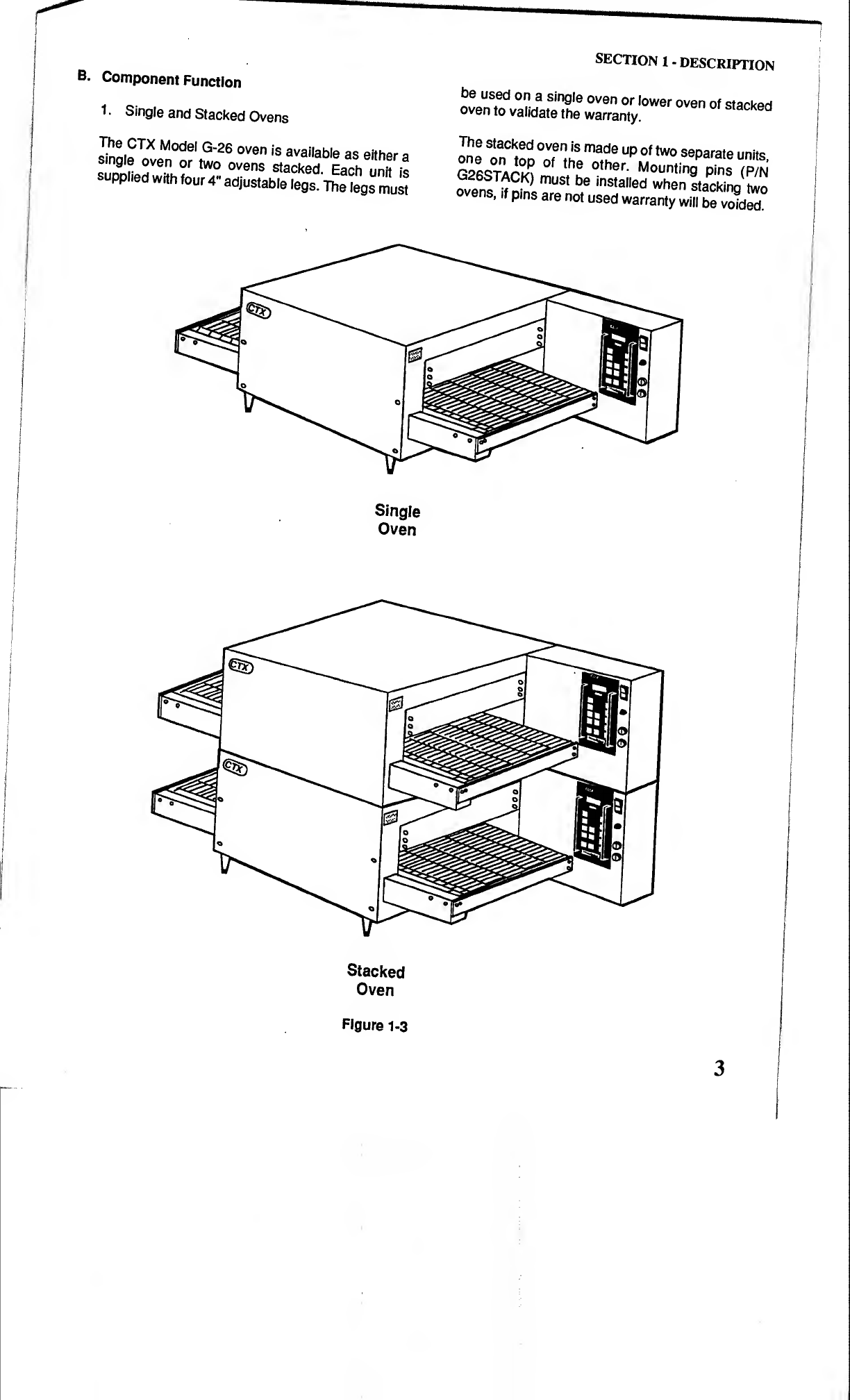
1
•
Single
and
Stacked
Ovens
single^v^or'twcf
ovens
backed^Each
6
'^^
3
supplied
with
four
4"
adjustLrteteg^
The
tegs
must
SECTION
1
-
DESCRIPTION
be
used
on
a
single
oven
or
lower
oven
of
stacked
oven
to
validate
the
warranty.
one
Up
°
f
tw0
ssparate
units,
CPRCTAoJ?
°
f
ot
^
er
-
Mounting
pins
(P/N
ovens
^£T
USt
b
®
inSta,led
when
stacking
two
ens,
if
pms
are
not
used
warranty
will
be
voided.
Single
Oven
Stacked
Oven
Figure
1-3
3
SECTION
1
-
DESCRIPTION
2
.
Cooking
Area
The
CTX
Model
G-26
has
a
26"
(660
mm)
long
cooking
deck
(chamber)
with
a
16"
(406
mm)
wide
conveyor
belt.
3.
Controller
The
Controller
controls
both
the
temperature
and
conveyor
belt
speed
(cook
time)
of
the
oven.
Cook
temperature
can
be
set
from
200°Fto
950°F
(93°C
to
509°C)
and
cook
time
can
be
set
from
01:00
minute
to
30:00
minutes.
4.
Infrared
Heating
Panels
Patented
heating
panels
are
positioned
above
and
below
the
conveyor
belt
of
each
oven
deck
(cham¬
ber).
When
energized
these
panels
emit
infrared
long
waves.
These
waves
do
not
heat
the
air
through
which
they
pass.
Instead
the
waves
are
absorbed
by
the
outer
surface
of
the
product
transported
through
the
oven
on
the
conveyor
belt.
Using
this
application
food
is
placed
on
the
conveyor
and
the
unique
properties
of
the
infrared
waves
cause
it
to
cook
from
the
outside
to
the
center
in
traditional
fashion.
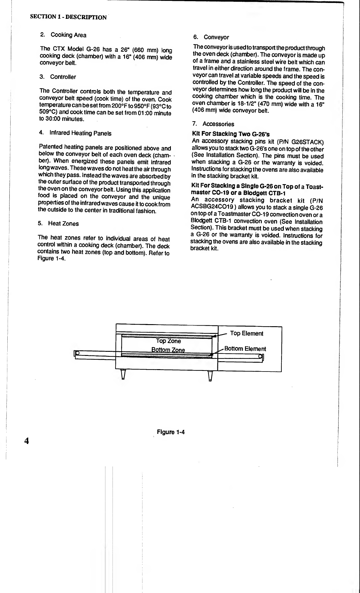
5.
Heat
Zones
The
heat
zones
refer
to
individual
areas
of
heat
control
within
a
cooking
deck
(chamber).
The
deck
contains
two
heat
zones
(top
and
bottom).
Refer
to
Figure
1-4.
6
.
Conveyor
The
conveyor
is
used
to
transport
the
product
through
the
oven
deck
(chamber).
The
conveyor
is
made
up
of
a
frame
and
a
stainless
steel
wire
belt
which
can
travel
in
either
direction
around
the
frame.
The
con¬
veyor
can
travel
at
variable
speeds
and
the
speed
is
controlled
by
the
Controller.
The
speed
of
the
con¬
veyor
determines
how
long
the
product
will
be
in
the
cooking
chamber
which
is
the
cooking
time.
The
oven
chamber
is
18-1/2"
(470
mm)
wide
with
a
16"
(406
mm)
wide
conveyor
belt.
7.
Accessories
Kit
For
Stacking
Two
G-26's
An
accessory
stacking
pins
kit
(P/N
G26STACK)
allows
you
to
stack
two
G-26’s
one
on
top
of
the
other
(See
Installation
Section).
The
pins
must
be
used
when
stacking
a
G-26
or
the
warranty
is
voided.
Instructions
for
stacking
the
ovens
are
also
available
in
the
stacking
bracket
kit.
Kit
For
Stacking
a
Single
G-26
on
Top
of
a
Toast¬
master
CO-19
or
a
Blodgett
CTB-i
An
accessory
stacking
bracket
kit
(P/N
ACSBG24C019)
allows
you
to
stack
a
single
G-26
on
top
of
a
Toastmaster
CO-19
convection
oven
or
a
Blodgett
CTB-1
convection
oven
(See
Installation
Section).
This
bracket
must
be
used
when
stacking
a
G-26
or
the
warranty
is
voided.
Instructions
for
stacking
the
ovens
are
also
available
in
the
stacking
bracket
kit.
Figure
1-4
SECTION
1
-
DESCRIPTION
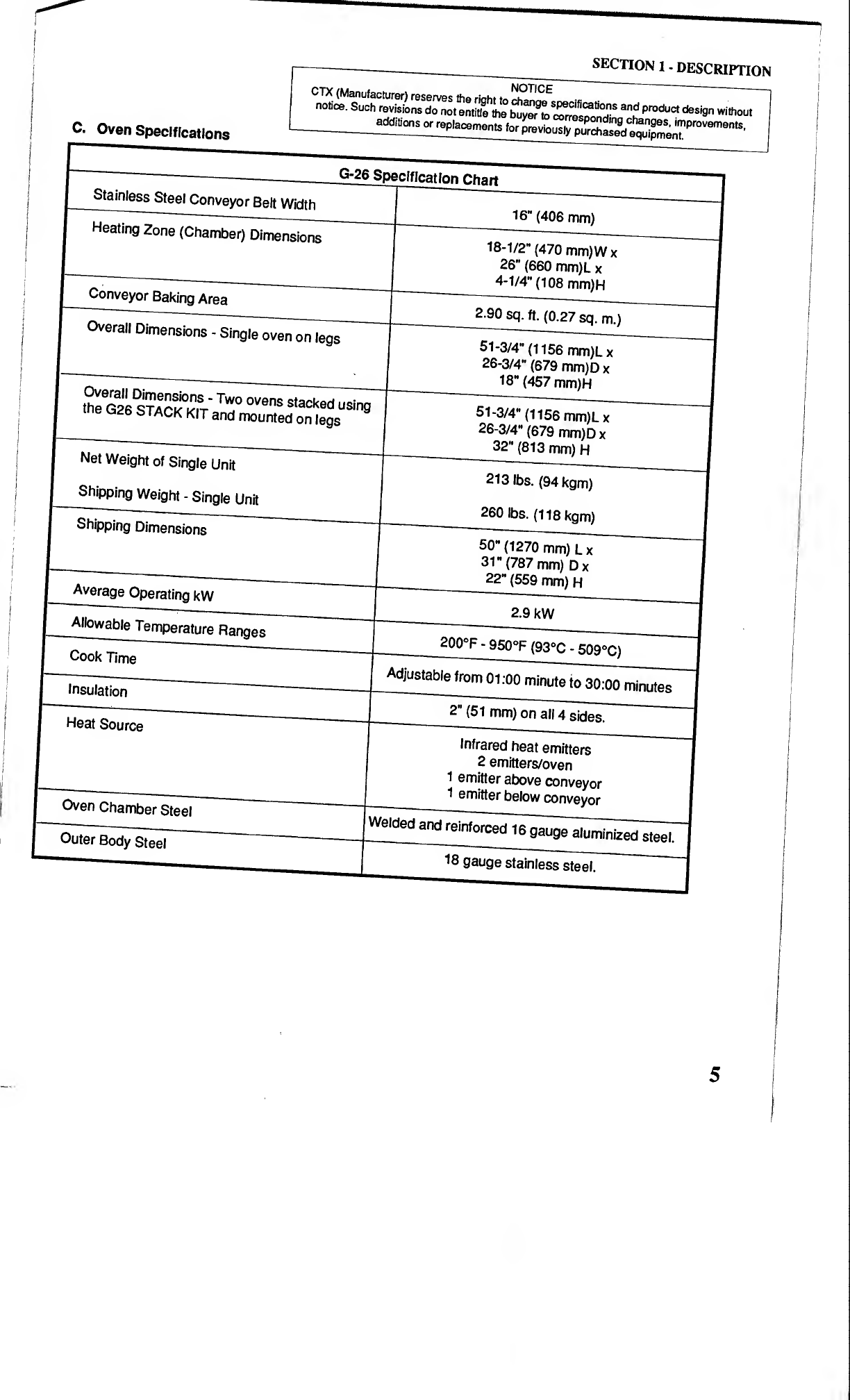
C.
Oven
Specifications
Such
revisions do
not
entitle
the
buyer
to
c^res^nrf"'
S
^
product
desi
9
n
without
additions
or
replacements
for
previously
purged
^
improveme
"‘
s
-
equipment.
Stainless
Steel
Conveyor
Belt
Width
G-26
Specif
ication
Chart
i
-—-
Heating
Zone
(Chamber)
Dimensions
16"
(406
mm)
Conveyor
Baking
Area
Overall
Dimensions
-
Single
oven
on
legs
Overall
Dimensions
-
Two
ovens
the
qTAnv
Lsi-r
uvens
stacked
using
me
C
26
STACK
KIT
and
mounted
on
legs
Net
Weight
of
Single
Unit
Shipping
Weight
-
Single
Unit
Shipping
Dimensions
18-1/2"
(470
mm)Wx
26"
(660
mm)L
x
4-1/4"
(108
mm)H
2.90
sq.
ft.
(0.27
sq.
m.)
51-3/4"
(i
156
mm)Lx
26-3/4"
(679
mm)D
x
18"
(457
mm)H
51-3/4"
(1156
mm)Lx
26-3/4"
(679
mm)Dx
32"
(813
mm)
H
213
lbs.
(94
kgm)
260
lbs.
(118
kgm)
Average
Operating
kW
Allowable
Temperature
Ranges
50"
(1270
mm)
Lx
31"
(787
mm)
Dx
22"
(559
mm)
H
2.9
kW
Cook
Time
200°F
-
950°F
(93°C
-
509°C)
Insulation
Adjustable
from
01:00
minute
to
30:00
minutes
Heat
Source
2
”
(51
mm)
on
all
4
sides.
Oven
Chamber
Steel
Infrared
heat
emitters
2
emitters/oven
1
emitter
above
conveyor
1
smitter
below
conveyor
Outer
Body
Steel
Welded
18
gauge
stainless
steel.
SECTION
1
-
DESCRIPTION
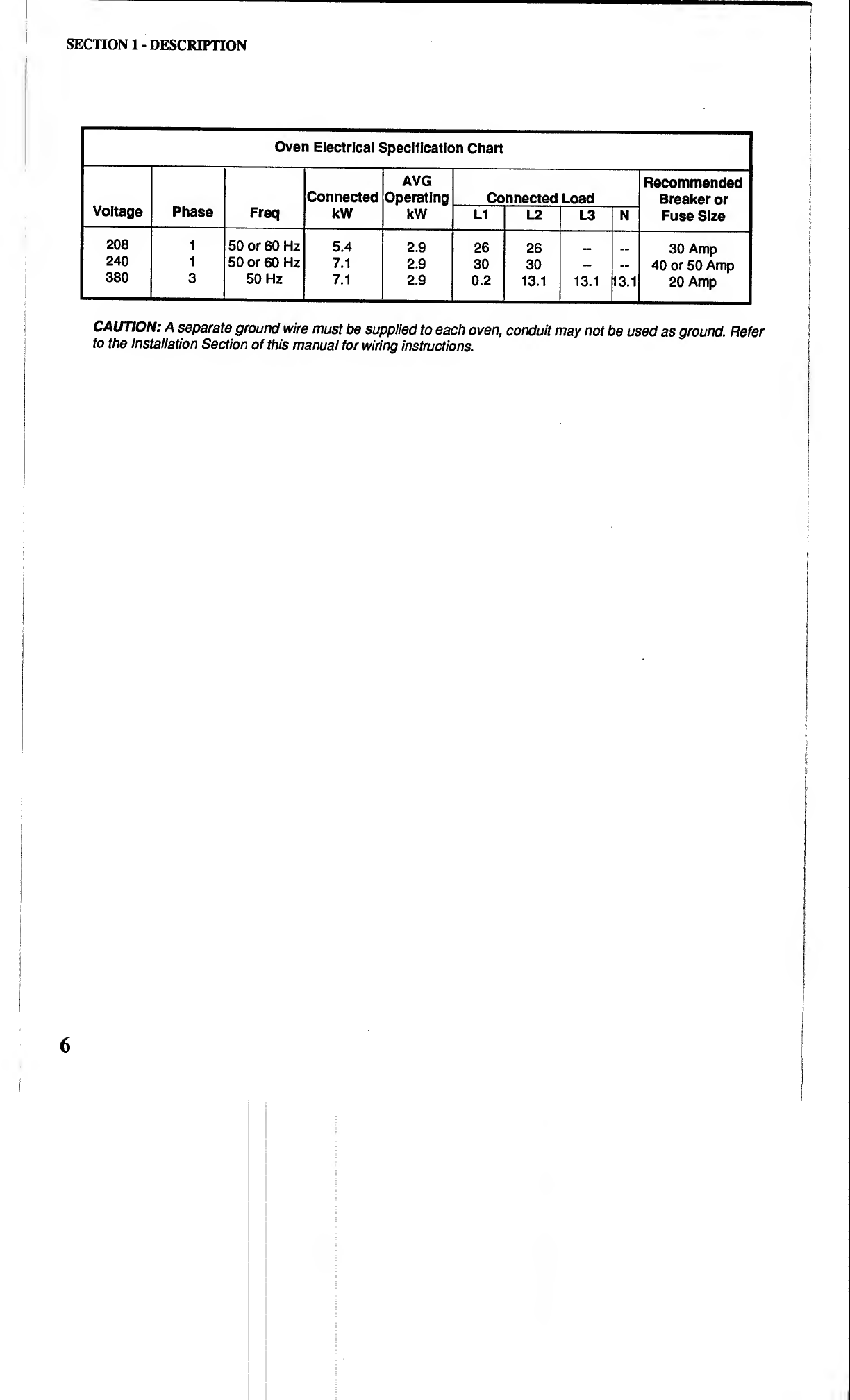
Oven
Electrical
Specification
Chart
Voltage
Phase
Freq
Connected
kW
AVG
Operating
kW
Connected
Load
Recommended
Breaker
or
Fuse
Size
LI
L2
L3
N
208
1
50
or
60
Hz
5.4
2.9
26
26
_
30
Amp
240
1
50
or
60
Hz
7.1
2.9
30
30
—
m
40
or
50
Amp
380
3
50
Hz
7.1
2.9
0.2
13.1
13.1
m
20
Amp
CAUTION:
A
separate
ground
wire
must
be
supplied
to
each
oven,
conduit
may
not
be
used
as
ground.
Refer
to
the
Installation
Section
of
this
manual
for
wiring
instructions.
6

SECTION
1
-
DESCRIPTION
Oven
Dimension
Drawings
51-3/4"
1315mm
26-3/4"
—679mm-
16-1/2“
_
'470mm
Single
Oven
on
Legs

SECTION
2
INSTALLATION
A.
Inspect
for
Shipping
Damage
All
shipping
containers
should
be
examined
for
dam¬
age
before
and
during
unloading.
This
equipment
was
carefully
inspected
and
packaged
at
the
factory.
The
freight
carrier
has
assumed
responsibility
for
its
safe
transit
and
delivery.
If
equipment
is
received
in
damaged
condition,
either
apparent
or
concealed,
a
claim
must
be
made
with
the
delivering
carrier.
1.
Apparent
Damage
or
Loss
-
If
damage
or
loss
is
apparent
it
must
be
noted
on
the
freight
bill
or
express
receipt
at
the
time
of
delivery,
and
it
must
be
signed
by
the
carrier’s
agent
(driver).
If
this
is
not
done,
the
carrier
may
refuse
the
claim.
The
carrier
will
supply
the
necessary
claim
forms.
2
.
Concealed
Damage
or
Loss
-
If
damage
or
loss
is
NOT
apparent
until
after
equipment
is
uncrated,
a
request
for
inspection
of
concealed
damage
must
be
made
with
carrier
within
15
days.
The
carrier
will
make
an
inspection
and
will
supply
necessary
claim
forms.
Be
certain
to
retain
all
contents
plus
external
and
internal
packaging/crating
materials
for
inspec¬
tion.
B.
Placement
of
Oven
Some
very
important
considerations
must
be
made
when
choosing
the
place
where
the
oven
is
to
oper¬
ate.
1.
This
oven
is
conveyorized
and
operates
continu¬
ously.
It
should
be
placed
so
it
fits
into
the
“flow”
of
the
operation.
2
.
Drafts
entering
the
oven
chambers
can
cause
inconsistent
cooking
results.
Check
the
area
sur¬
rounding
the
oven
and
eliminate
sources
of
drafts
such
as
open
windows
or
doors
and
fans
or
other
appliances
that
cause
air
circulation.
3.
Oven
should
be
positioned
so
hot
air
from
an¬
other
piece
of
equipment
cannot
enter
oven
cooling
fan
air
intake
on
the
control
compartment.
Serious
problems
could
occur.
NOTE:
To
validate
a
new
oven(s)
warranty
a
factory
certified
installer
must
verify
that
Steps
C
thru
K
have
been
performed
correctly.
9
SECTION
2
-
INSTALLATION
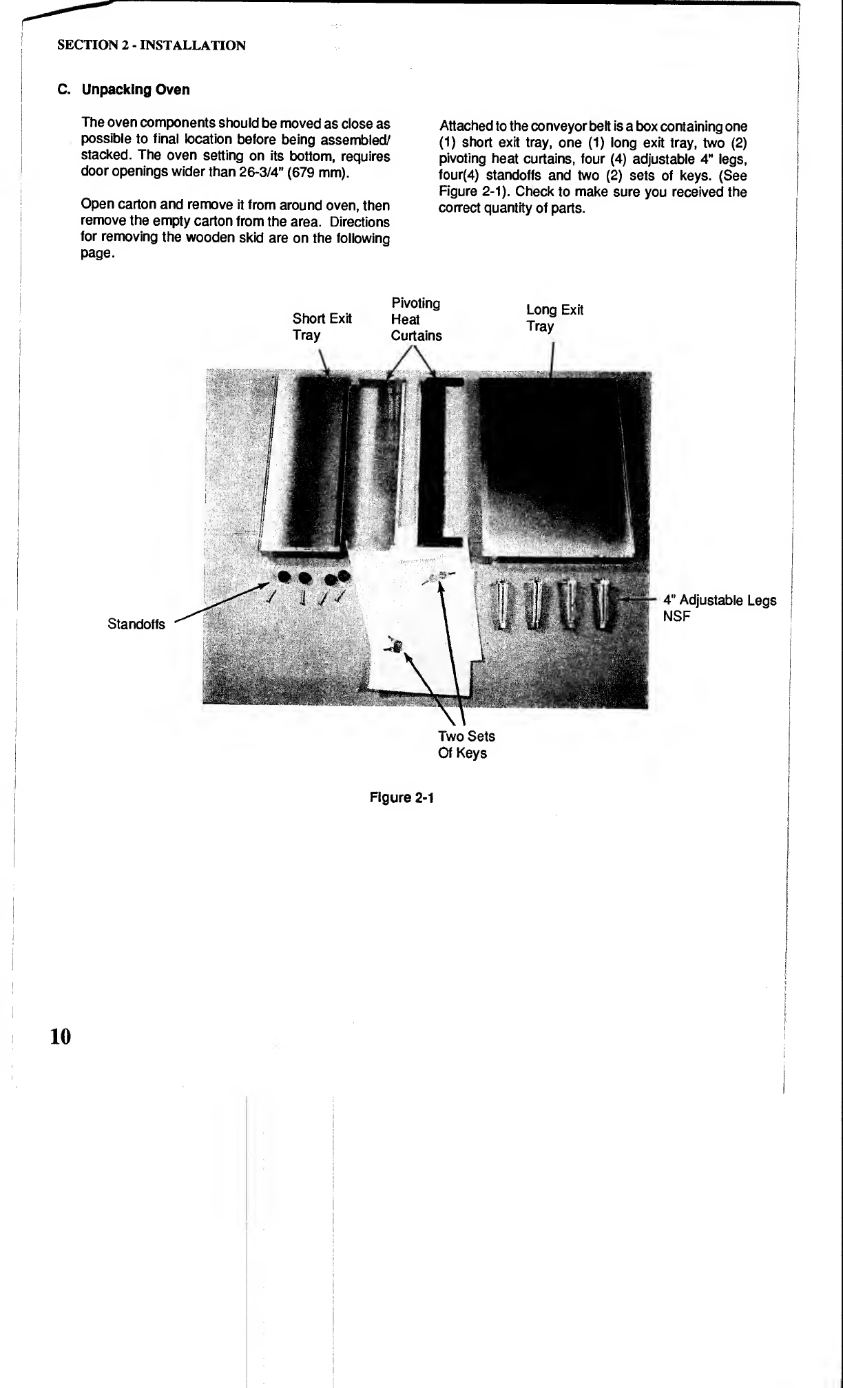
C.
Unpacking
Oven
The
oven
components
should
be
moved
as
close
as
possible
to
final
location
before
being
assembled/
stacked.
The
oven
setting
on
its
bottom,
requires
door
openings
wider
than
26-3/4"
(679
mm).
Open
carton
and
remove
it
from
around
oven,
then
remove
the
empty
carton
from
the
area.
Directions
for
removing
the
wooden
skid
are
on
the
following
page.
Attached
to
the
conveyor
belt
is
a
box
containing
one
(1)
short
exit
tray,
one
(1)
long
exit
tray,
two
(2)
pivoting
heat
curtains,
four
(4)
adjustable
4"
legs,
four(4)
standoffs
and
two
(2)
sets
of
keys.
(See
Figure
2-1).
Check
to
make
sure
you
received
the
correct
quantity
of
parts.
Standoffs
Pivoting
Short
Exit
Heat
Tray
Curtains
Long
Exit
Tray
4"
Adjustable
Legs
NSF
Two
Sets
Of
Keys
Figure
2-1
10
SECTION
2
-
INSTALLATION
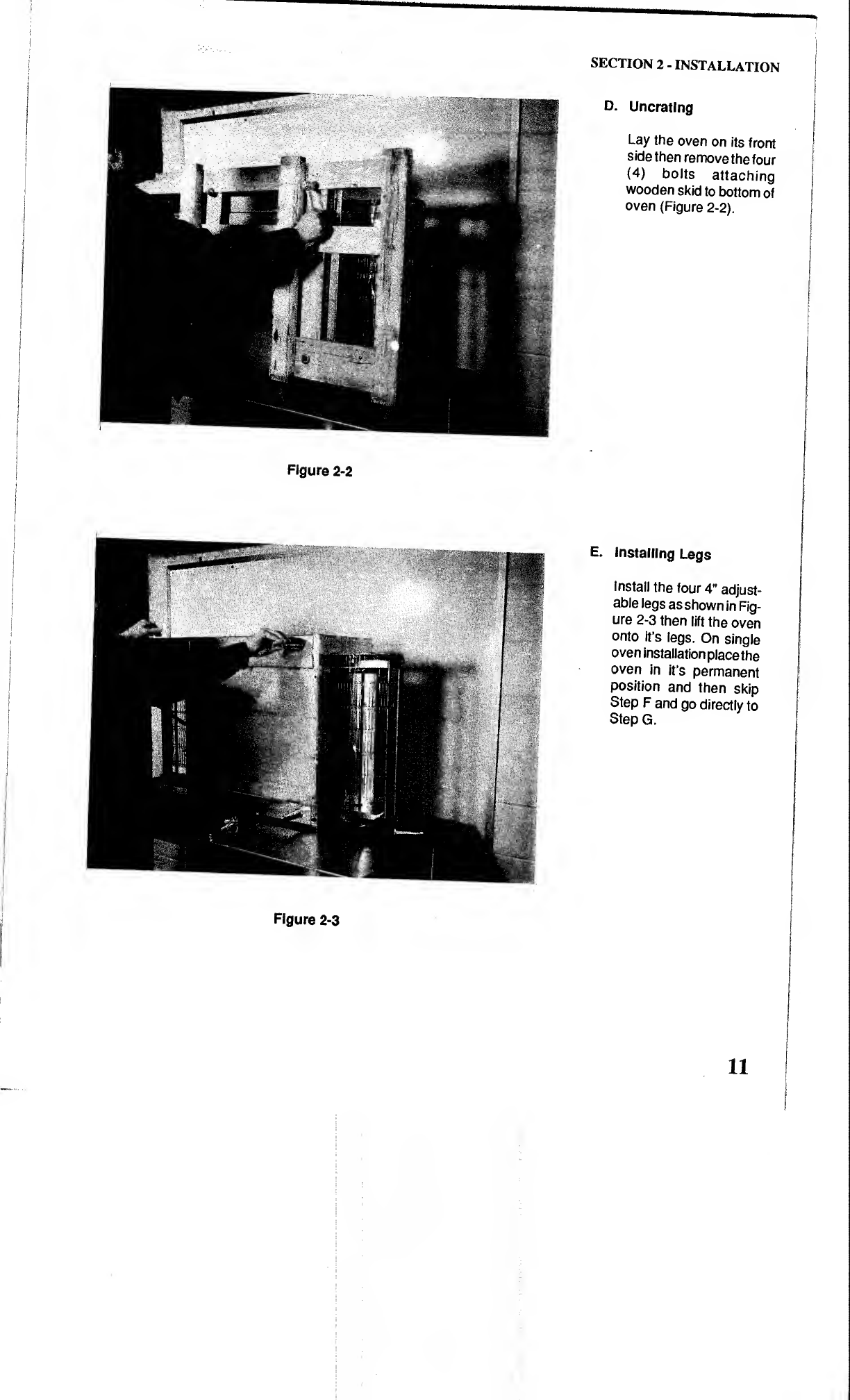
D.
Uncrating
Lay
the
oven
on
its
front
side
then
remove
the
four
(4)
bolts
attaching
wooden
skid
to
bottom
of
oven
(Figure
2-2).
Figure
2-2
E.
installing
Legs
Install
the
four
4"
adjust¬
able
legs
as
shown
in
Fig¬
ure
2-3
then
lift
the
oven
onto
it’s
legs.
On
single
oven
installation
place
the
oven
in
it’s
permanent
position
and
then
skip
Step
F
and
go
directly
to
Step
G.
Figure
2-3
11
SECTION
2
-
INSTALLATION
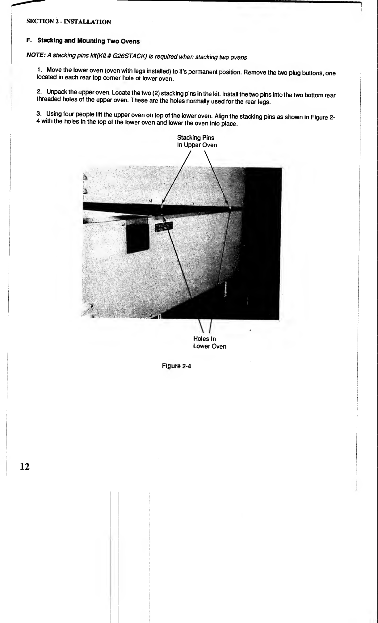
F.
Stacking
and
Mounting
Two
Ovens
NOTE:
A
stacking
pins
kit(Kit
#
G26STACK)
is
required
when
stacking
two
ovens
1.
Move
the
lower
oven
(oven
with
legs
installed)
to
it’s
permanent
position.
Remove
the
two
plug
buttons,
one
located
in
each
rear
top
corner
hole
of
lower
oven.
?•
u
"
pack
the
u
PPe
r
oven.
Locate
the
two
(2)
stacking
pins
in
the
kit.
Install
the
two
pins
into
the
two
bottom
rear
threaded
holes
of
the
upper
oven.
These
are
the
holes
normally
used
for
the
rear
legs.
3.
Using
four
people
lift
the
upper
oven
on
top
of
the
lower
oven.
Align
the
stacking
pins
as
shown
in
Figure
2-
4
with
the
holes
in
the
top
of
the
lower
oven
and
lower
the
oven
into
place.
Stacking
Pins
In
Upper
Oven
Holes
In
Lower
Oven
Figure
2-4

SECTION
2
-
INSTALLATION
)
j
i
4.
Once
the
ovens
are
stacked
and
secured
check
to
make
sure
the
oven(s)
are
level.
Adjust
the
legs
if
necessary
as
shown
in
Figure
2-5.
Figure
2-5
G.
Stacking
a
single
G-26
oven
over
a
Toastmas¬
ter
CO-19
convection
oven
ora
Blodgett
CTB-
1
convection
oven.
NOTE:
A
stacking
bracket
kit
(P/N
ACSBG24C019)
must
be
used
for
this
in¬
stallation
or
warranty
is
voided.
1-
Lay
the
G-26
on
its
front
side.
Then
using
the
four
bolts
supplied
in
the
kit,
secure
bracket
to
bot¬
tom
of
oven
using
the
threaded
holes
normally
used
for
legs.
Opening
in
sidewall
must
be
at
rear
of
oven
as
shown
in
Fiq-
ure
2-6.
Figure
2-6
13

SECTION
2
-
INSTALLATION
2
.
Using
four
people
lift
the
G-26
and
place
it
on
topof
the
convection
oven
as
shown
in
Figure
2-7.
Figure
2-7
H.
Conveyor
Belt
and
Temperature
Display
The
conveyor
belt
is
designed
to
travel
in
either
direction
using
the
conveyor
Reversing
Key
Switch.
The
temperature
display
may
be
set
for
either
°F
or
°C.
Your
Certified
Installer
will
set
both
of
these
functions
for
you
during
the
installation.
If
you
require
a
change
in
the
degrees
display
(Fahrenheit
or
Centigrade)
in
the
future
call
your
local
Autho¬
rized
Service
Agency.
Figure
2-8
J.
Electrical
Connection
SECTION
2
-
INSTALLATION
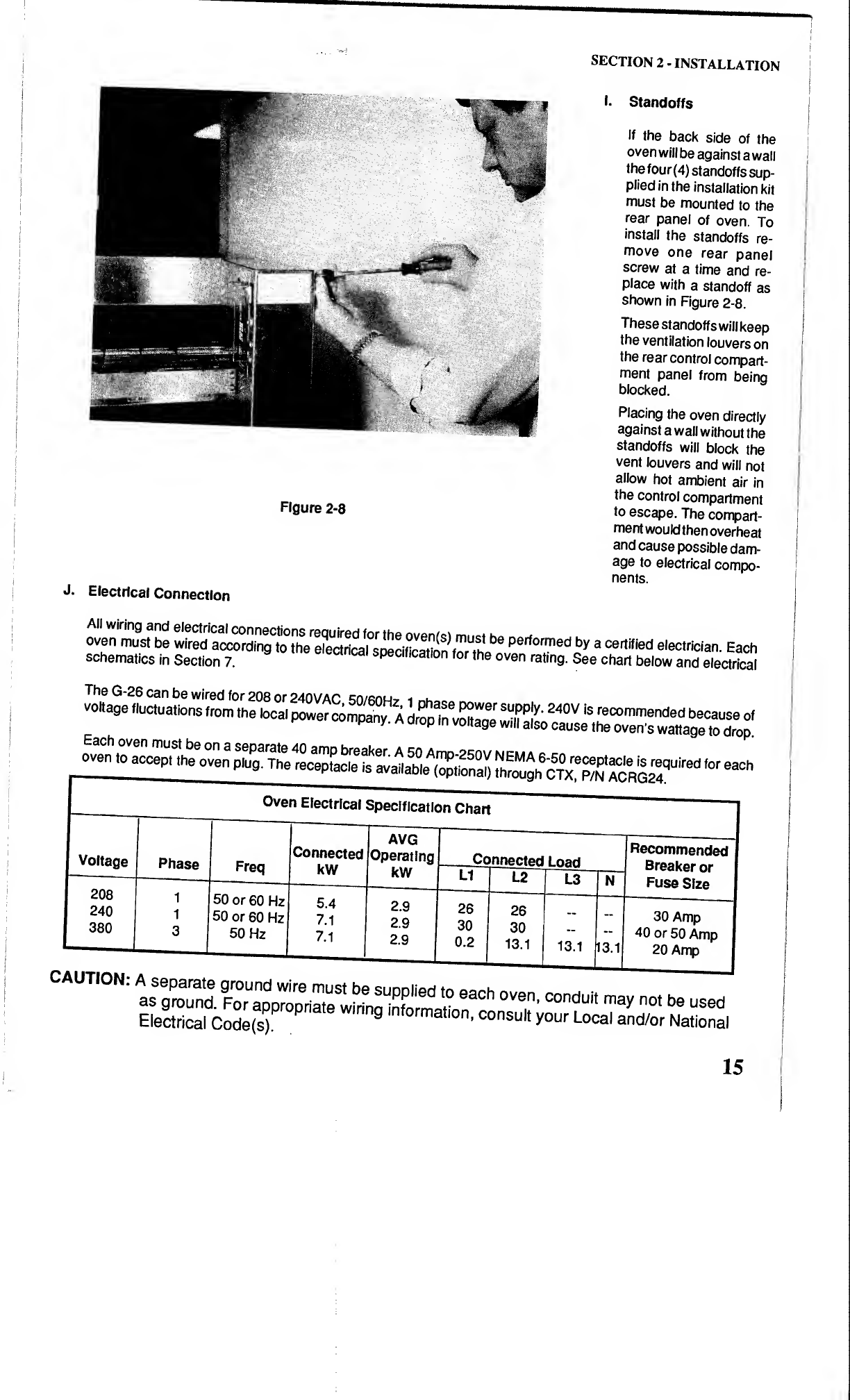
I-
Standoffs
If
the
back
side
of
the
oven
will
be
against
a
wall
the
four
(4)
standoffs
sup¬
plied
in
the
installation
kit
must
be
mounted
to
the
rear
panel
of
oven.
To
install
the
standoffs
re¬
move
one
rear
panel
screw
at
a
time
and
re¬
place
with
a
standoff
as
shown
in
Figure
2-8.
These
standoffs
will
keep
the
ventilation
louvers
on
the
rear
control
compart¬
ment
panel
from
being
blocked.
Placing
the
oven
directly
against
a
wall
without
the
standoffs
will
block
the
vent
louvers
and
will
not
allow
hot
ambient
air
in
the
control
compartment
to
escape.
The
compart¬
ment
would
then
overheat
and
cause
possible
dam¬
age
to
electrical
compo¬
nents.
vo«ageS^
Oven
Electrical
Specification
Chart
Voltage
208
240
380
Phase
1
1
3
50
or
60
Hz
50
or
60
Hz
50
Hz
Connected
kW
5.4
7.1
7.1
AVG
Operating
I
kW
2.9
2.9
2.9
Connected
l
oad
26
30
0.2
26
30
13.1
13.1
N3.1
I
Recommended
Breaker
or
Fuse
Size
30
Amp
40
or
50
Amp
20
Amp
CAUTION;
A
=
9~e
,
™
-
Pleach
oven,
condui,
may
no,
be
used
Electrical
Code(s).
’
consu
*
y°
ur
Local
and/or
National
15
SECTION
2
-
INSTALLATION
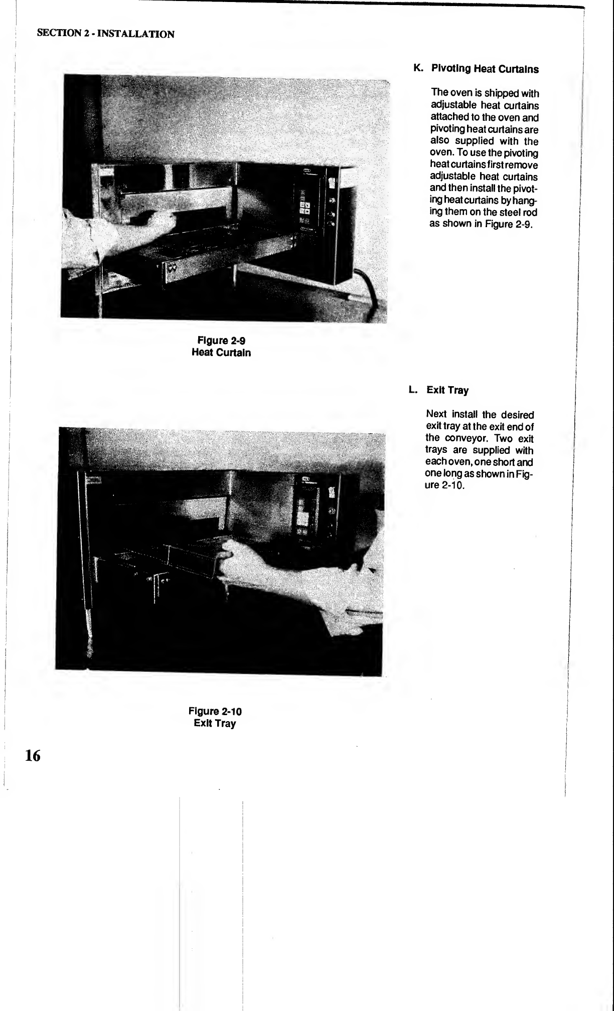
K.
Pivoting
Heat
Curtains
The
oven
is
shipped
with
adjustable
heat
curtains
attached
to
the
oven
and
pivoting
heat
curtains
are
also
supplied
with
the
oven.
To
use
the
pivoting
heat
curtains
first
remove
adjustable
heat
curtains
and
then
install
the
pivot¬
ing
heat
curtains
by
hang¬
ing
them
on
the
steel
rod
as
shown
in
Figure
2-9.
Figure
2*9
Heat
Curtain
L.
Exit
Tray
Next
install
the
desired
exit
tray
at
the
exit
end
of
the
conveyor.
Two
exit
trays
are
supplied
with
each
oven,
one
short
and
one
long
as
shown
in
Fig¬
ure
2-10.
16
Figure
2-10
Exit
Tray
Table of contents
Other Middleby Oven manuals


