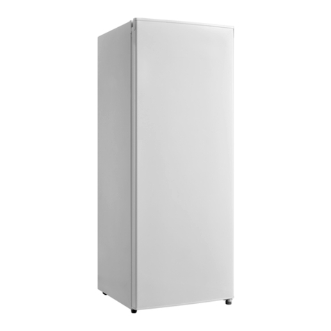
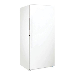
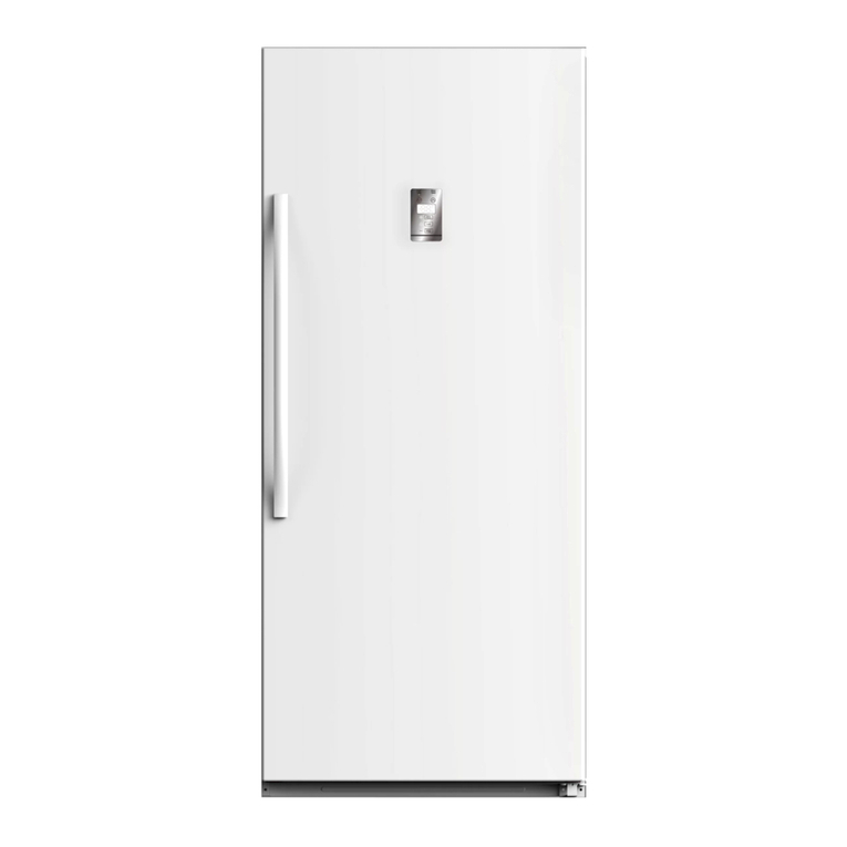
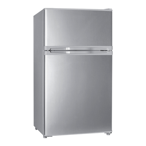
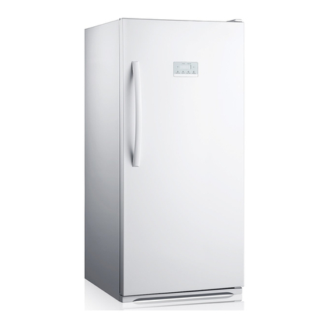
Midea HS-338FWEN-W User manual

MODEL:HS-338FWEN-W
Instruction Manual
Upright Freezer


Important Safety Notice
The Maintenance Manual is only for the use of maintenance personnel with certain experience and
background in electrical, electronic and mechanical field.
Any attempt to repair main devices may lead to personal injury and property loss.
Manufacturers or distributors are not responsible for the content of the Manual and interpretation
thereof.
Midea Refrigerators
Technical Maintenance Manual
Copyright @2016
All rights reserved. Replication of all or part of the Manual in any forms shall not be allowed without
written approval by the Overseas Sales Corporation of Midea Refrigerators.

Contents
1.SAFETY WARNING CODE .........................................................................................................1
1.1WARNING FOR OPERATION SAFETY...................................................................................................1
1.2SAFETY INSTRUCTION FOR REFRIGERANT.........................................................................................4
2.DESCRIPTION FOR PRODUCT FEATURES............................................................................ 5
3.INSTALLATION AND COMMISSIONING ................................................................................ 6
3.1HANDLING .......................................................................................................................................6
3.2DISASSEMBLY (NONE)......................................................................................................................6
3.3 INSTALLATION LOCATION ................................................................................................................6
3.4 LEVELING OF THE REFRIGERATOR....................................................................................................6
3.5CHANGE THE DOOR OPENING DIRECTION..........................................................................................7
3.6 INSTALLATION OF HANDLE ..............................................................................................................9
3.7 INSTALLATION OF DOOR LOCK(NONE)...................................................................................... 10
3.8ADJUSTMENT TO LEVEL THE DOOR(NONE)............................................................................... 10
3.9ADJUSTMENT TO SHELVES(NONE)............................................................................................10
4.TERMS........................................................................................................................................ 10
4.1 DEFINITION OF MODEL(NONE)......................................................................................................10
4.2LOCATION OF NAMEPLATE..............................................................................................................10
5.PRODUCT SPECIFICATION.................................................................................................... 11
5.1 TYPESPECIFICATION(NONE)........................................................................................................... 11
5.2 ELECTRICAL PARAMETERS.............................................................................................................11
5.3REFRIGERATING TEMPERATURE......................................................................................................11
5.4DEFROSTING PARTS ........................................................................................................................12
5.5CIRCUIT DIAGRAM..........................................................................................................................12
6.INTERNAL VIEWAND DIMENSION ...................................................................................... 13
6.1MAIN PARTS AND THEIR NAMES......................................................................................................13
6.2EXTERNAL DIMENSION...................................................................................................................13
7.REFRIGERATING PIPING SYSTEM AND CIRCULATING ROUTE OF COOLING AIR7.1 REFRIGERATING
PIPING SYSTEM....................................................................................................................................15
7.2CIRCULATING ROUTE OF COOLING AIR............................................................................................16
8. DISMANTLING OF PARTS...................................................................................................... 17
8.1 PARTS ON THE DOOR......................................................................................................................17
8.2PARTS INSIDE THE REFRIGERATOR .................................................................................................. 17
8.3 LIGHT SYSTEM...............................................................................................................................18
8.4AIR DUCTAND FAN MOTOR.............................................................................................................18
8.5EVAPORATOR AND TEMPERATURE SENSING SYSTEM .......................................................................19
8.6COMPRESSOR CASE ........................................................................................................................20

8.7DISPLAY AND MAIN CONTROLPANEL..............................................................................................21
8.8 BAR COUNTER(NONE)................................................................................................................... 22
8.9 WATER DISPENSER(NONE).............................................................................................................22
8.10 ICE MAKER(NONE)......................................................................................................................22
9. FUNCTION AND OPERATION9.1 OPERATION PANEL...........................................................................23
9.2 BUTTON.........................................................................................................................................23
9.3 DISPLAY SCREEN ...........................................................................................................................24
9.4 DISPLAY ........................................................................................................................................24
IF NO FAILURE OCCURS,THE CURRENT OPERATION GEAR WILLBE DISPLAYED.9.5 SETTING OF THE GEAR
............................................................................................................................................................24
9.6 SUPER FREEZE............................................................................................................................... 24
9.7 FAULT CODE AND SOLUTIONS ........................................................................................................24
9.8DEFROSTING FUNCTION .................................................................................................................25
9.9TEST MODE.....................................................................................................................................25
9.10SELF-DIAGNOSIS ..........................................................................................................................26
10.CIRCUIT DESCRIPTION10.1 POWER SUPPLY ....................................................................................27
10.2DOOR TRIP TEST CIRCUIT.............................................................................................................. 27
10.3TEMPERATURE TEST CIRCUIT........................................................................................................27
10.4FAN MOTOR CIRCUIT OF THE FREEZING CHAMBER ........................................................................28
10.5REFRIGERATOR FAN MOTOR CIRCUIT (NONE)...............................................................................29
10.6CONDENSING FAN MOTOR CIRCUIT (NONE)..................................................................................29
10.7DAMPER MOTOR CIRCUIT (NONE)................................................................................................29
10.8RESISTANCE VALUE OF THE SENSOR (R/T)....................................................................................29
11.TROUBLESHOOTING METHOD........................................................................................... 30
11.1 NO REFRIGERATION .....................................................................................................................30
11.2 COMPRESSOR FAILURE.................................................................................................................31
11.3 DEFROSTING IS NOT WORKING.....................................................................................................31
11.4 FAN IN THE FREEZING CHAMBER IS ABNORMAL ...........................................................................32
11.5 DAMPER IS ABNORMAL(NONE)....................................................................................................32
11.6 LIGHTS INSIDE THE REFRIGERATOR DON’T LIGHT UP....................................................................32
12. FIGURES AND DETAILS OF REPAIR PARTS(DOCUMENTSARE PROVIDED
SEPARATELY)............................................................................................................................... 33
12.1 FIGURE........................................................................................................................................33
12.2 LIST OF PARTS AND COMPONENTS................................................................................................33
13APPENDIX:......................................................................................................................................33
13.1ELECTRICAL SCHEMATIC DIAGRAM .............................................................................................33
13.2REFRIGERATOR MAINTENANCE TOOLING AND EQUIPMENT AND MATERIAL..................................33

1
1.Safety Warning Code
1.1Warning for operation safety

2

3

4
1.2Safety instruction for refrigerant

5
2.Description for product features
This product is provided with following features:
(The picture is only for reference, and specific appearance and configuration are subject to the real
product)
1) Full air-cooling and frost-free design
2) Display control board is located on the door
3) Magnetically control switch
4) Electronic temperature control system with more accurate temperature control.

6
3.Installation and commissioning
3.1Handling
1) Protecttherefrigeratorinmovingit
Sameasshownasleftphoto,pleasemoveitbyhandcartwi
thcushion
2) Removeallpackingmaterialsandbottomcushion,then
moveintohouseforplacement
3) Aftermovingittoappropriatelocation,waitfor2hoursbe
forepoweron.
3.2Disassembly (None)
The refrigerator door needs to be dismantled if it cannot enter the room in the whole.
3.3 Installation location
Location that is easy for ventilation shall be
chosen to facilitate heat dissipation, enhance
its performance and reduce the energy
consumption.
3.4 Leveling of the refrigerator
If the refrigerator cannot be placed steadily,
adjust the footing to level it.

7
3.5Change the door opening direction
1、Remove the hinge cover and plates from the
top of refrigerator
2、Pull out the fast connector of door signal
wire, remove the upper hinge screw, then
remove the upper hinge
3、Pull out the door ,remove the bottom hinge

8
4、
Reversal the bottom hinge, Unscrew the hinge
pin from the bottom hinge and move it to the
other side(a), then secure the bottom hinge to the
bottom left side of the refrigerator
5、Remove the door block from the bottom, right
side of the door and attach it to the other side.
6、
Install the door and the signal to other side,
connect the terminal and install upper hinge(a),
lid the upper hinge cover and the door end cap

9
3.6 Installation of handle
Note: Figures in the user manual are only for reference. The actual product may differ slightly.
The refrigerator must be disconnected from the source of electrical supply before attempting the
installation of accessory.
Schematic diagram of handle installation
Design sketch of installed handle
①
1)Remove the insert pin ①
①
2)Adjust the handle ③to the installing hole
and tighten screw ②.
②③
3Cover the nut cap ④of handle hole
④
(Pictures and objects are not consistent, in order to prevail in kind)

10
3.7 Installation of door lock(None)
3.8 Adjustment to level the door(None)
3.9 Adjustment to shelves(None)
4.Terms
4.1 Definition of model(None)
4.2Location of nameplate
(The picture is only for reference, and specific appearance and configuration are subject to the real
product)
Label

11
5.Product specification
5.1 typespecification(None)
5.2 Electrical parameters
Product Name
CE-BD260WE-ST
Product Code
22031010001022
Name
Item
Type
Specification
Compressor
Compressor
/
PZ80E1A
Starter
PTC
8EA19C3/QP2-15
Overload protector
OLP
4TM117NFBYY/DRB12N61A1
Winding resistance of
compressor wiring terminal
Rmc:10~20Ω
Rsc:30~50Ω
Rms=Rmc+Rsc
Motor
Fan motor of the freezing
chamber
DC12V/≤3W
Ventilation door of the
refrigerating chamber
/
/
Condensation fan
/
/
Lights inside the
refrigerator
Lights inside the freezing
chamber
/
/
Lights inside the refrigerating
chamber
/
/
Switch of the refrigerator door
DC12V
5.3Refrigerating temperature
Temperature tolerance ≤ 2°C
Compartment
The highest (°C)
Lowest (°C)
Freezing
-14
-24

12
Refrigerating
/
/
Variable temperature
/
/
5.4Defrosting parts
Defrosting period
Initial defrosting period
Normal defrosting period
Temperature is lower than 0°C
6~24 hours
Defrosting sensor
NTC
B3839
Thermal fuse
73/77℃
Defrosting heater in freezing chamber
230V/245W
5.5Circuit diagram

13
6.Internal view and dimension
6.1Main parts and their names
1 top beam
2.Air duct components in freezing chamber
3. Flipping cover
4.Glass shelve
5. F upper drawer assembly
6. F middle drawer assembly
7. F bottom drawer assembly
8.Bottle frame in freezing chamber
9. Door handle of fridge compartment
6.2External dimension
Front view
Side view

14
Down view
Open Door
Maximum open angle of door(135°)
(The picture is only for reference, and specific appearance and configuration are subject to the real
product)

15
7.Refrigerating piping system and circulating route of cooling air7.1
Refrigerating piping system
Compressor →Condenser →Anti-condensation tube →Dry filter → Capillary tube
→ Evaporator → Regenerator → Suction tube → Compressor
(The picture is only for reference, and specific appearance and configuration are subject to the real
product)
Table of contents
Other Midea Freezer manuals

Midea
Midea UR-BD295-DQ User manual

Midea
Midea JHSD172 User manual

Midea
Midea WHS-384C1 User manual

Midea
Midea MU138SWAR1RC1 User manual

Midea
Midea MRU17F6AWW User manual

Midea
Midea SINGLE DOOR Series User manual

Midea
Midea UR-PC160E-DQ User manual

Midea
Midea MCH142W User manual

Midea
Midea UR-BD240WE-ST User manual

Midea
Midea MF411W User manual

Midea
Midea UR-BD199-DQ User manual

Midea
Midea MCH295W User manual

Midea
Midea HS-377CN User manual

Midea
Midea MRU17B2AWW User manual

Midea
Midea COMPACT Series User manual

Midea
Midea MDRC152FE User manual

Midea
Midea HS-131CN User manual

Midea
Midea MRC07M3AWW User manual

Midea
Midea UR-BD143-DQ User manual

Midea
Midea MCH198W User manual