Last update: 2014/01/19 10:10 pedal_box http://www.midibox.org/dokuwiki/doku.php?id=pedal_box
http://www.midibox.org/dokuwiki/ Printed on 2020/10/14 01:02
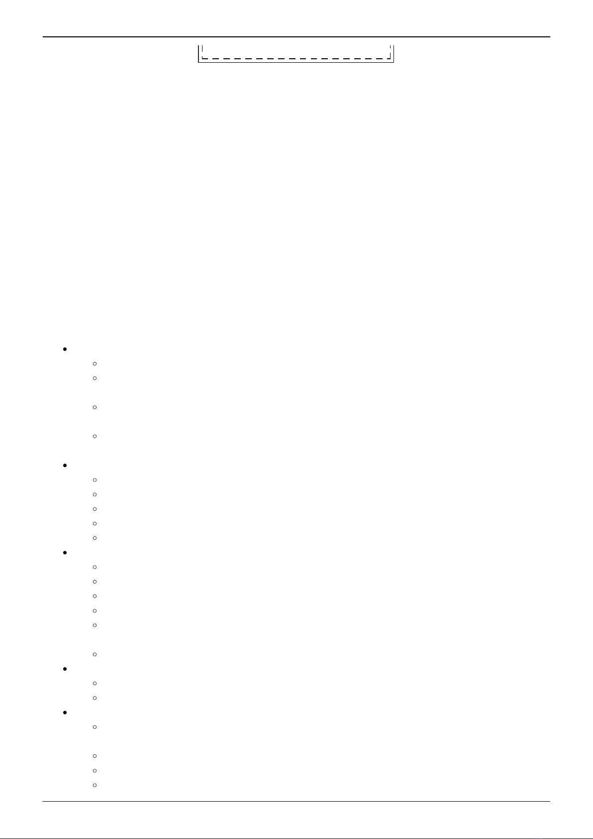
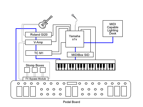
Floorboard.
Is a complete MIOS/MBHP powered floorboard. It can support up to 16 buttons, with banks so there is
up to 128 virtual buttons.
No matter how many buttons you connect, you can always access all 128 virtual buttons
It also supports another 16 fixed buttons, that are the same regardless of bank. Great for boost, or
effect on/off functions. A further 2 special function buttons allow bank up/down and special functions.
Up to 8 relay's can be triggered and of course up to 8 expression pedals.
Each button or pedal can be assigned to a specific device, up to 7 devices can be controlled over 7
midi channels.
Pedal Box / Pedal Board features an extensive display system;
Program changes can be named, controls can be named, and can also display on/off, a meter showing
approximate position for pedals. It can display tap tempo rate, or even the name of a value for a
control - eg. For an Amp model select CC, it can display the model name selected.
Features
Expression Pedals
Up to 8 Expression Pedals or Pedal inputs (CV / 10k pot)
Individual option for pedals to be 'dynamic' by changing the midi messages sent based on
the Rig COntrol Patch Change
Value scaled between pre-defined min and max values (can also be different for each
program change)
A MIDI CC can be configured to act exactly as if it were connected to an analogue in (The
8 limit still applies)
LCD Display
Named Program Changes
Named CC events
Bar Graph displaying value/on/off
up to 10 specific CC value name tables for effect selection, etc
Tap Tempo BPM display
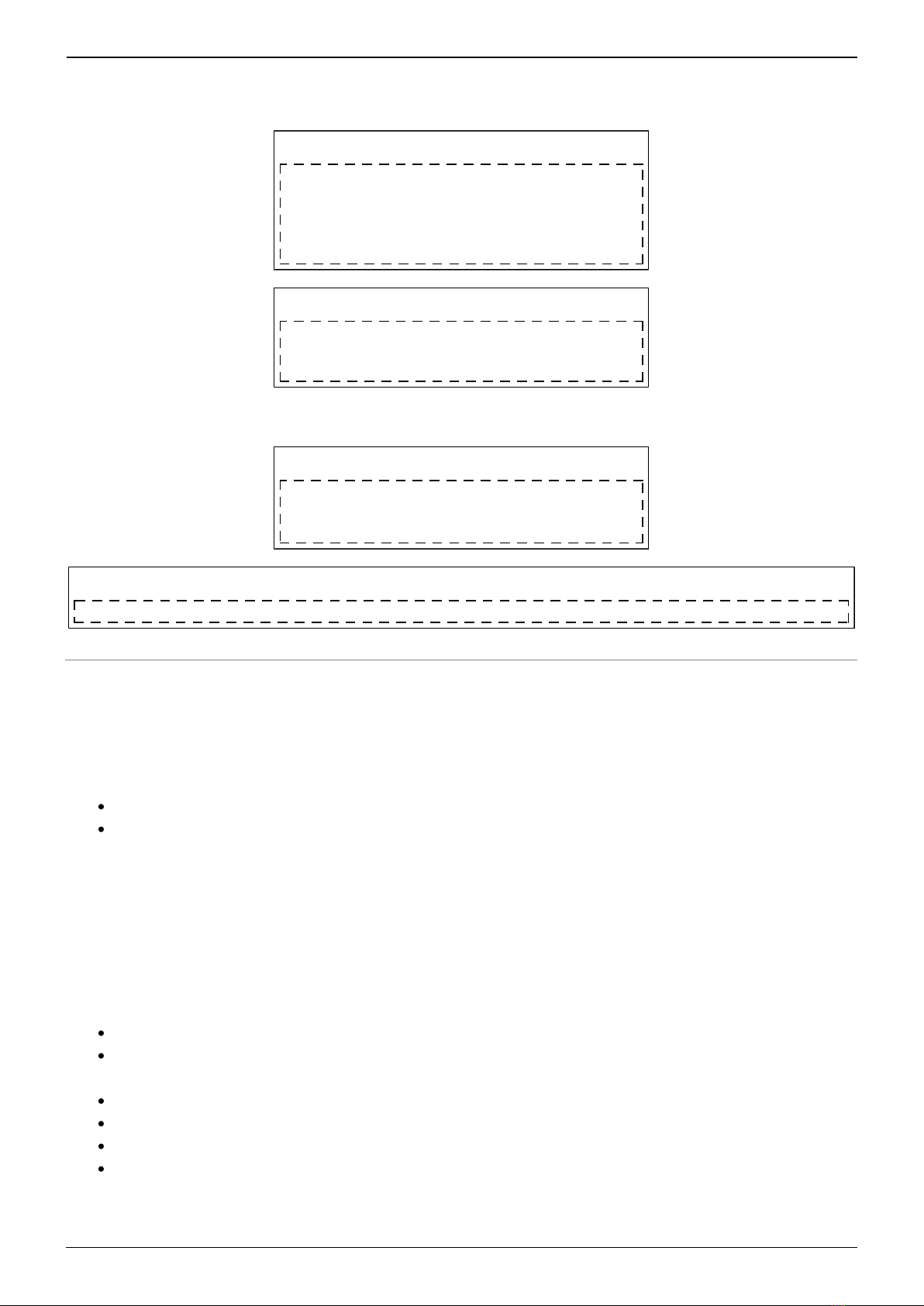
Pedal Board mode (max 34 buttons) - Optional
Up to 16 fixed midi output buttons with LED indicators
Up to 16 banked buttons for up to 128 midi commands with 16 LED indicators
Buttons toggle between a pre-defined min and max value
2 modes for buttons: switching or momentary
Bank displayed on 2×7 segment LED digits or LCD (use 2×20 screen for bank display on
LCD)
Bank Up / Down buttons
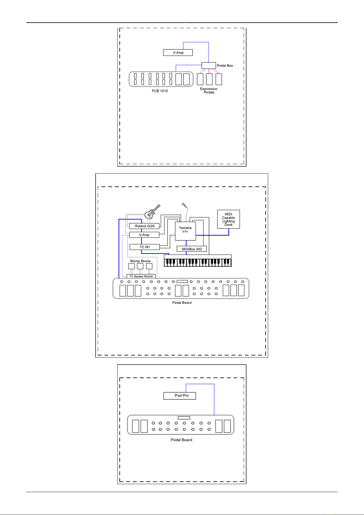
Multiple MIDI Devices
Can be setup to control up to 7 devices (1 bankstick required per device)
Each pedal or button has it's own device assignment
Rig Control
Internal patches allow up to 32 midi events can be sent at the same time giving you
complete control of all you gear
Patches can be triggered by any button (PbD only) or a MIDI IN event (PbX only)
Up to 8 relays can be used to switch amplifier channels, or other analog switch.
Relays can be triggered from patches, a button or a MIDI In event


