aion AZURE User manual

AZURE ANALOG CHORUS 1
PROJECT NAME
AZURE
BASED ON
EFFECT TYPE
PROJECT SUMMARY
DOCUMENT VERSION
BOSS®CE-2 Chorus
One of the most revered chorus pedals of all time, it uses analog BBDs to modulate the signal, resulting
in the warm, rounded tone characteristic of this era.
Analog chorus 1.0.0 (2021-11-26)
BUILD DIFFICULTY
Intermediate
Actual size is 2.3” x 2.42” (main board) and 1.78” x 0.86” (bypass board).

AZURE ANALOG CHORUS 2
TABLE OF CONTENTS
1Project Overview 9Drill Template
2Introduction & Usage 10 Enclosure Layout
3-5 Parts List 11 Wiring Diagram
6-7 Build Notes 12 Licensing
8Schematic 12 Document Revisions
INTRODUCTION
The Azure Analog Chorus is based on the BOSS®CE-2 Chorus Ensemble, first released in 1979 and
generally considered to be one of the best chorus pedals ever made. With only two knobs, it’s simple to
operate, but it doesn’t take long to understand the wide range of sounds contained inside.
The CE-2B Bass Chorus followed almost a decade later in 1987. It was the same basic circuit as the
CE-2, but with one component in the audio path changed to make it better suited for bass, as well as the
addition of a Mix knob to blend in the wet signal.
The Azure is based on the original CE-2, but it includes the mix knob from the CE-2B. With the mix
knob all the way up, it’s identical to the stock circuit, so this allows the intensity to be dialed back a bit
while still preserving the originality. The full bass version can also be built with a single component
substitution, covered in the parts list.
While the original CE-2 and CE-2B used the MN3007 BBD, the Azure can run on either the MN3007 or
MN3207 (v3207) by setting some on-board jumpers. Since new BBD production has been slowed down
significantly due to materials shortages, this flexibility makes it a little easier to find parts that will work.
USAGE
The Azure has three controls:
• Rate sets the speed of the chorus effect.
• Depth sets the intensity of the chorus effect.
• Mix adjusts the amount of modulated signal that is blended with the clean signal to create the
chorus effect. This is especially useful for bass guitar so the low-end is preserved.

AZURE ANALOG CHORUS 3
PARTS LIST
This parts list is also available in a spreadsheet format which can be imported directly into Mouser for
easy parts ordering. Mouser doesn’t carry all the parts—notably potentiometers—so the second tab lists
all the non-Mouser parts as well as sources for each.
View parts list spreadsheet →
PART VALUE TYPE NOTES
R1 1k Metal film resistor, 1/4W
R2 470k Metal film resistor, 1/4W
R3 10k Metal film resistor, 1/4W
R4 10k Metal film resistor, 1/4W
R5 47k Metal film resistor, 1/4W
R6 10k Metal film resistor, 1/4W
R7 47k Metal film resistor, 1/4W
R8 47k Metal film resistor, 1/4W
R9 47k Metal film resistor, 1/4W
R10 10k Metal film resistor, 1/4W
R11 470R Metal film resistor, 1/4W
R12 100k Metal film resistor, 1/4W
R13 100k Metal film resistor, 1/4W
R14 10k Metal film resistor, 1/4W
R15 10k Metal film resistor, 1/4W
R16 10k Metal film resistor, 1/4W
R17 10k Metal film resistor, 1/4W
R18 4k7 Metal film resistor, 1/4W
R19 56k Metal film resistor, 1/4W
R20 330k Metal film resistor, 1/4W
R21 10k Metal film resistor, 1/4W
R22 10k Metal film resistor, 1/4W
R23 10k Metal film resistor, 1/4W
R24 10k Metal film resistor, 1/4W
R25 1M Metal film resistor, 1/4W
R26 47k Metal film resistor, 1/4W
R27 33k Metal film resistor, 1/4W
R28 2k7 Metal film resistor, 1/4W
R29 150k Metal film resistor, 1/4W
R30 47k Metal film resistor, 1/4W
R31 33k Metal film resistor, 1/4W
R32 10k Metal film resistor, 1/4W

AZURE ANALOG CHORUS 4
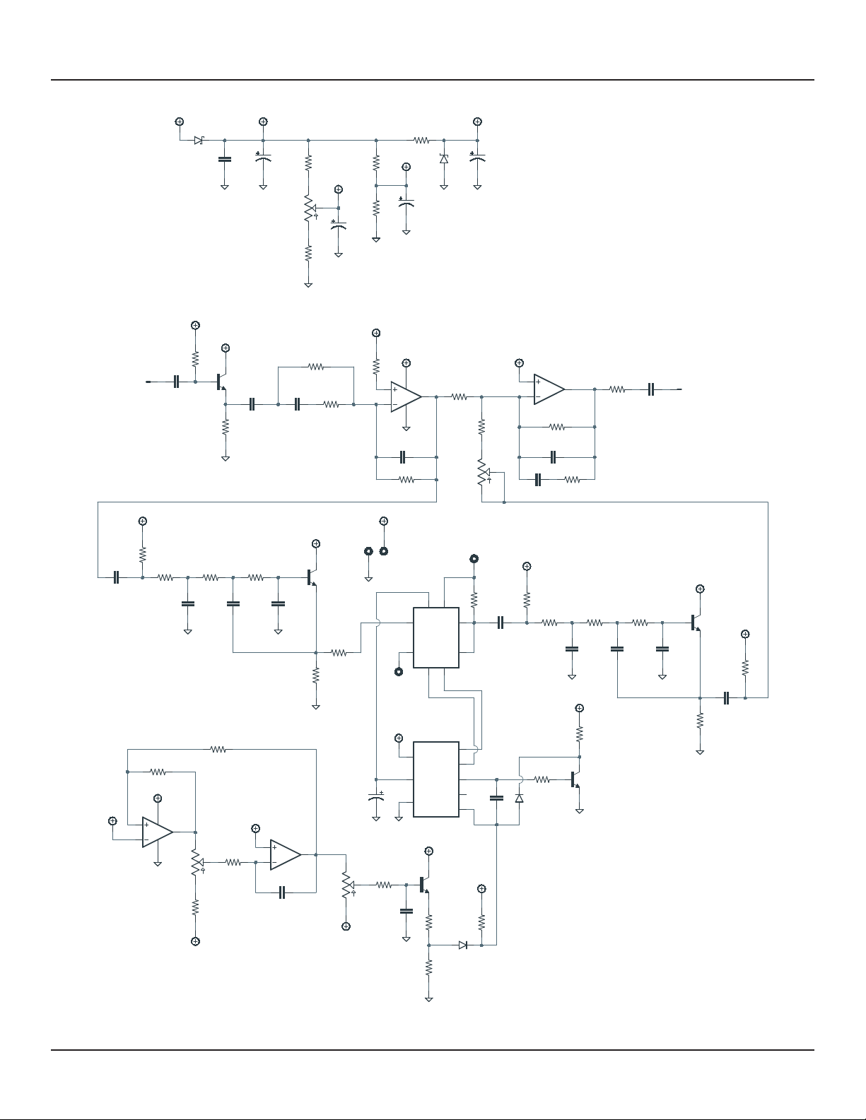
PARTS LIST, CONT.
PART VALUE TYPE NOTES
R33 1M Metal film resistor, 1/4W
R34 220k Metal film resistor, 1/4W
R35 4k7 Metal film resistor, 1/4W
R36 4k7 Metal film resistor, 1/4W
R37 4k7 Metal film resistor, 1/4W
R38 4k7 Metal film resistor, 1/4W
R39 10k Metal film resistor, 1/4W
R40 10k Metal film resistor, 1/4W
R41 33R Metal film resistor, 1/4W
RPD 2M2 Metal film resistor, 1/4W Input pulldown resistor. Can be as low as 1M.
LEDR 4k7 Metal film resistor, 1/4W LED current-limiting resistor. Adjust value to change LED brightness.
C1 47n Film capacitor, 7.2 x 2.5mm
C2 470n Film capacitor, 7.2 x 3mm
C3 6n8 Film capacitor, 7.2 x 2.5mm
C4 100pF MLCC capacitor, NP0/C0G
C5 100pF MLCC capacitor, NP0/C0G
C6 6n8 Film capacitor, 7.2 x 2.5mm
C7 1uF Film capacitor, 7.2 x 3.5mm
C8 33n Film capacitor, 7.2 x 2.5mm
C9 3n3 Film capacitor, 7.2 x 2.5mm
C10 8n2 Film capacitor, 7.2 x 2.5mm
C11 470pF MLCC capacitor, NP0/C0G
C12 1uF Tantalum capacitor, 044A
C13 33n Film capacitor, 7.2 x 2.5mm
C14 3n3 Film capacitor, 7.2 x 2.5mm
C15 8n2 Film capacitor, 7.2 x 2.5mm
C16 470pF MLCC capacitor, NP0/C0G
C17 33n Film capacitor, 7.2 x 2.5mm CE-2B (bass version) uses 12n here.
C18 47pF MLCC capacitor, NP0/C0G
C19 100n Film capacitor, 7.2 x 2.5mm
C20 10n Film capacitor, 7.2 x 2.5mm
C21 47uF Electrolytic capacitor, 5mm Reference voltage filter capacitor.
C22 47uF Electrolytic capacitor, 5mm Reference voltage filter capacitor.
C23 220uF Electrolytic capacitor, 6.3mm Power supply filter capacitor.
C24 100uF Electrolytic capacitor, 6.3mm Power supply filter capacitor.
C25 100n MLCC capacitor, X7R Power supply filter capacitor.
Z1 1N4739A Zener diode, 9.1V, DO-41 BBD protection diode. Use 1N4743 if using MN3007.

AZURE ANALOG CHORUS 5
PARTS LIST, CONT.
PART VALUE TYPE NOTES
D1 1N5817 Schottky diode, DO-41
D2 1N914 Fast-switching diode, DO-35
D3 1N914 Fast-switching diode, DO-35
Q1 2N5088 BJT transistor, NPN, TO-92 Substitute. Original uses 2SC732TM-GR.
Q2 2N5088 BJT transistor, NPN, TO-92 Substitute. Original uses 2SC732TM-GR.
Q3 2N5088 BJT transistor, NPN, TO-92 Substitute. Original uses 2SC732TM-GR.
Q4 2N5088 BJT transistor, NPN, TO-92 Substitute. Original uses 2SC945P.
Q5 2N5088 BJT transistor, NPN, TO-92 Substitute. Original uses 2SC945P.
IC1 JRC4558D Operational amplifier, DIP8
IC1-S DIP-8 socket IC socket, DIP-8
IC2 MN3207 Bucket-brigade delay, 1024 stages The Coolaudio version of this chip is called the v3207.
IC2-S DIP-8 socket IC socket, DIP-8
IC3 MN3102 Clock driver for BBD The Coolaudio version of this chip is called the v3102.
IC3-S DIP-8 socket IC socket, DIP-8
IC4 TL022 Operational amplifier, DIP8
IC4-S DIP-8 socket IC socket, DIP-8
BIAS 10k trimmer Trimmer, 10%, 1/4” Bourns 3362P or similar.
RATE 100kB 16mm right-angle PCB mount pot
DEPTH 100kB 16mm right-angle PCB mount pot
MIX 250kC 16mm right-angle PCB mount pot
LED 5mm LED, 5mm, red diffused
IN 1/4" mono 1/4" phone jack, closed frame Switchcraft 111X or equivalent.
OUT 1/4" mono 1/4" phone jack, closed frame Switchcraft 111X or equivalent.
DC 2.1mm DC jack, 2.1mm panel mount Mouser 163-4302-E or equivalent.
FSW 3PDT Stomp switch, 3PDT
ENC 125B Enclosure, die-cast aluminum Can also use a Hammond 1590N1.

AZURE ANALOG CHORUS 6
BUILD NOTES
BBD selection
The original bucket-brigade delay chips used in the CE-2 have been discontinued for many years and
old-stock chips are getting difficult to find. Fortunately, reproductions of both the MN3007 and the
newer MN3207 are available along with the corresponding clock driver, and they perform just as well as
the original devices in this circuit.
The original CE-2 uses the MN3007 (reproductions available from Xvive), while later chorus pedals such
as the CE-3 use the MN3207 (reproductions available from Coolaudio as the v3207). The Azure project
is set up to allow either type to be used by soldering two jumpers in one configuration or another.
So which should you use? The MN3207 has slightly better noise specs, but a lower maximum operating
voltage. In this application, the maximum voltage doesn’t make much of a difference since we’re running
it at 9V either way, so the added expense of the MN3007 probably outweighs any advantage.
However, the silicon shortage that began in 2021 has made all new-production BBDs somewhat scarce
as Xvive and Coolaudio’s production has been delayed. So really, go with whatever you can find until the
shortage is over. Any BBD is better than no BBD!
Clock selection
The MN3101 clocks are only compatible with the MN3007, and the MN3102 and v3102 clocks are
only compatible with the MN3207 and v3207. There are currently no reissues or reproductions of the
MN3101, so if you use a reissue MN3007 then you’ll need an old-stock MN3101 to drive it.
These are a lot easier to find than old-stock MN3007s, but be careful to order from trusted sources
since it’s possible that a fake chip could damage the BBD.
Setting the jumpers
Underneath IC2, there are four jumper pads arranged in a square pattern. The MN3007 and MN3207
have their positive and negative supply pins inverted from each other, so the jumpers need to be set to
route the supply voltages to the correct pins.
The underside of the PCB has a legend on the silkscreen showing which way the jumpers should be
soldered. If using a MN3007, both jumpers should go horizontally. If using a MN3207 or v3207, the
jumpers should go vertically.
The MN3101 and MN3102 clock drivers have the supply pins reversed internally, so these two chips are
cross-compatible and IC3 does not require any of its own jumpers.
Setting the bias by ear
The trimmer adjusts the bias voltage to get optimum performance from the BBD. Set the Depth knob all
the way up and set Rate to a medium speed, around 12:00. Start with the bias control at halfway, then
adjust it up or down until you hear the strongest chorus and the least audible distortion.

AZURE ANALOG CHORUS 7
BUILD NOTES, CONT.
Setting the bias with an oscilloscope
If you’ve got an oscilloscope, you can look at the waveform and fine-tune the bias visually rather than by
ear. Connect the oscilloscope to the emitter of Q3 or the left leg of R24. Use a signal generator to create
a sine wave at 200 Hz, 3V peak to peak, and send this to the pedal’s input.
Adjust the bias trimmer until the waveform is equally clipped on the top and bottom. The waveform is
not symmetrical, so you’re looking for equal-width clipping but not necessarily equal-shape clipping.
The CE-2 service manual says to use a test signal amplitude of +3dBm, which should convert to
around 900mv peak to peak. However, in prototyping with a digital signal generator, we found that the
amplitude needed to be significantly higher—around 3V—to get enough clipping that it could be reliably
adjusted.
The test signal is intended to be much larger than what the pedal will deal with in normal use, so the
waveform will not clip like this in practice. It’s just easier to dial the symmetry when you’re looking for
peaks of equal width.
Bass mod
The CE-2B only has one component difference from the standard CE-2. The output capacitor of the
effect signal, C17, has been lowered from 33n to 12n in the bass version.
This cuts the bass EQ of the effect signal somewhat so that only the upper frequencies are modulated
and the lower frequencies are left untouched. In other words, bass mode has less bass while guitar mode
has more bass. This prevents the low frequencies from modulating in a way that would sound out of tune
or dissonant in a band setting.
Depth/intensity mod
C18 can be changed from 47pF to 100pF to increase the maximum modulation depth or intensity.

AZURE ANALOG CHORUS 8
SCHEMATIC
IN
OUT
7
62
58
4
3
1
VDD
CP1
VSS
CP2
OX3
OX2
OX1
VGG
1
2
4
5
6
8
3
7
1N5817
100uF
100kB
100kB
250kC
+9V
100n
GND
47n
470k
VB
VA
4k74k7
10k
GND
47uF
GND
VB
33R
GND
220uF
GND
10k10k
47uF
GND
GND
VC
VD
2N5088
VA
10k
GND
470n
6n8
10k
47k
RC4558P
10k
VB
47k
RC4558P
VA
GND
100pF
47k
VB
47k
100pF
6n8
10k
470R
1uF
33n
100k
VB
10k
3n3
10k
8n2
10k
470pF
GND GND
2N5088
VA
10k
GND
4k7
MN3102
VD
GND
1uF
GND
GND
56k
VD
33n
330k
VB
10k
3n3
GND
10k
8n2
10k
470pF
2N5088
VA
GND
10k
GND
33n
1M
VB
47k
47pF
33k 2N5088
GND
VD
2k7
1N914
150k
VD
1N914
VC
TL022
TL022
VA
GND
47k
33k
10k
VC
1M
VC
100n
VC
220k
10n
2N5088
4k74k7
GND
GND
VA
D1
C24
RATE
1
2
3
DEPTH
1
2
3
MIX
1
2
3
C25
C1
R2
R37R38
BIAS
1
2
3
C21
R41
Z
1N4738A
1
C23
R39R40
C22
Q1
R3
C2
C3
R4
R5
2
3
1
IC1A
R6
R7
84
6
5
7
IC1B
C4
R8
R9
C5
C6 R10
R11
C7
C8
R13
R14
C9
R15
C10
R16
C11
Q2
R17
R18
IC2
MN3207
IC3
C12
R19
GND/VDD
VDD/GND
C13
R20
R21
C14
R22
C15
R23
C16
Q3
R24
C17
R25
R26
C18
R27 Q4
R28
D2
R29
D3
2
3
1
IC4A
6
5
7
IC4B
84
R30
R31
R32
R33
C19
R34
C20
Q5
R35R36
GND

AZURE ANALOG CHORUS 9
DRILL TEMPLATE
Cut out this drill template, fold the edges and tape it to the enclosure. Before drilling, it’s recommended
to first use a center punch for each of the holes to help guide the drill bit.
Ensure that this template is printed at 100% or “Actual Size”. You can double-check this by measuring
the scale on the printed page.
Top jack layout assumes the use of closed-frame jacks like the Switchcraft 111X. If you’d rather use
open-frame jacks, please refer to the Open-Frame Jack Drill Template for the top side.
LED hole drill size assumes the use of a 5mm LED bezel, available from several parts suppliers. Adjust
size accordingly if using something different, such as a 3mm bezel, a plastic bezel, or just a plain LED.
ø3/8” ø1/2”
0.385”
0.625” 0.625”
x: 0, y: -1.775
ø15/32”
x: -0.775, y: -1.775
ø5/16”
ø3/8”
125B
OUT
DEPTH RATE
MIX
FOOTSWITCHLED
DC IN
x: -0.65, y: +1.71 x: 0.65, y: +1.71
ø9/32” ø9/32”
x: 0, y: +0.66
ø9/32”
CENTER (0,0)
0 1 2
CM
0 1
INCH

AZURE ANALOG CHORUS 10
ENCLOSURE LAYOUT
Enclosure is shown without jacks. See next page for jack layout and wiring.
125B

AZURE ANALOG CHORUS 11
WIRING DIAGRAM
125B
IN +VGND NC NC OUT
PCB
IN
GND +V +V JACK GND JACK
OUTIN
GND GND PCB
OUT

AZURE ANALOG CHORUS 12
LICENSE & USAGE
No direct support is offered for these projects beyond the provided documentation. It’s assumed
that you have at least some experience building pedals before starting one of these. Replacements and
refunds cannotbe offered unless it can be shown that the circuit or documentation are in error.
All of these circuits have been tested in good faith in their base configurations. However, not all the
modifications or variations have necessarily been tested. These are offered only as suggestions based
on the experience and opinions of others.
Projects may be used for commercial endeavors in any quantity unless specifically noted. No
attribution is necessary, though a link back is always greatly appreciated. The only usage restrictions
are that (1) you cannot resell the PCB as part of a kit without prior arrangement, and (2) you cannot
“goop” the circuit, scratch off the screenprint, or otherwise obfuscate the circuit to disguise its source.
(In other words: you don’t have to go out of your way to advertise the fact that you use these PCBs, but
please don’t go out of your way to hide it. The guitar effects industry needs more transparency, not less!)
DOCUMENT REVISIONS
1.0.0 (2021-11-26)
Initial release.
Table of contents
Other aion Music Pedal manuals

aion
aion POLYPHEMUS User manual

aion
aion Lab Series User manual

aion
aion CRESCENT AMP DISTORTION User manual

aion
aion HORIZON User manual

aion
aion MAELSTROM User manual

aion
aion UBE SCREAMER User manual

aion
aion Minima User manual

aion
aion NYSIAD Silicon Fuzz User manual

aion
aion Particle User manual

aion
aion Cadmus User manual

aion
aion FRACTAL PARAMETRIC OVERDRIVE User manual

aion
aion STRATUS User manual

aion
aion Flare User manual

aion
aion Arcturus User manual

aion
aion GLADIUS User manual

aion
aion CONSTELLATION User manual

aion
aion HALO User manual

aion
aion Onyx User manual

aion
aion SKYWAVE User manual

aion
aion PLASMA VINTAGE DRIVE User manual