manuals.online logo
Brands
  1. Home
  2. •
  3. Brands
  4. •
  5. Midland
  6. •
  7. Car Receiver
  8. •
  9. Midland ALAN-42 DS Guide

Midland ALAN-42 DS Guide

Adjustment Procedures for the ALAN-42 DS
1.Band setting for the production mode.
1).Turn off the radio.
2).Make Link for production mode as below.
Link S1 S2 S3 S4 Results
13 1 1 1 1 Production Mode For factory
3).Press the SCAN + AM/FM key and hold.
4).Turn on the radio.
5).The radio go to production mode. At this time the LCD display” Pd” display on the LCD, and go to Channel 1.
6). Turn off the radio.
7). Make Link as below to shipment for the default band.
Link S1 S2 S3 S4 Results
1 0 0 0 0 I, I2, d4, EU, EC, E, F, PL, UK Default band
8). Turn on the radio to adjustment.
Even if link to default band, keep the production mode until factory reset.
1-1. Table of Link.
Link S1 S2 S3 S4 Results
1 0 0 0 0 I, I2, d4, EU, EC, E, F, PL, UK Default band
2 0 0 0 1 I, I2, d4, EU, EC, E, F, PL, UK, PX
3 0 0 1 0 I, I2, d4, EU, EC, E, F, PL, UK, RU
4 0 0 1 1 I, I2, d4, EU, EC, E, F, PL, UK, PX, RU
5 0 1 0 0 Only KSA
6 0 1 0 1 Only EC
7 0 1 1 0 AU, AM
8 0 1 1 1 I, I2, d4, EU, EC, E, F, PL, UK, PX, RU, SW, AU, NZ
9 1 0 0 0 Only RU
10 1 1 0 0 RU, PC
11 1 1 0 1 Only E
12 1 1 1 0 Only NZ
13 1 1 1 1 Production Mode For factory
"0" = closed, "1" = open
1-2. Link for the Romania.
1).Description for this link.
-. Disable the power save function
-. Change the backlight function.
2).Enable for the Romania.
-. R852 : Install 0R or solder short.
3).Link (R852) Location.
2.Adjustment Procedures
2-1.Frequency table of the production mode
CH No.
Display
Frequency
(MHz) Remark
1 26.965
2 26.975
3 26.985
19 27.185
20 27.205
21 27.215
38 27.385
39 27.395
40 27.405
41 26.565
60 26.755
80 26.955
1u 27.60125
20u 27.79125
40u 27.99125
1A 25.615
2A 25.625
3A 25.635
38L 30.085
39L 30.095
40L 30.105
1E 27.415 For the VCO Adjustment
2-2.Adjustment Location.
2-3.VCO Adjustments
Adjustment Adjustment Condition Unit Value Location Adjust Point
VCO Lock
Voltage
1).Select Channel : 1E (27.415MHz)
2).At RX mode V 1.0V±0.1 TP501 TC502
2-4.Transmitter Adjustments
Adjustment Adjustment Condition Unit Value Adjust Point
Output Power (4W)
1).Select the channel : 41 (26.565MHz)
2). Enable High power
3).Select FM by AM/FM switch
4).Press PTT key
5).Select channel 40 and check
6).Select channel 1 and check.
7).Select channel 40U and check.
8).Select channel 1A and check
19).Select channel 40L and check.
W Follow Spec. RV202
Harmonics
1).Select the channel : 41 (26.565MHz)
2). Enable High power
3).Select FM by AM/FM switch
4).Press PTT key
5).L212 : Shift up side to Main Body.
6).L210 : Shift down side to Main Body.
7).Select channel 40 and check.
8).Select channel 40U and check.
dBm Follow Spec.
L211
L212
L210
Output Power (1W)
1).Select the channel : 1 (26.965MHz)
2).Enable Low power
3).Select FM by AM/FM switch
4).Press PTT key
W Follow Spec. Check only
Frequency
1).Select the channel : 1 (26.965MHz)
2). Enable High power
3).Select FM by AM/FM switch
4).Press PTT key
Hz Follow Spec. TC501
Frequency
(UK band)
1).Select the channel : 1U (27.60125MHz)
2). Enable High power
3).Press PTT key
Hz Follow Spec. Check only
AM Modulation (4W)
1).Select the channel : 1 (26.965MHz)
2). Enable High power
3).Select AM by AM/FM switch
4).Press PTT key
% Follow Spec. RV203
AM Modulation (1W)
1).Select the channel : 1 (26.965MHz)
2).Enable Low power
3).Select AM by AM/FM switch
4).Press PTT key
% Follow Spec Check only
FM max Deviation
1).Select the channel : 41 (26.565MHz)
2). Enable High power
3).Select FM by AM/FM switch
4).Press PTT key
5).Select channel 1 and check
6).Select channel 40 and check.
7).Select channel 40U and check
KHz 1.7
(Follow Spec) RV501
Signal Meter (4W)
1).Select the channel : 1 (26.965MHz)
2). Enable High power
3).Select FM by AM/FM switch
4).Press PTT key
Bar 5Bar(4W) RV201
Signal Meter (1W)
1).Select the channel : 1 (26.965MHz)
2). Enable Low power
3).Select FM by AM/FM switch
4).Press PTT key
Bar 2Bar(1W) Check only
4.Receiver Adjustments
Adjustment Adjustment Condition Unit Value Adjust Point
AM Max Audio and
Distortion
1).Select the channel : 20 (27.205MHz)
2).Select AM by AM/FM switch
3).SG level : -47dBm
V
% Follow Spec Check only
AM Sensitivity
1).Select the channel : 20 (27.205MHz)
2).Select AM by AM/FM switch
3).SG level : -107dBm
4).Select channel 1 and check.
5).Select channel 40 and check.
dBm Follow Spec Check only
FM Max Audio and
Distortion
1).Select the channel : 20 (27.205MHz)
2).Select FM by AM/FM switch
3).SG level : -47dBm
V
% Follow Spec Check only
FM Sensitivity
1).Select the channel : 20 (27.205MHz)
2).Select FM by AM/FM switch
3).SG level : -107dBm
4).Select channel 1 and check.
5).Select channel 40 and check.
6).Select channel 41 and check.
7).Select channel 1U and check.
8).Select channel 40U and check.
9).Select channel 1A and check.
10).Select channel 40L and check.
dBm Follow Spec Check only
Tight Squelch
1).Select the channel : 20 (27.205MHz)
2).Select FM by AM/FM switch
3).SG level : -47dBm
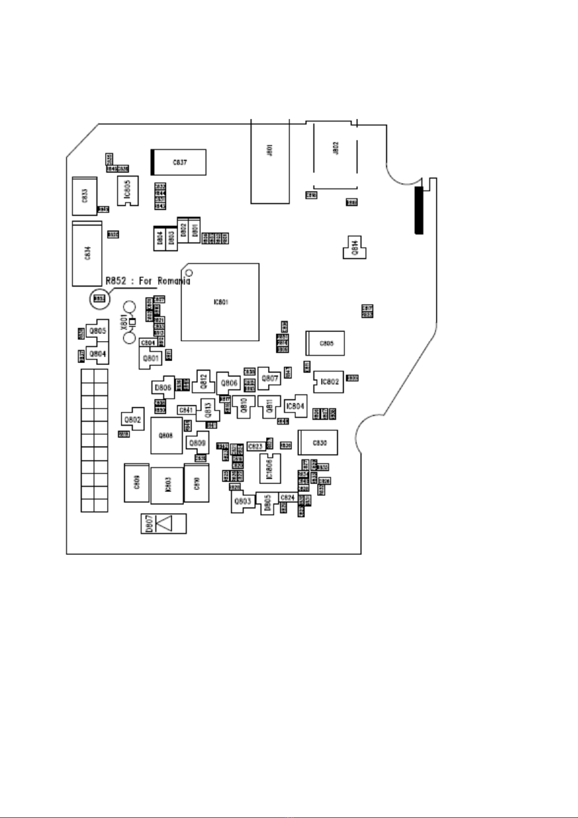
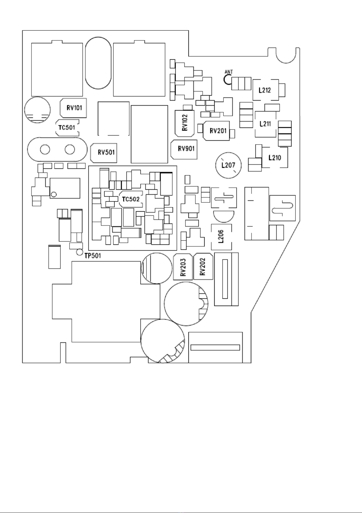
dBm Follow Spec RV101
Auto Squelch
1).Select the channel : 20 (27.205MHz)
2).Select AM by AM/FM switch
3).SG level : Depend on sensitivity
dB Follow Spec RV901
Signal Meter
1).Select the channel : 20 (27.205MHz)
2).Select FM by AM/FM switch
3).SG level : -67dBm
Bar Follow Spec RV102
NB (Noise Blank)
1). Select the channel : 20 (27.205MHz)
2).Select AM by AM/FM switch
3).Enable NB
.Press long SCAN key
.Will be blanking AM / FM icon on the LCD
4).SG level : -101dBm
5).Disable NB
.Press long SCAN key
dB Follow Spec Check only
5.Factory Reset before shipment.
Must be factory reset the ALAN-42 DS before shipment.
The factory reset method as below.
1).Turn off the radio
2).Setting default link as below
3).Press the SCAN + EMG key and hold.
4).Turn on the radio
5).Completed factory reset, on the LCD display show the band “EC” and channel “1”
*.Note
1.Band Selection.
1).Turn off the radio
2).Press SCAN + AM/FM key and hold.
3).Turn on the radio.
4).Select the band via Up and Down key.
5).Press the AM/FM key to confirm.
Link S1 S2 S3 S4 Results
1 0 0 0 0 I, I2, d, d2, d3, d4, EU, EC, E, F, PL, UK Default band
6.Assemble notice.
1). VCO Can Soldering Point to avoid TX O.S.C when high power.
2). Main body to PCB ground soldering and add shield plate to solve TX harmonics.
3). Main body to ground soldering for ACP in AM with DC car adaptor.
4). Main body to DC ground terminal soldering for ACP in AM with DC car adaptor.
5). Assemble DC car adaptor for ACP in AM.
7. Assemble Picture.

Popular Car Receiver manuals by other brands

Kenwood KDC-2027SG instruction manual

Kenwood

Kenwood KDC-2027SG instruction manual

Pioneer DEH-P55BT Operation manual

Pioneer

Pioneer DEH-P55BT Operation manual

Eonon G2226 user manual

Eonon

Eonon G2226 user manual

Pyle PLCDCS 200 owner's manual

Pyle

Pyle PLCDCS 200 owner's manual

Soundstream VR-651 B owner's manual

Soundstream

Soundstream VR-651 B owner's manual

Panasonic CQ-DFX202N operating instructions

Panasonic

Panasonic CQ-DFX202N operating instructions

Eclipse E-iSERV CD3200 user manual

Eclipse

Eclipse E-iSERV CD3200 user manual

Medion MD 4295 manual

Medion

Medion MD 4295 manual

JVC GET0117-003B Installation & connection manual

JVC

JVC GET0117-003B Installation & connection manual

TOP VEHICLE TECH KWFIA1 installation manual

TOP VEHICLE TECH

TOP VEHICLE TECH KWFIA1 installation manual

Alpine cda-7840 owner's manual

Alpine

Alpine cda-7840 owner's manual

JVC KD-R306 instructions

JVC

JVC KD-R306 instructions

JVC KD-AR8500J Installation & connection manual

JVC

JVC KD-AR8500J Installation & connection manual

Blaupunkt Brisbane SD48 Operating and installation instructions

Blaupunkt

Blaupunkt Brisbane SD48 Operating and installation instructions

Kenwood KDC-U7053BT instruction manual

Kenwood

Kenwood KDC-U7053BT instruction manual

Dual DSA2062 Installation & owner's manual

Dual

Dual DSA2062 Installation & owner's manual

Kenwood DDX7025 installation manual

Kenwood

Kenwood DDX7025 installation manual

Pioneer SUPER TUNER IIID DEH-1900MP Operation manual

Pioneer

Pioneer SUPER TUNER IIID DEH-1900MP Operation manual

manuals.online logo
manuals.online logoBrands
  • About & Mission
  • Contact us
  • Privacy Policy
  • Terms and Conditions

Copyright 2025 Manuals.Online. All Rights Reserved.