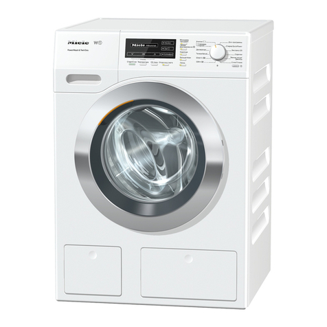
Miele PWM 916 SD User manual

PWM916 SD/SI
en Installation Plan Commercial Washing Machine
fr Schéma d’installation Machine à laver professionnelle
M.-Nr. 12 175 450

en - Contents
3
Installation and planning notes...................................................................................... 4
Installation requirements ................................................................................................... 4
General operating conditions ............................................................................................ 4
Installation ......................................................................................................................... 4
Installation on concrete base ........................................................................................ 4
Leveling the machine......................................................................................................... 5
Securing the machine........................................................................................................ 5
Electrical connection......................................................................................................... 5
Water connection .............................................................................................................. 7
Cold-water connection.................................................................................................. 7
Hot water connection.................................................................................................... 7
Drain valve..................................................................................................................... 8
Dispenser pump connections ........................................................................................... 8
Optional accessories......................................................................................................... 10
Payment system kit (BSK) ............................................................................................. 10
Peak-load negotiation kit (BSS)..................................................................................... 10
XKM RS232 communication module ............................................................................ 11
Hard-water kit (APWM062)............................................................................................ 11
Plinth (UO/UG)............................................................................................................... 11
Vapor and suds venting kit (APWM063)....................................................................... 11
PWM916 .......................................................................................................................... 12
Dimensions........................................................................................................................ 12
Standard........................................................................................................................ 12
Installation ......................................................................................................................... 13
Standard........................................................................................................................ 13
Floor anchoring ................................................................................................................. 15
Technical data ................................................................................................................... 16
Electrical version and electrical data............................................................................. 16
Water connection .......................................................................................................... 16
Drainage ........................................................................................................................ 16
Connection for equipotential bonding........................................................................... 16
Installation dimensions.................................................................................................. 16
Anchoring ...................................................................................................................... 17

Transport data, weight and floor load ........................................................................... 17
Emissions data .............................................................................................................. 17

en - Installation and planning notes
4
Installation requirements
The washing machine must be installed by Miele Service or by
properly trained staff of an authorized dealer.
This washing machine must be installed in accordance with all rel-
evant regulations and standards. Local energy supplier regulations
must also be observed.
This washing machine must only be operated in a room that has
sufficient ventilation and which is frost-free.
The washing machine should not be installed or operated in any
area where there is a risk of explosion.
General operating conditions
This washing machine is intended only for use in a commercial envi-
ronment and must only be operated indoors.
- Ambient temperature: 32-105°F (0-40°C)
- Relative humidity: non-condensing
- Maximum height above sea level of location site: 6500 ft (2000 m)
Depending on the nature of the installation site, sound emissions and
vibration may occur.
Tip: Have the installation site inspected and seek the advice of a spe-
cialist in instances where increased noise may cause a nuisance.
Installation
The washing machine must be set up on a level and firm surface with
the minimum stated load bearing capacity (see “Technical data”).
The floor load created by the washing machine is concentrated and
transferred to the installation footprint via the machine feet.
Tip: A concrete floor is the most suitable installation surface for this
appliance. It is far less prone to vibration during the spin cycle than
wooden floorboards or a carpeted surface.
The washing machine requires a gap of at least 2" (50mm) at each
side to allow for movement during operation. To ensure suitable ac-
cess for further maintenance and service work, please ensure a mini-
mum distance of 16" (400mm) is maintained between the back of the
machine and the wall.
Machines with an integrated sampling valve must have a gap of at
least 8" (200mm) on the left hand side.
Installation on
concrete base
The washing machine can be installed on a concrete base if desired.
The concrete materials and the durability of the concrete base must
be assessed in accordance with the floor load bearing capacity
given in “Technical data”.

en - Installation and planning notes
5
To guarantee the stability of the washing machine, make sure that
the concrete base is sufficiently stable on the floor and that it is ca-
pable of withstanding any burden or force from the washing ma-
chine.
The washing machine must be secured to the concrete base using
the fixtures and fastenings supplied.
The washing machine must be secured to the base immediately
after installation!
There is a risk of the washing machine falling off a raised base dur-
ing a spin cycle if it is not secured.
Leveling the machine
Align the washing machine vertically and horizontally using the ad-
justable feet and a level.
The washing machine must stand perfectly level on all four feet to
ensure safe and proper operation. Otherwise water and energy con-
sumption will be increased and the machine could move.
After aligning the machine tighten the lock nuts by turning them in a
counterclockwise direction with a wrench. This will prevent the feet
from moving.
Securing the machine
The feet of the washing machine must be secured to the concrete
base using the fixtures and fastenings supplied.
Fittings supplied are for installation on a concrete floor. For other
types of flooring please purchase suitable fitting materials sepa-
rately.
Electrical connection
The electrical connection must only be carried out by a qualified
electrician who must ensure that all electrical work is carried out in
accordance with applicable electrical regulations and standards.

en - Installation and planning notes
6
The washing machine must be connected to an electrical supply
that complies with local and national regulations. Please also observe
your insurance and energy supplier's regulations as well as any health
and safety at work regulations.
The required voltage, power consumption and specifications for
external fusing are quoted on the data plate on the washing machine.
Ensure that the supply voltage complies with the voltage quoted on
the data plate before connecting the washing machine to the power
supply.
Connection to a supply voltage other than the one quoted on the
data plate can lead to functional faults and damage the washing
machine.
If more than one voltage is quoted on the data plate, the washing
machine can be converted for connection to the voltages stated.
Conversion to a different voltage must only be carried out by a
Miele Service engineer or by an authorized Service Dealer. The wiring
instructions given on the wiring diagram must be followed.
The washing machine can either be hard-wired or connected via a
plug and socket that complies with national codes and regulations.
For a hard-wired connection an all-pole isolation device must be in-
stalled on site.
For hard-wired machines connection should be made via a suitable
switch with all-pole isolation which, when in the off position, ensures
a 1/8" (3 mm) gap between all open contacts. These include circuit
breakers, fuses and relays.
If the power supply cannot be permanently disconnected, the isolator
switch (including plug and socket) must be safeguarded against be-
ing switched on either unintentionally or without authorization.
Tip: We recommend connection to the power supply via a suitable
plug and socket which must be easily accessible for servicing and
maintenance work after the machine has been installed.
If it is necessary to install a residual current device (RCD) in accor-
dance with local regulations, a typeB residual current device (sensi-
tive to universal current) must be used.
An existing typeA residual current device (RCD) must be exchanged
for a typeB RCD.
If necessary, equipotential bonding with good galvanic contact
must be guaranteed in compliance with all applicable local and na-
tional installation specifications.
Equipotential bonding must have an ground current rating >10mA.
Accessories for equipotential bonding are not supplied and need to
be ordered separately.

en - Installation and planning notes
7
Water connection
According to national regulations for drinking water quality, with ef-
fect from March 21, 2021, a non-return valve to prevent backsiphon-
ing must be installed between the faucet and the water inlet hose
during commissioning on all machines in Germany. The non-return
valve prevents water from the water inlet hose from flowing back
into the on-site drinking water supply.
Non-return valves are supplied.
The flow pressure must amount to a minimum of 100kPa (14.5psi)
and must not exceed an overpressure of 1,000kPa (145psi). If the
flow pressure is higher than 1,000kPa (145psi), a pressure reducing
valve must be used.
The machine must be connected to the water connection using the
water inlet hoses provided.
The connection points are subject to water connection pres-
sure.
Turn on the water supplies slowly and check for leaks. Correct the
position of the seal and screw thread if appropriate.
Cold-water con-
nection
For the cold-water connection one shut-off valve each with a
¾" external thread is required. A connector (Y-piece) can be used if
required to connect 2water inlet hoses with a ¾" screw thread to a
single faucet with a 1" male thread.
The water inlet hose for cold water (blue stripes) is not intended to
be used with a hot-water connection.
Hot water con-
nection To minimize energy consumption during operation with hot water,
the washing machine should be connected to a suitable hot water
ring circuit if present.
So-called “transmission lines” (single lines to hot water generators)
can result in cooling down of the water remaining in the pipes if not
in constant use. More electrical energy would be needed in order to
heat the suds.
Use the water inlet hose supplied (red stripes) for the hot water con-
nection.
The temperature of the water intake must not exceed 158°F (70°C)
on machines with electric heating(EL).
The temperature of the water intake must not exceed 194°F (90°C)
on machines without heating(OH).
The machine must be connected to the water supply using the inlet
hoses provided.

en - Installation and planning notes
8
If there is no hot water supply at the installation location, the inlet
hose for hot water must also be connected to the cold water supply.
An additional Y-piece is required in this case. Cold water consump-
tion increases accordingly to account for the missing hot water in-
take.
For functional and technical reasons it is not possible to operate
the machine exclusively with a hot water connection.
Even if a hot water connection is present, the washing machine
must be connected to a cold water intake.
Drain valve A motorized dump valve is used to drain the machine. An HTDN70
angle connector can be used for draining the machine directly into
the waste water system (without a siphon) or into an on-site gully
(with odor trap).
A vented drainage system is vital for unimpeded drainage.
If several machines are connected to a single drain pipe, this
should be sufficiently large to allow all machines to drain simultane-
ously.
The appropriate Mieleinstallation kit mat. no.:05238090 is avail-
able from Miele or Miele Technical Service for venting an
HTDN70pipe.
If the slope for drainage is extremely steep, the piping must be
vented to prevent formation of a vacuum in the machine’s drain
system.
Slow or obstructed drainage or a backup of water in the drum as a re-
sult of undersized pipework can result in faults occurring during pro-
gram sequences, which will result in error messages appearing in the
display.
Risk of burning due to hot suds.
Outflowing suds can be as hot as 203°F (95°C).
Avoid direct contact.
Dispenser pump connections
Up to 12dispenser pumps can be connected to the washing ma-
chine.

en - Installation and planning notes
9
Dispenser pump connections on the back of the machine
Connections 1 and 2 are provided for viscous agents and can also be
used for high-pressure dispensing systems with water injection. The
dispensing systems must be fitted with a separate drinking water
safety feature in accordance with EN61770 and EN1717. The maxi-
mum flow rate is 1500ml/min with a maximum flow pressure 43 psi
(300 kPa).
These connectors are sealed and need to be drilled open using an
8mm drill bit before connecting.
Care must be taken to drill through the first wall only (I) as there is a
deflecting panel(II) 3/8"(10mm) behind it.
Connections3 to 12 are provided for liquid detergent. High-pressure
dispensing systems with water injection must not be connected to
these connections. These connectors are sealed and must be cut to
the diameter of the hose with a small saw prior to being made.
If opened connectors are no longer required, they must be resealed
using a suitable sealant (e.g., silicone).
Connection terminals for five time-controlled dispenser pumps, which
can be operated without a multifunction module, are located behind
the cover adjacent to the electrical connection.
Calibration of the dispenser pumps and regulation of dispensing
quantities is carried out semi-automatically for washing machines
fitted with an optional multifunction module. Information regarding
settings is given in the operating instructions.

en - Installation and planning notes
10
A flowmeter or flow sensors can be connected for precise monitoring
of the dispensing quantity.
Connections for level monitoring are available for every agent dis-
pensed.
Optional accessories
Only use genuine Miele parts and accessories with this machine.
Using spare parts or accessories from other manufacturers will
void the warranty, and Miele cannot accept liability.
Payment system
kit (BSK)
The washing machine can be equipped with a payment system (e.g.,
for self-service operations) using the optional BSK payment system
kit. This must be connected and programmed by Miele Technical Ser-
vice. Payment systems with mechanical or electronic coin validator
are available from Miele as optional accessories for individual target
groups.
The programming required for connecting a payment system must
be carried out by Miele Technical Service or an authorized
Mieledealer only. An external power supply is not required for a pay-
ment system.
Peak-load negoti-
ation kit (BSS)
The washing machine can be connected to an energy management
system via a peak-load negotiation kit which is available as an op-
tional accessory.
Peak-load negotiation monitors the energy consumption of a system
and deactivates individual pieces of equipment temporarily in order
to ensure that certain total load limits are not exceeded. Monitoring
is externally controlled.
The kit provides three signal contacts and a neutral conductor via a
terminal block. The terminal block is marked with “a”, “b”, “c”, and
“d”:
aOutput signal, start of machine operation
bOutput signal, machine heating request
cPeak-load input signal, machine heating deactivated
dNeutral conductor

en - Installation and planning notes
11
When the peak-load function is activated the current program is
stopped and a message appears in the display on the washing ma-
chine. The program is resumed automatically when the peak-load
system reactivates the heating.
XKM RS232 com-
munication mod-
ule
The serial interface RS-232 can be retrofitted to the washing machine
via an XKMRS232 (optional accessory available from Miele). This
communication module must only be used with MieleProfes-
sionalmachines that are fitted with an appropriate slot for the mod-
ule.
The data interface provided via communication module
XKMRS232 complies with SELV (Safety Extra Low Voltage) in ac-
cordance with EN60950.
Machines connected to this interface must also be SELV compliant.
Communication module XKMRS232 is supplied with a connection
cable and a D-sub-connector.
Hard-water kit
(APWM062)
The hard-water connection on the washing machine can be retrofitted
with the optional hard-water kit (APWM062).
The additional water connection allows hard water to be used and
the program runtime will therefore be reduced. In addition, hard wa-
ter is particularly suitable for the final rinse cycles.
Plinth (UO/UG) The machine can be installed on a machine base (open or box base,
available as an optional Miele accessory).
Elevating the washing machine gives a better ergonomic working
position when loading or unloading. At the same time it facilitates
the installation of a drain connection.
The washing machine must be secured to the base immediately
after installation! The base must be secured to the floor!
There is a risk of the washing machine falling off a raised base dur-
ing a spin cycle if it is not secured.
Vapor and suds
venting kit
(APWM063)
If excessive suds form, suds may escape from the vapor vent. The
optional vapor and suds venting kit (BWS) can be used to remove the
suds.

en - PWM916
12
Dimensions
Standard

en - PWM916
13
Installation
Standard
aElectrical connection
bCold-water connection
cHot-water connection
dHard-water connection (cold) (optional)
eCold-water connection for liquid dispens-
ing
lDrain valve
nConnection SI inlet, only steam
oConnection SI drainage, only steam
rSteam valve, only steam

en - PWM916
14
aElectrical connection
bCold-water connection
cHot-water connection
dHard-water connection (cold) (optional)
eCold-water connection for liquid dispens-
ing
fConnection for peak-load negotiation
gOverflow
hConnection for Connector Box
iConnection for Connector Kit (optional)
jConnection LAN
kConnector Box (optional)
lDrain valve
mConnection for equipotential bonding
nConnection SI inlet, only steam
oConnection SI drainage, only steam
qConnection steam, only steam
rSteam valve, only steam
sConnection for water recovery (optional)

en - PWM916
15
Floor anchoring
Standard
Multiple side-by-side installation

en - PWM916
16
Technical data
Electrical version and electrical data
Connection voltage 208/240 V3 Ph
Frequency 60 Hz
Total amps. 3 X 8.2 A
Max. fuse (time delay fuse) 3 X 8.2 A
Mimimum circuit ampacity 3 X 15 A
Water connection
Models with detergent drawer (DD)
Permitted flow pressure 145 psi (1000 kPa)
Maximum water intake rate 47.5 l/min
Cold-water connection
(to be provided on site, male thread according to DIN44991, flat seal)
3 x ½" with ¾" thread connection
Optional cold-water connection for liquid dispensing
(to be provided on site, male thread according to DIN44991, flat seal)
Optional hard-water connection, cold
(on-site external thread according to DIN44991, flat seal)
2 x ½" with ¾" thread connection (Optional)
Hot-water connection(≤158°F (70°C))
(on-site external thread according to DIN44991, flat seal)
1 x ½" with ¾" thread connection
Length of water-inlet hoses supplied 5' 1" (1.55 m)
Drainage
Maximum drain water temperature 203°F (95°C)
Waste water connection (on machine) Plastic pipe HTDN 70
Drain (on site) ConnectionDN 70
Maximum drainage rate 200 l/min
Connection for equipotential bonding
Male thread M10
Toothed washers M10
Installation dimensions
Casing width (without add-on components) 36 1/4" (920 mm)
Casing height (without add-on components) 56 3/8" (1432 mm)
Casing depth (without add-on components) 29 11/16" (754 mm)
Overall machine width 36 3/8" (924 mm)
Overall machine height 56 15/16" (1447 mm)
Overall machine depth 37 1/2" (953 mm)
Minimum width of transport opening 40 3/16" (1020 mm)
Minimum distance between wall and front of machine 50 3/8" (1280 mm)
Door-opening diameter 16 5/16" (415 mm)
Door-opening angle 180°

en - PWM916
17
Anchoring
Standard
Required anchor points 2
DIN571 wood screw (diameterxlength) 1/2" x 31/2" (12mm x 90mm)
Rawl plugs (diameterxlength) 5/8" x 31/8" (16mm x 80 mm)
With plinth (UO/UG)
Required anchor points 4
DIN571 wood screw (diameterxlength) 1/2" x 31/2" (12mm x 90mm)
Rawl plugs (diameterxlength) 5/8" x 31/8" (16mm x 80 mm)
Concrete plinth
Required anchor points 2
DIN571 wood screw (diameterxlength) 1/2" x 31/2" (12mm x 90mm)
Rawl plugs (diameterxlength) 5/8" x 31/8" (16mm x 80 mm)
Transport data, weight and floor load
Models with detergent drawer (DD)
Packaging width 43" (1090 mm)
Packaging height 62 3/8" (1585 mm)
Packaging depth 44 1/2" (1130 mm)
Gross volume 1952 l
Gross weight* 822.3 - 895.1 lb (373 - 406 kg)
Net weight* 771.6 - 844.4 lb (350 - 383 kg)
Maximum floor load during operation 5091 N
*depending on equipment configuration
Emissions data
Workplace-related sound pressure level, washing 51 dB (A)
Sound power level, washing 60.0 dB (A)
Workplace related sound pressure level, spinning 65 dB (A)
Sound power level, spinning 77.0 dB (A)
Average heat dissipation rate to installation site 6.48 MJ/h

fr - Table des matières
18
Conseils d'installation et de planification ..................................................................... 19
Conditions d'installation.................................................................................................... 19
Conditions de fonctionnement générales ......................................................................... 19
Installation ......................................................................................................................... 19
Montage sur un socle en béton..................................................................................... 20
Ajustement ........................................................................................................................ 20
Fixation.............................................................................................................................. 20
Branchement électriques .................................................................................................. 21
Raccordement à l’eau ....................................................................................................... 22
Raccordement à l’eau froide ......................................................................................... 22
Raccordement à l’eau chaude ...................................................................................... 23
Vanne de vidange.......................................................................................................... 23
Raccordements pour pompes de dosage......................................................................... 24
Options/Accessoires en option....................................................................................... 25
Kit de monnayeur (BSK) ................................................................................................ 25
Kit de gestion des charges de pointe (BSS).................................................................. 25
Module de communication XKM RS232 ....................................................................... 26
Kit de raccordement à l’eau dure (APWM062) .............................................................. 26
Socle (UO/UG)............................................................................................................... 26
Kit d’évacuation de vapeur et de mousse (APWM063)................................................ 27
PWM916 .......................................................................................................................... 28
Dimensions........................................................................................................................ 28
Standard........................................................................................................................ 28
Installation ......................................................................................................................... 29
Standard........................................................................................................................ 29
Ancrage au sol................................................................................................................... 31
Caractéristiques techniques.............................................................................................. 32
Variantes de tension et caractéristiques électriques..................................................... 32
Raccordement à l'eau ................................................................................................... 32
Vidange ......................................................................................................................... 32
Raccordement pour liaison équipotentielle................................................................... 32
Dimensions d’installation .............................................................................................. 32
Fixation.......................................................................................................................... 33
Données de transport, poids et charge au sol .............................................................. 33
Données d’émissions .................................................................................................... 33

fr - Conseils d'installation et de planification
19
Conditions d'installation
Le lave-linge ne doit être installé et mis en service que par le ser-
vice après-vente ou le personnel dûment formé d'un revendeur
agréé par la marque.
Le lave-linge doit être installé selon les directives et normes en vi-
gueur. Par ailleurs, les directives du fournisseur d'énergie et de la
compagnie des eaux du site doivent être respectées.
Utilisez uniquement le lave-linge dans des pièces suffisamment aé-
rées et non exposées au gel.
Le lave-linge ne convient pas à une utilisation dans des locaux ex-
posés aux risques d'explosion.
Conditions de fonctionnement générales
Cette machine à laver est conçue uniquement pour une utilisation en
intérieur et dans un environnement commercial.
- Température ambiante: 32-105°F (0-40°C)
- Humidité relative: sans condensation
- Hauteur maximale au-dessus du niveau de la mer du site de l’em-
placement: 6500 pi (2000m)
Selon la nature du site d’installation, des émissions sonores et des
vibrations peuvent survenir.
Conseil : Faire inspecter le site d’installation et faire appel à un pro-
fessionnel dans le cas où l’augmentation des émissions sonores de-
viendrait une nuisance.
Installation
La machine à laver doit être installée sur une surface plane et solide
avec la capacité de charge minimale déclarée (voir «Données tech-
niques»).
La charge sur le plancher créée par la machine à laver est concen-
trée et transférée sur l’empreinte de l’installation via les pieds de la
machine.
Conseil : Un sol en béton est la surface d’installation la mieux adap-
tée pour cet appareil. En effet, il est moins sujet aux vibrations du
cycle d’essorage que les planchers en bois ou les sols recouvertes
d’une moquette.
En raison des mouvements dynamiques lors de son fonctionnement,
la machine à laver nécessite des dimensions de chargement d’au
moins 50mm (2") de chaque côté. Pour faciliter la maintenance de la
machine, observer une distance d’au moins 400mm (16") entre le
mur et le panneau arrière.

fr - Conseils d'installation et de planification
20
Pour les machines disposant d’un robinet de prélèvement d’échantil-
lon, prévoir un espace d’au moins 200mm (8") du côté gauche.
Montage sur un
socle en béton
Le lave-linge peut être installé en option sur un socle en béton.
La qualité du béton et la solidité du socle ne béton doivent corres-
pondre à la charge au sol indiquée au chapitre «Caractéristiques
techniques».
Vérifiez que le socle en béton soit bien fixé au sol et résiste aux
charges partant du lave-linge, afin de garantir la stabilité de l'ap-
pareil.
Fixez impérativement le lave-linge à l'aide du matériel de fixation
fourni selon l'installation du socle.
Après avoir terminé l'installation, le lave-linge doit impérative-
ment être fixé sur le socle béton!
Attention! Risque que sans fixation le lave-linge bascule du socle
lors de l’essorage.
Ajustement
Ajustez le lave-linge après installation dans le sens longitudinal et
transversal à l'aide de pieds réglables et d'un niveau à bulles.
Pour garantir un fonctionnement efficace et économe en énergie, le
lave-linge doit être posé bien à l'horizontale sur ses 4pieds. Dans le
cas contraire, la consommation d'eau et d'énergie augmente et peut
provoquer un déplacement de l'appareil.
Serrez les contre-écrous après ajustement à l'aide d'une clé plate
dans le sens contraire des aiguilles d'une montre, pour que les
pieds ne puissent pas être déréglés.
Fixation
Fixez le lave-linge à l'aide du matériel de fixation fourni, au sol par
les pieds pour le stabiliser.
This manual suits for next models
1
Table of contents
Languages:
Other Miele Washer manuals

Miele
Miele W 1916 User manual

Miele
Miele PG 8581 User manual

Miele
Miele W 2129 User manual

Miele
Miele W 1945 Operating manual

Miele
Miele WWH 860 User manual

Miele
Miele WKH 130 WPS User manual

Miele
Miele W 2839I WPM User manual

Miele
Miele W 906 User manual

Miele
Miele Komfort User manual

Miele
Miele W 5740 User manual

Miele
Miele PG 8591 User manual

Miele
Miele PWM 909 SOM User manual

Miele
Miele G 7823 User manual

Miele
Miele PW 6241 EL User manual

Miele
Miele WXF 660 User manual

Miele
Miele PLW 8615 User manual

Miele
Miele WSH863 WCS User manual

Miele
Miele WWI 860 User manual

Miele
Miele WDD 131 WPS GuideLine User manual

Miele
Miele W 2653 WPS User manual