Mikroprojekt KONDOR AX User guide

KONDOR AX
Advanced System Development Board
BASIC DEMOS GUIDE
2.10.2015.
UM0028
Rev. 1.4

KONDOR AX BASIC Demos Guide
Rev. 1.4
2.10.2015.
i
Table of contents
1Introduction ......................................................................................1
2Downloading FPGA designs .............................................................1
DOWNLOADING FPGA DESIGNS FROM PC USING JTAG........................................... 1
2.1.1 TO ECP5 FPGA ....................................................................................................................... 1
2.1.2 TO SPI FLASH........................................................................................................................... 2
GENERATING FILES FOR EMBEDDED DESIGN ............................................................ 2
2.2.1 USING SLAVE SPI ..................................................................................................................... 2
2.2.2 USING JTAG ............................................................................................................................ 3
DOWNLOADING FPGA DESIGNS FROM I.MX6........................................................ 4
2.3.1 USING SLAVE SPI ..................................................................................................................... 4
2.3.2 USING JTAG ............................................................................................................................ 4
3Demos ................................................................................................5
DEMO 1/RD0012 -DOWNLOAD BITSTREAM AND BLINK LEDS................................ 5
3.1.1 HARDWARE .............................................................................................................................. 6
3.1.2 DOWNLOADING BITSTREAM USING SPI....................................................................................... 6
3.1.3 DOWNLOADING BITSTREAM USING JTAG.................................................................................... 7
3.1.4 LEDS....................................................................................................................................... 7
DEMO 2/RD0012 -READ AND WRITE MEMORY OVER PCIE..................................... 8
3.2.1 HARDWARE .............................................................................................................................. 8
3.2.2 DESIGN.................................................................................................................................... 8
3.2.3 DRIVER .................................................................................................................................... 8
3.2.4 APPLICATION............................................................................................................................ 8
DEMO 3/RD0013 -LOOPBACK TEST ON SFP GIGEOVER PCIE.............................. 10
3.3.1 HARDWARE ............................................................................................................................ 10
3.3.2 DESIGN.................................................................................................................................. 11
3.3.3 DRIVER .................................................................................................................................. 11
3.3.4 TEST ...................................................................................................................................... 12
DEMO 4/RD0014 -LOOPBACK TEST ON RMII PHY OVER PCIE............................. 13
3.4.1 HARDWARE ............................................................................................................................ 13
3.4.2 DESIGN.................................................................................................................................. 13
3.4.3 DRIVER .................................................................................................................................. 14
3.4.4 TEST ...................................................................................................................................... 14
DEMO 5/RD0015 -LOOPBACK TEST ON RMII PHY OVER EIM ............................. 15
3.5.1 HARDWARE ............................................................................................................................ 15

KONDOR AX BASIC Demos Guide
Rev. 1.4
2.10.2015.
ii
3.5.2 DESIGN.................................................................................................................................. 15
3.5.3 DRIVER .................................................................................................................................. 16
3.5.4 TEST ...................................................................................................................................... 16
DEMO 6/RD0016 -LOOPBACK TEST ON SFP GIGECONNECTED TO FMC CARD OVER
EIM 17
3.6.1 HARDWARE ............................................................................................................................ 18
3.6.2 DESIGN.................................................................................................................................. 18
3.6.3 DRIVER .................................................................................................................................. 18
3.6.4 TEST ...................................................................................................................................... 19
DEMO 7/RD0017 -LOOPBACK LVDS, VERIFY CONNECTIVITY USING LEDS............. 20
3.7.1 HARDWARE ............................................................................................................................ 20
3.7.2 DESIGN.................................................................................................................................. 20
3.7.3 DRIVER .................................................................................................................................. 20
3.7.4 TEST ...................................................................................................................................... 21
DEMO 8/RD0018 -UART AND I2C COMMUNICATION BETWEEN ARM AND ECP5.. 22
3.8.1 HARDWARE ............................................................................................................................ 22
3.8.2 DESIGN.................................................................................................................................. 22
3.8.3 DRIVER .................................................................................................................................. 22
3.8.4 UART.................................................................................................................................... 23
3.8.5 I2C........................................................................................................................................ 23
Terms of use .......................................................................................25
Contact info ........................................................................................25

KONDOR AX BASIC Demos Guide
Rev. 1.4
2.10.2015.
iii
Revision History
Revision
Date
Author
Modification
1.0
3.3.2015.
DM
Initial
1.1
10.3.2015.
DM
Added demo 7
1.2
13.3.2015.
DM
Added demos 3 and 4
1.3
25.3.2015.
DM
All demos added
1.4
21.9.2015.
NDZ
Demos description edited
Related Documents
ID
Code
Description
1
UM0026
KONDOR AX –User Manual
2
UM0027
KONDOR AX –Linux BSP Build Setup Guide
4
UM0029
KONDOR AX –Basic Demos Reference Design Guide

KONDOR AX BASIC Demos Guide
Rev. 1.4
2.10.2015.
1 / 25
1Introduction
All source code for FPGA design, drivers and demo applications is provided
separately. Compiling sources is described in Kondor Software User Guide.
2Downloading FPGA designs
While following chapters describe four possible ways to transfer designs to FPGA,
it suffices to use only one of them, most suitable for desired use.
Direct download to FPGA is useful when having multiple versions under
development.
For verified and stable designs, best choice is downloading them into SPI flash.
For designs under development or when you want to be able to switch between
several designs in short time, best choice is using slave SPI.
JTAG method (from i.MX6) is supported for completeness and seems to have no
benefits over slave SPI.
Downloading FPGA designs from PC using JTAG
To ECP5 FPGA
1. Connect micro USB cable to U33 connector on the board, install necessary
USB/serial port drivers on the PC if required.
2. Start Lattice Diamond Programmer tool and select matching
communication port for transferring data to the board.
3. Device Family should be ECP5UM; Device should be LFE5UM-85F.
4. Double click on the cell in Operation column to open Device properties
dialog box. Set Access mode to JTAG 1532 Mode; set Operation to Fast
Program.
5. Under Programming file, select the desired .bit file containing FPGA
design.

KONDOR AX BASIC Demos Guide
Rev. 1.4
2.10.2015.
2 / 25
6. Close the dialog box by clicking OK.
7. Menu Design
Program.
To SPI flash
1. Connect micro USB cable to U33 connector on the board, install necessary
USB/serial port drivers on the PC if required.
2. Start Lattice Diamond Programmer tool and select matching
communication port for transferring data to the board.
3. Device Family should be ECP5UM; Device should be LFE5UM-85F.
4. Double click on the cell in Operation column to open Device properties
dialog box. Set Access mode to SPI Flash Background Programming; set
Operation to SPI Flash Erase, Program, Verify.
5. Under Programming file, select the desired .bit file containing FPGA
design. Family should be SPI Serial Flash. Vendor is STMicro; Device is SPI-
M25P64; Package is 8-lead VDFPN8.
6. Load from File start and end addresses.
7. Close the dialog box by clicking OK.
8. Menu Design
Program.
Note: since the design is saved into flash memory, it will "survive" board resets
and shutdowns.
Generating files for embedded design
Using Slave SPI
Start Lattice Diamond Programmer tool. The USB cable is not required.
1. Set Device Family to ECP5UM; set Device to LFE5UM-85F.
2. Double click on the cell in Operation column to open Device properties
dialog box. Set Access mode to Slave SPI Interface Programming; set
Operation to Slave SPI Fast Program.
3. Select desired .bit file as usual.
4. File
Save Untitled As, save an .xcf file into a desired folder.
Start Lattice Diamond Deployment Tool.

KONDOR AX BASIC Demos Guide
Rev. 1.4
2.10.2015.
3 / 25
1. Create New Deployment.
2. Set Function Type to Embedded System; set Output File Type to Slave SPI
Embedded. Click OK.
3. Turn on the check mark Input XCF File. Select previously saved .xcf file.
Click Next.
4. Compress embedded files should be selected. Next.
5. Optionally change folder, and give recognizable names to algorithm and
data file. Next.
6. Generate.
Using JTAG
Start Lattice Diamond Programmer tool. The USB cable is not required.
1. Set Device Family to ECP5UM; set Device to LFE5UM-85F.
2. Double click on the cell in Operation column to open Device properties
dialog box. Set Access mode to JTAG 1532 Mode; set Operation to Fast
Program.
3. Select desired .bit file as usual.
4. Menu File
Save Untitled As, save an .xcf into a desired folder.
Start Lattice Diamond Deployment Tool.
1. Create New Deployment.
2. Set Function Type to Embedded System; set Output File Type to JTAG Full
VME Embedded. Click OK.
3. Turn on the check mark Input XCF File. Select previously saved .xcf file.
Click Next.
4. Compress VME File and Include Header should be selected. Next.
5. Optionally change folder, and give recognizable name to output file. Next.
6. Generate.

KONDOR AX BASIC Demos Guide
Rev. 1.4
2.10.2015.
4 / 25
Downloading FPGA designs from i.MX6
Using Slave SPI
Connect a micro USB cable to U24 connector. Board should be recognized as
virtual port. Start a terminal application, choose appropriate virtual port and
baud rate 115200 bps.
Transfer algorithm (.sea) and data (.sed) file to the board - see Kondor Hardware
Instruction Manual document for description of download procedure. Let's
assume files are named spi_algo.sea and spi_data.sed.
Navigate to /ecp5com/demos/demo_* (* indicates number of demo) folder:
> cd /ecp5com/demos/demo_*
Launch SPI programming application:
> ../../sspiem.lxe spi_algo.sea spi_data.sed
Programming should last a couple of seconds.
Note: since the design is saved directly into FPGA, it will not "survive" shutdowns,
but algorithm and data file will remain stored in file system. ARM CPU can be
reset while preserving FPGA design by pressing reset switch on the board or
telling it to:
> reboot
Using JTAG
Connect a micro USB cable to U24 connector. Board should be recognized as
virtual port. Start a terminal application, choose appropriate virtual port and
baud rate 115200 bps.
Transfer design file (.vme) to the board - see Kondor Hardware Instruction
Manual document for description of download procedure. Let's assume file is
named jtag.vme.
Navigate to /ecp5com/demos/demo_* (* indicates number of demo) folder:

KONDOR AX BASIC Demos Guide
Rev. 1.4
2.10.2015.
5 / 25
> cd /ecp5com/demos/demo_*
Launch JTAG programming application:
> ../../ispvme.lxe jtag.vme
Programming should last about 3.5 minutes.
Note: since the design is saved directly into FPGA, it will not "survive" shutdowns,
but algorithm and data file will remain stored in file system. ARM CPU can be
reset while preserving FPGA design by pressing reset switch on the board or
telling it to:
> reboot
3Demos
Connect a micro USB cable to U24 connector. Board should be recognized as
virtual port. Start a terminal application, choose appropriate virtual port and
baud rate 115200 bps.
All files required to run demonstrations are in their corresponding folder within
archives containing entire BSP or just demos. For proper positioning within
folders, sometimes is needed to get back to upper folder using:
> cd ..
and then enter the desired demo folder:
> cd demo_*
(* indicates number of folder).
Demo 1 / RD0012 - download bitstream and
blink LEDs
For this demo, use files from /ecp5com/demos/demo_1 folder.

KONDOR AX BASIC Demos Guide
Rev. 1.4
2.10.2015.
6 / 25
Hardware
This demo does not have any special hardware prerequisites.
Downloading bitstream using SPI
FPGA design ecp5com_pcie_mem should be used; program it using any method
from Downloading FPGA designs chapter. Slave SPI (.sea and .sed files) binaries
are already provided in i.MX6 file system. Load them using following:
> cd /epc5com/demos/demo_1
> ../../sspiem.lxe pm_algo.sea pm_data.sed
This demo doesn't test design functionality, only that bitstream programming
succeeded.
Figure 1: Downloading bitstream using SPI

KONDOR AX BASIC Demos Guide
Rev. 1.4
2.10.2015.
7 / 25
Downloading bitstream using JTAG
FPGA design ecp5com_pcie_mem should be used; program it using any method
from Downloading FPGA designs chapter. JTAG (.vme) binary file is already
provided in i.MX6 file system. Load it using following:
> cd /epc5com/demos/demo_1
> ../../ispvme.lxe pm_jtag.vme
Figure 2: Downloading bitstream using JTAG
LEDs
Compiled executable file test_led.lxe is provided and needs to be run by:
> ./test_led.lxe
It may be necessary to adjust file permissions by running

KONDOR AX BASIC Demos Guide
Rev. 1.4
2.10.2015.
8 / 25
> chmod +x ./test_led.lxe
Demo 2 / RD0012 - read and write memory over
PCIe
For this demo, use files from /ecp5com/demos/demo_2 folder.
Hardware
This demo does not have any special hardware prerequisites.
Design
FPGA design ecp5com_pcie_mem should be used; program it using any method
from Downloading FPGA designs chapter. Both, Slave SPI (.sea and .sed files) and
JTAG (.vme) binaries are already provided in i.MX6 file system. Load Slave SPI
binaries using following:
> cd /epc5com/demos/demo_2
> ../../sspiem.lxe pm_algo.sea pm_data.sed
Reboot ARM afterwards because otherwise kernel won't be aware of a new PCIe
peripheral device. Type:
> reboot
Driver
Load compiled ecp5com_pcie.ko binary using:
> insmod ecp5com_pcie.ko
Application
Compiled test application is named test_pcie.lxe. Start it with:
> ./test_pcie.lxe
List of options should be shown on the screen.

KONDOR AX BASIC Demos Guide
Rev. 1.4
2.10.2015.
9 / 25
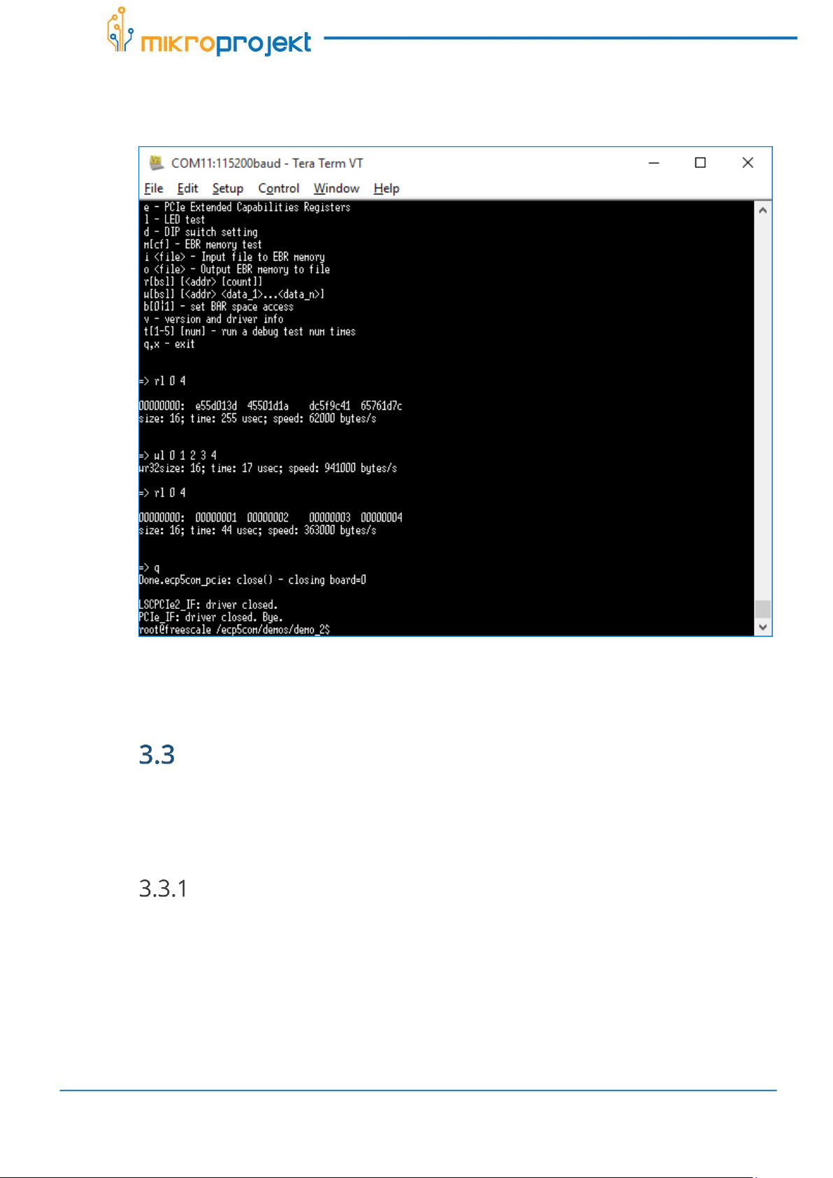
Figure 3: Memory test options
To test the memory, first output current values from some memory locations:
> rl 0 4
(some more or less random values should be shown)
Then write some new values:
> wl 0 1 2 3 4
Verify new values were written:
> rl 0 4
(00000001 00000002 00000003 00000004 should be new contents)
KONDOR AX BASIC Demos Guide
Rev. 1.4
2.10.2015.
10 / 25
Figure 4: Memory reading and writing
Tests other than accessing memory may not work; this is behavior per design.
Demo 3 / RD0013 - loopback test on SFP GigE
over PCIe
For this demo, use files from /ecp5com/demos/demo_3 folder.
Hardware
This demo needs an SGMII network module (Cisco GLC-T) inserted into outer SFP
cage (J9/J10). A network cable is optional since the primary goal of the demo is to
test loopback functionality.

KONDOR AX BASIC Demos Guide
Rev. 1.4
2.10.2015.
11 / 25
Design
FPGA design ecp5com_pcie_sgmii should be used; program it using any method
from Downloading FPGA designs chapter. Both, Slave SPI (.sea and .sed files) and
JTAG (.vme) binaries are already provided in i.MX6 file system. Load Slave SPI
binaries using following:
> cd /epc5com/demos/demo_3
> ../../sspiem.lxe ps_algo.sea ps_data.sed
ARM must be rebooted afterwards. Run:
> reboot
Driver
Compiled driver binary file ecp5pcie.ko is already provided. Load it using:
> insmod ecp5pcie.ko sgmii=1 loopback=1
'sgmii=1' option activates SGMII, instead of RMII, functionality within the driver.
The driver can also automatically detect SGMII or RMII design from design's
reported PCIe subsystem code.
'loopback=1' means driver will not send and receive packets from the connected
network cable (it will activate internal loopback within the PHY).
To activate the driver, run:
> ifconfig eth1 up 192.168.2.222
Optionally, if network connection (must be Gigabit Ethernet) is wanted to test,
loopback should be disabled. If this is done after loading above mentioned driver
with loopback enabled, it must be unloaded first:
> rmmod ecp5pcie.ko
and then loaded again with different loopback value:
> insmod ecp5pcie.ko sgmii=1 loopback=0

KONDOR AX BASIC Demos Guide
Rev. 1.4
2.10.2015.
12 / 25
For activating driver IP address might need to be changed to match address
range used in your LAN. Assuming SFP cage is inserted and a cable connects the
board to a working LAN, you should see a message signaling "Link UP" on serial
terminal.
Test
Compiled test application test_net.lxe is provided. This application verifies only
loopback functionality.
Start it with:
> ./test_net.lxe eth1 normal all
Application should print out that it sent and received some number of test
network packets. Number of sent and received packets must match and packet
contents is checked too.
Figure 5: Loopback test on SFP GigE over PCIe

KONDOR AX BASIC Demos Guide
Rev. 1.4
2.10.2015.
13 / 25
The application supports following options:
argument 1 = interface name to use for executing tests; normally you'd
want to always use 'eth1' here since 'eth0' is already reserved by ARMs
built-in network interface
argument 2 defines test packets destination address:
o'normal' means use test interfaces own MAC address as destination
address of test packets (since we want the packets to return to us)
o'invert' reverses all bytes in destination MAC address - one usage for
this to verify that interface will not receive packets not addressed to
it
o'broadcast' uses 0xFF ... 0xFF broadcast address
argument 3 defines what this instance of the application should do:
o'all' sends and receives test packets
o'send' only sends
o'recv' only receives
Demo 4 / RD0014 - loopback test on RMII PHY
over PCIe
For this demo, use files from /ecp5com/demos/demo_4 folder.
Hardware
This demo does not have any special hardware prerequisites.
Design
FPGA design ecp5com_pcie_rmii should be used; program it using any method
from Downloading FPGA designs chapter. Both, Slave SPI (.sea and .sed files) and
JTAG (.vme) binaries are already provided in i.MX6 file system. Load Slave SPI
binaries using following:
> cd /epc5com/demos/demo_4
> ../../sspiem.lxe pr_algo.sea pr_data.sed
ARM must be rebooted afterwards. Run:

KONDOR AX BASIC Demos Guide
Rev. 1.4
2.10.2015.
14 / 25
> reboot
Driver
Compiled driver binary file ecp5pcie.ko is already provided. Load it using:
> insmod ecp5pcie.ko loopback=1
'sgmii=0' (omitted as it is default parameter value) option activates RMII, instead
of SGMII, functionality within the driver.
'loopback=1' means driver will not send and receive packets from the connected
network cable (it will activate internal loopback within the PHY).
To activate the driver, run:
> ifconfig eth1 up 192.168.2.222
Optionally, if network cable is wanted to test, see example in chapter 3.3.3.
Test
Compiled test application test_net.lxe is provided. It verifies only loopback
functionality.
Start the application using:
> ./test_net.lxe eth1 normal all
Application should print out that it sent and received some number of test
network packets. Number of sent and received packets must match and packet
contents is checked too.

KONDOR AX BASIC Demos Guide
Rev. 1.4
2.10.2015.
15 / 25
Figure 6: Loopback test on RMII PHY over PCIe
Application supported options are provided in previous demo (Demo 3 –chapter
2.3.4).
Demo 5 / RD0015 - loopback test on RMII PHY
over EIM
For this demo, use files from /ecp5com/demos/demo_5 folder.
Hardware
This demo does not have any special hardware prerequisites.
Design
FPGA design ecp5com_eim_rmii should be used; program it using any method
from Downloading FPGA designs chapter. Both, Slave SPI (.sea and .sed files) and

KONDOR AX BASIC Demos Guide
Rev. 1.4
2.10.2015.
16 / 25
JTAG (.vme) binaries are already provided in i.MX6 file system. Load Slave SPI
binaries using following:
> cd /epc5com/demos/demo_5
> ../../sspiem.lxe er_algo.sea er_data.sed
ARM does not need to be rebooted afterwards.
Driver
Compiled driver binary file ecp5eim.ko is already provided. As this demo doesn’t
require reboot, there is a possibility some other driver is already loaded. Check it
with command:
> lsmod
If there is one loaded, unload it first using:
> rmmod <name of file>
(see example of command in chapter 3.3.3).
Driver for this demo should be loaded using:
> insmod ecp5eim.ko loopback=1
'sgmii=0' (omitted as it is default parameter value) option activates RMII, instead
of SGMII, functionality within the driver.
'loopback=1' means driver will not send and receive packets from the connected
network cable (it will activate internal loopback within the PHY).
To activate the driver, run:
> ifconfig eth1 up 192.168.2.222
Optionally, if network cable is wanted to test, see example in chapter 3.3.3.
Test
Compiled test application test_net.lxe is provided. It verifies only loopback
functionality.
Table of contents
Other Mikroprojekt Motherboard manuals


