Miksan Motor EP 150 User manual

CENTRIFUGAL COOLANT PUMPS
USER’S MANUAL

2
MİKSAN MOTOR SANAYİ VE TİCARET A.Ş.
BOSB Bakir ve Pirinc Sanayicileri Sitesi
Menekse Cad. No:1
34524 Beylikduzu-ISTANBUL / TURKEY
Tel : +90 (212) 284 64 00 (Pbx)
Fax: +90 (212) 279 55 67
Santr. GSM : +90 (533) 744 09 09
Web : www.miksanmotor.com
E-mail : [email protected]

3
CONTENTS
FOREWORD .........................................................................................................................................................4
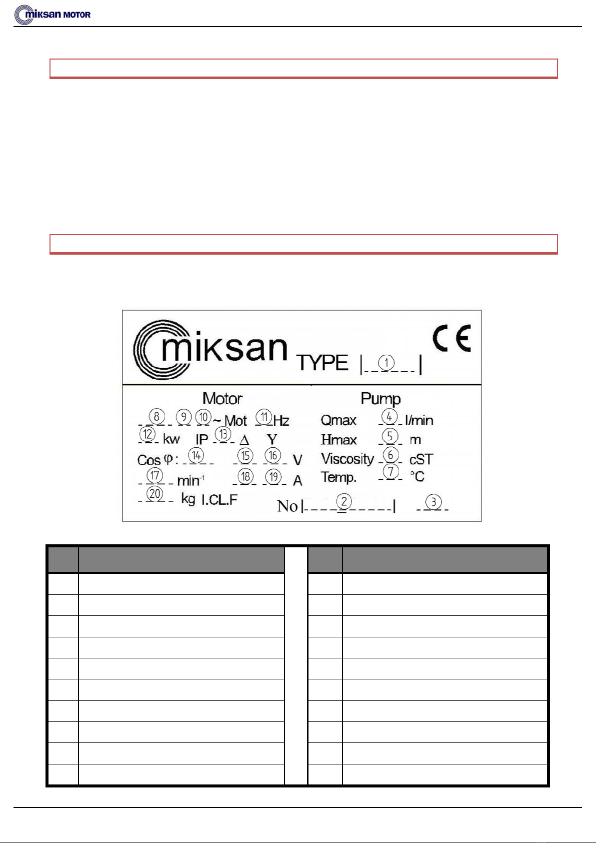
IDENTIFICATION ..................................................................................................................................................4
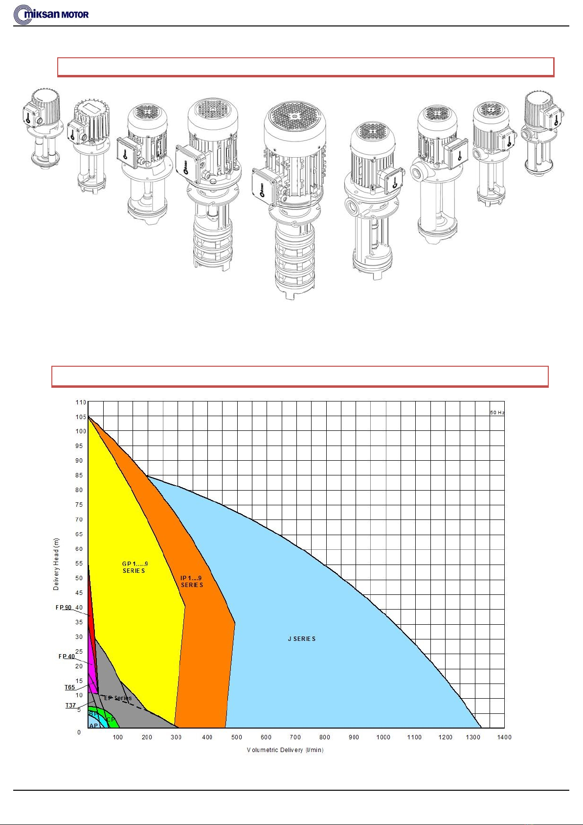
GENERAL .............................................................................................................................................................5
PERFORMANCE RANGE OF PRODUCTS .................................................................................................................5
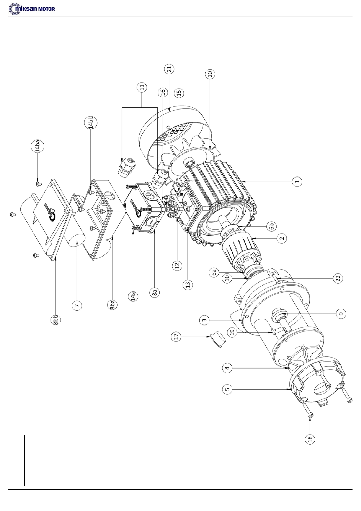
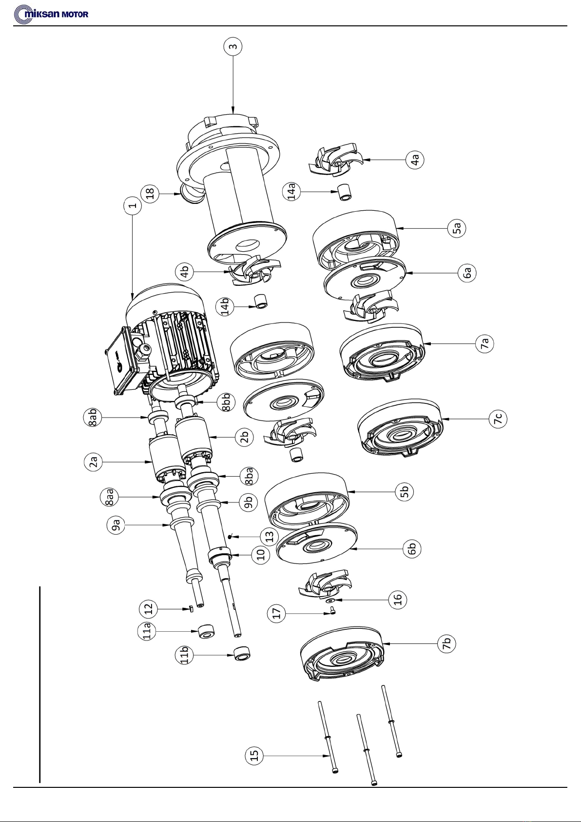
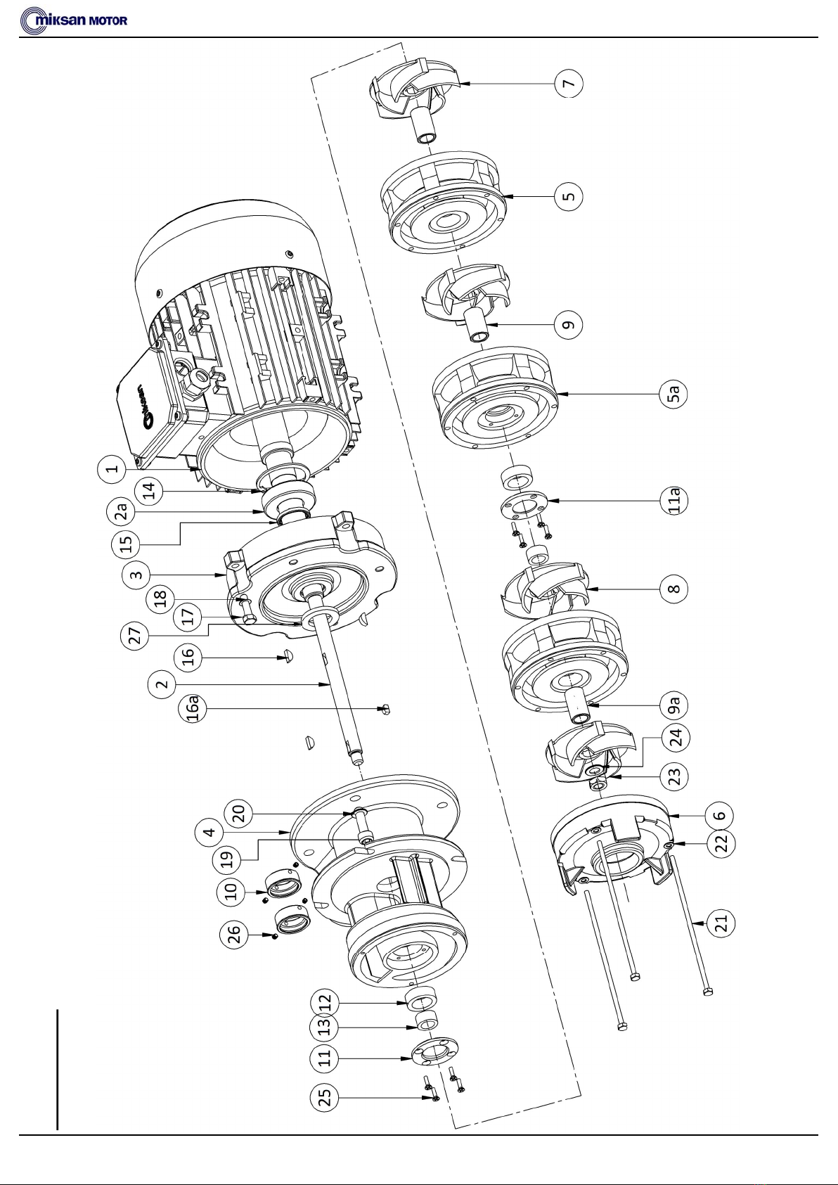
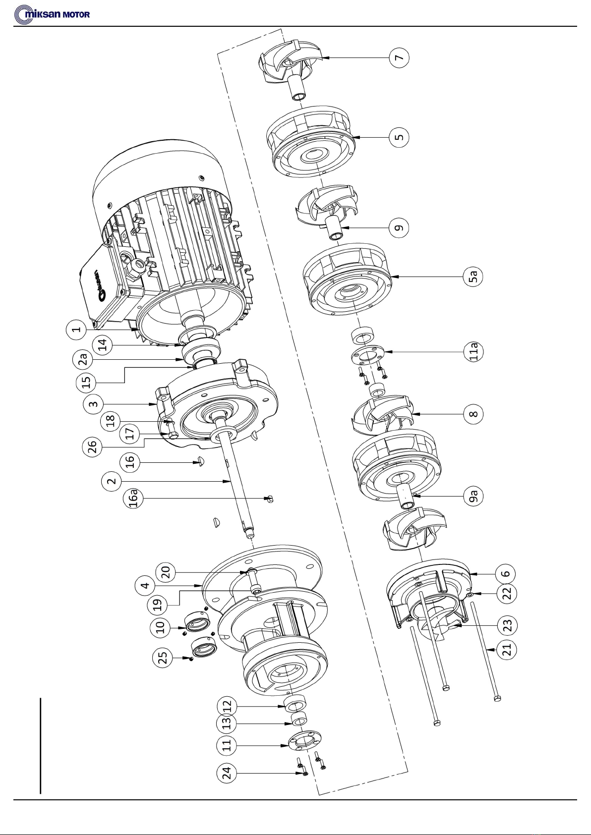
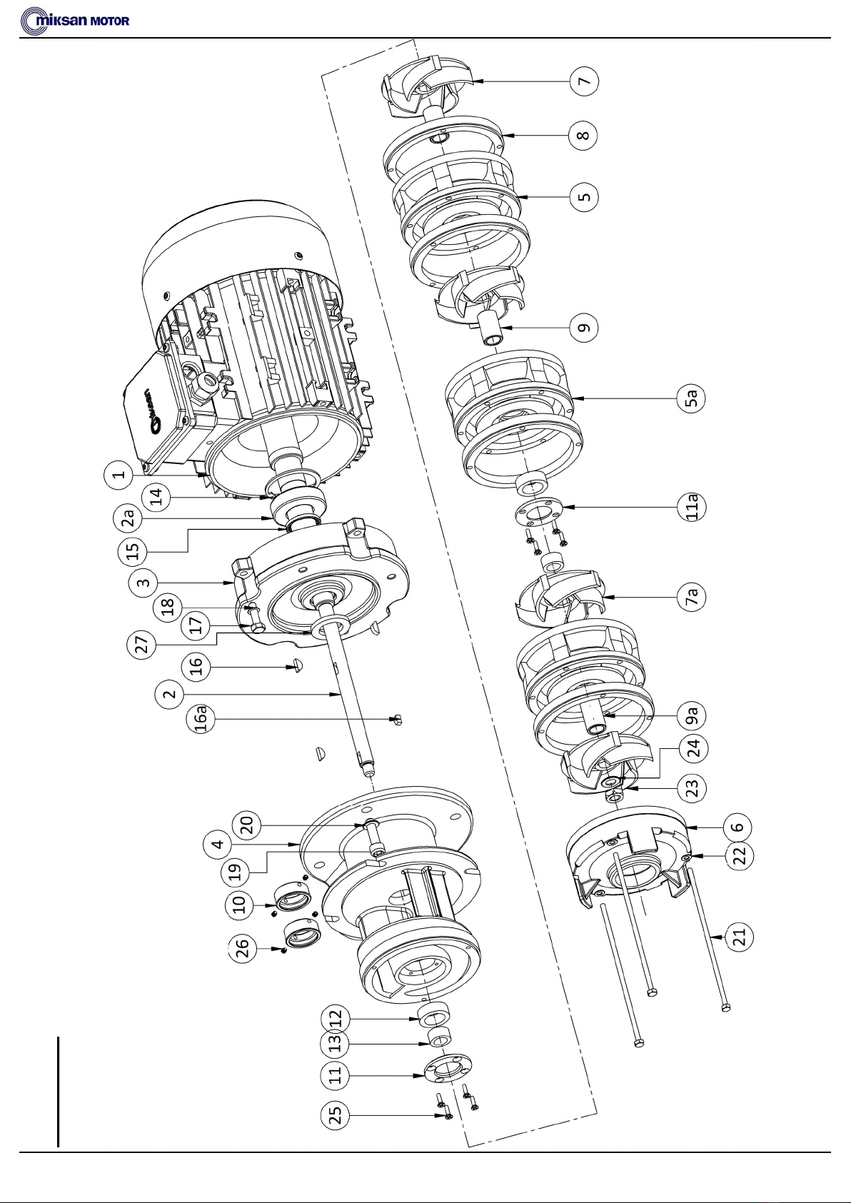
EXPLODED VIEWS ................................................................................................................................................6
AP PUMP ..................................................................................................................................................6
BP PUMP ..................................................................................................................................................8
CP PUMP.................................................................................................................................................10
EP PUMP.................................................................................................................................................12
GP PUMP ................................................................................................................................................14
GPA PUMP ..............................................................................................................................................16
IP PUMP..................................................................................................................................................18
IPA PUMP...............................................................................................................................................20
J SERIES MODULAR PUMP (Single-Stage) ..................................................................................................22
JB SERIES PUMP ......................................................................................................................................24
WARRANTY .......................................................................................................................................................26
SAFETY INSTRUCTIONS ......................................................................................................................................27
TRANSPORT AND STORAGE ...............................................................................................................................29
BEFORE INSTALLATION ......................................................................................................................................29
INSTALLATION ...................................................................................................................................................30
ELECTRICAL CONNECTIONS ................................................................................................................................31
OPERATION .......................................................................................................................................................32
SERVICING AND MAINTENANCE.........................................................................................................................33
TROUBLESHOOTING ................................................................................................................................33
INSTALLATION OF GP, GPA and IP, IPA STAGES WITH BEARING RINGS................................................................34
GENERAL SAFETY NOTES ....................................................................................................................................35

4
FOREWORD
Thank you for choosing Miksan Motor.
This manual contains the installaon, operang and maintenance of the AP, BP, CP, EP, GP/A, IP/A
and J Series type mulstage centrifugal pumps with technical features.
Read the manual carefully before installaon and using the pump. Keep this user’s manual for as long
as the pump is in use.
For detailed informaon, please contact us.
IDENTIFICATION
No Descripon
No Descripon
1Pump Model 11 Frequency (Hz)
2Serial Number 12 Rated Motor Power (kW)
3Producon Date (Month/Year) 13 IP Protecon Class
4Maximum Flow Rate (l/min) 14 Motor Cosφ Value
5Maximum Delivery Head (m) 15 Rated Voltage (V) (Delta Connecon)
6Fluid Viscosity Range (cSt) 16 Rated Voltage (V) (Star Connecon)
7Maximum Operang Temperature (°C) 17 Rated Rotaonal Speed (RPM)
8Motor Frame 18 Rated Current (A) (Delta Connecon)
9Motor Pole Number 19 Rated Current (A) (Star Connecon)
10 Motor Phase 20 Pump Weight (kg)
The nameplate is posioned on the motor and indicates the type model—size, pump performance
data, motor specicaons, serial number and producon date.
Figure 1. Sample Nameplate
Table 1. Descripon of the Values in the nameplate

5
GENERAL
PERFORMANCE RANGE OF PRODUCTS (2-pole at 50Hz)
Figure 2. Centrifugal coolant pumps AP, BP, CP, EP, GP and IP are produced by Miksan Motor.
Figure 3. Performance Characteriscs of Low and Medium Pressure Pumps

6
EXPLODED VIEWS
AP PUMP

7
Item No Descripon Qty
1Pump Motor 1
2Pump sha with rotor (AISI 1040 - DIN C35)* 1
3Pump Body (PP) 1
4Pump Flange 1
5Impeller (PP) 1
6Inlet Cover (PP) 1
7a Front Bearing - 6003 2Z 1
7b Rear Bearing - 6201 2Z 1
8a Three-phase Terminal Box (Polyamide) 1
8ba Single-phase Terminal Box (lower part) (Polyamide) 1
8bb Single-phase Terminal Box (upper part) (Polyamide) 1
9Splash Ring 2
10 Wave Spring Washer 1
11 M16 Connector (DIN 46319) 1
12 Terminal (No. 1) 1
13 Terminal Box Gasket 1
14a Pan Head Screw (for Three-phase Motor) (DIN 7985) 4
14ba Pan Head Screw (for Single-phase Motor-outer terminal) 4
14bb Pan Head Screw (for Single-phase Motor-inner terminal) 4
15 Pan Head Screw (Grounding) 1
16 Pan Head Screw (DIN 7985) 1
17 Socket Head Cap Screw (DIN 912) 2
18 Pipe End Plug 1
19 Pan Head Screw (DIN 7985) 2
20 Capacitor (for Single-phase Motors - 8μF) 1
AP PUMP
* Stainless steel AISI 316 (DIN 4401) (Oponal) , Stainless steel AISI 420
(DIN X20Cr13) (Oponal)

8
BP PUMP

9
Item No Descripon Qty
1Pump Motor 1
2Pump sha with rotor (AISI 1040 - DIN C35) 1
3Pump Body (Al) 1
4Impeller (Al) 1
5Inlet Cover (Al) 1
6a Front Bearing - 6003 2Z 1
6b Rear Bearing - 6201 2Z 1
7Capacitor (for Single-phase Motors- 8μF) 1
8a Three-phase Terminal Box (Polyamide) 1
8ba Single-phase Terminal Box (lower part) (Polyamide) 1
8bb Single-phase Terminal Box (upper part) (Polyamide) 1
9Splash Ring 2
10 Wave Spring Washer 1
11 M16 Connector (DIN 46319) 1
12 Terminal (No. 1) 1
13 Terminal Box Gasket 1
14a Pan Head Screw (for Three-phase Motor) (DIN 7985) 4
14ba Pan Head Screw (for Single-phase Motor-outer terminal) 4
14bb Pan Head Screw (for Single-phase Motor-inner terminal) 4
15 Pan Head Screw (Grounding) (DIN 7985) 1
16 Pan Head Screw (DIN 7985) 1
17 Pipe End Plug 1
18 Pan Head Screw (DIN 7985) 2
BP PUMP

10
CP PUMP

11
Item No Descripon Qty
1Pump Motor 1
2Pump sha with rotor (AISI 1040 - DIN C35)* 1
3Pump Body (Cast iron) 1
4Impeller (Polyamide oponal Brass) 1
5Inlet Cover (Polyamide oponal Cast iron) 1
6a Front Bearing - 6003 2Z 1
6b Rear Bearing - 6202 2Z 1
7Capacitor (for Single-phase Motors - 8μF) 1
8a Three-phase Terminal Box (Polyamide) 1
8ba Single-phase Terminal Box (lower part) (Polyamide) 1
8bb Single-phase Terminal Box (upper part) (Polyamide) 1
9Splash Ring 2
10 Wave Spring Washer 1
11 M16 Connector (DIN 46319) 1
12 Terminal (No. 1) 1
13 Terminal Box Gasket 1
14a Pan Head Screw (for Three-phase Motor) (DIN 7985) 4
14ba Pan Head Screw (for Single-phase Motor-outer terminal) 4
14bb Pan Head Screw (for Single-phase Motor-inner terminal) 4
15 Pan Head Screw (Grounding) (DIN 7985) 1
16 Pan Head Screw (DIN 7985) 1
17 Pipe End Plug 1
18 Socket Head Cap Screw (DIN 912) 3
19 Woodroof key (DIN 6888) 1
20 Fan (Oponal) 1
21 Fan Cover (Oponal) 1
22 Socket Head Cap Screw (DIN 912) 2
CP PUMP
* Stainless steel AISI 420 (DIN X20Cr13) (Oponal)

12
EP 150-250-350 PUMP

13
Item No Descripon Qty
1Pump Motor 1
2a Pump Sha with Rotor * (AISI 1040 - DIN C35) 1
2b Pump Sha with Rotor **(AISI 1040 - DIN C35) 1
3Pump Body (Cast iron) 1
4a Impeller *** (Cast iron) 1-2
4b Impeller ****(Cast iron) 1-3
5a Diuser ***(Cast iron) 1
5b Diuser ****(Cast iron) 1-2
6a Diuser Cover ***(Cast iron) 1
6b Diuser Cover ****(Cast iron) 1-2
7a Inlet Cover *****(Cast iron) 1
7b Inlet Cover ****(Cast iron) 1
7c Inlet Cover ***(Cast iron) 1
8aa Front Bearing *- 6006 2Z 1
8ab Rear Bearing *- 6202 2Z 1
8ba Front Bearing **- 6006 2Z 1
8bb Rear Bearing **- 6202 2Z 1
9a Splash Ring * 2
9b Splash Ring ** 2
10 Splash Ring ** 1
11a Bearing Ring * (C) 1
11b Bearing Ring **(C) 1
12 Woodru Key 1-3
13 Set-screw ** 2
14a Spacer 0-1
14b Spacer 0-2
15 Socket Head Cap Screw (DIN 912) 3
16 Washer **(DIN 125) 0-1
17 Socket Head Cap Screw **(DIN 912) 0-1
18 Pipe End Plug 1
EP 150-250-350 PUMP
* For EP 150-250-350 (single-stage).
** For EP 152-153-252 (mulstage).
*** For EP 250 Series.
**** For EP 150 Series.
*****For EP 350 Series.

14
GP PUMP

15
Item No Descripon Qty
1Pump Motor 1
2Pump Sha with Rotor (AISI 1040 - DIN C35) 1
2a Front Bearing - 6206 2Z 1
2b Rear Bearing - 6204/6205/6206 2Z 1
3Motor Flange 1
4Pump Body (Cast iron) 1
5Diuser (Cast iron) 1-8
5a Diuser with bearing rings (Cast iron)* 0-1
6Inlet Cover (Cast iron) 1
7Impeller (Brass) 1-9
8Impeller with Bearing Ring (Brass)* 0-1
9Spacer Sleeve 0-8
10 Splash Ring 2
11 Thrust Flange 1
11a Thrust Flange* 0-1
12 Outer Bearing Ring (SiC) (See also: Page 30) 1-2
13 Inner Bearing Ring (SiC) (See also: Page 30) 1-2
14 Bearing Circlip (DIN 472) 1
15 Oil Seal** 2
16 Woodru Key (DIN 6888) 1-8
16a Half Woodru Key (DIN 6888) 0-1
17 Socket Head Cap Screw (DIN 912) 4
18 Split Lock Washer (DIN 127) 4
19 Socket Head Cap Screw (DIN 912) 4
20 Split Lock Washer (DIN 127) 4
21 Tie Bolt 4
22 Split Lock Washer (DIN 127) 4
23 Self-Locking Nut (DIN 982) 1
24 Washer (DIN 125) 1
25 Flat Head Screw (DIN 965) 4
26 Set-screw (DIN 916) 4
27 Splash Ring 1
GP PUMP
* For GP 5-6-7-9 series pump.
** For 100 - 112 and 132 motor frame.

16
GPA PUMP

17
Item No Descripon Qty
1Pump Motor 1
2Pump Sha with Rotor (AISI 1040 - DIN C35) 1
2a Front Bearing - 6206 2Z 1
2b Rear Bearing - 6204/6205/6206 2Z 1
3Motor Flange 1
4Pump Body (Cast iron) 1
5Diuser (Cast iron) 1-8
5a Diuser with bearing rings (Cast iron)* 0-1
6Inlet Cover (Cast iron) 1
7Impeller (Brass) 1-9
8Impeller with Bearing Ring (Brass)* 0-1
9Spacer Sleeve 0-8
10 Splash Ring 2
11 Thrust Flange 1
11a Thrust Flange* 0-1
12 Outer Bearing Ring (SiC) (See also: Page 30) 1-2
13 Inner Bearing Ring (SiC) (See also: Page 30) 1-2
14 Bearing Circlip (DIN 472) 1
15 Oil Seal** 2
16 Woodru Key (DIN 6888) 1-8
16a Half Woodru Key (DIN 6888) 0-1
17 Socket Head Cap Screw (DIN 912) 4
18 Split Lock Washer (DIN 127) 4
19 Socket Head Cap Screw (DIN 912) 4
20 Split Lock Washer (DIN 127) 4
21 Tie Bolt 4
22 Split Lock Washer (DIN 127) 4
23 Axial Impeller 1
24 Flat Head Screw (DIN 965) 4
25 Set-screw (DIN 916) 4
26 Splash Ring 1
GPA PUMP
* For GPA 3-4-5-6-7 series pump.
** For 100 - 112 and 132 motor frame.

18
IP PUMP

19
Item No Descripon Qty
1Pump Motor 1
2Pump Sha with Rotor (AISI 1040 - DIN C35) 1
2a Front Bearing - 6206 2Z 1
2b Rear Bearing - 6204/6205/6206 2Z 1
3Motor Flange 1
4Pump Body (Cast iron) 1
5Diuser (Cast iron) 1-8
5a Diuser with bearing rings (Cast iron)* 0-1
6Inlet Cover (Cast iron) 1
7Impeller (Cast iron) 1-9
7a Impeller with Bearing Ring (Cast iron)* 0-1
8Diuser Plate (Cast iron) 1-9
9Spacer Sleeve 0-8
10 Splash Ring 2
11 Thrust Flange 1
11a Thrust Flange* 0-1
12 Outer Bearing Ring (SiC) (See also: Page 30) 1-2
13 Inner Bearing Ring (SiC) (See also: Page 30) 1-2
14 Bearing Circlip (DIN 472) 1
15 Oil Seal** 2
16 Woodru Key (DIN 6888) 1-8
16a Half Woodru Key (DIN 6888) 0-1
17 Socket Head Cap Screw (DIN 912) 4
18 Split Lock Washer (DIN 127) 4
19 Socket Head Cap Screw (DIN 912) 4
20 Split Lock Washer (DIN 127) 4
21 Tie Bolt 4
22 Split Lock Washer (DIN 127) 4
23 Self-Locking Nut (DIN 982) 1
24 Washer (DIN 125) 1
25 Flat Head Screw (DIN 965) 4
26 Set-screw (DIN 916) 4
27 Splash Ring 1
IP PUMP
* For IP 4-5-7-9 series pump.
** For 100 - 112 and 132 motor frame.

20
IPA PUMP
This manual suits for next models
2
Table of contents
Other Miksan Motor Water Pump manuals
Popular Water Pump manuals by other brands

Franklin Electric
Franklin Electric LittleGIANT VCMX Series owner's manual

Aesus
Aesus AESFill AF1 owner's manual

Barnes
Barnes 3SE3054DS Installation and operation manual

SPORTSTECH
SPORTSTECH TM400 manual

Cartrend
Cartrend 10942 Original operating instructions

Nittoh
Nittoh UP-45SV Series Operation and maintenance manual